
ESP32 S3 - 74HC595 4-Digit 7-Segment Display
Learn how to connect a 74HC595 4-digit 7-segment display to your ESP32 S3 and display numbers, text, and sensor readings using just three GPIO pins. This beginner-friendly tutorial covers everything from wiring and library setup to creating digital clocks, temperature displays, and counters.
What you'll build:
- A working 4-digit 7-segment display driven by the 74HC595 shift register on the ESP32 S3
- Integer and floating-point number displays with optional zero-padding
- A text and temperature display using degree symbols and custom characters
- A digital clock display in HH.MM format with a blinking colon separator
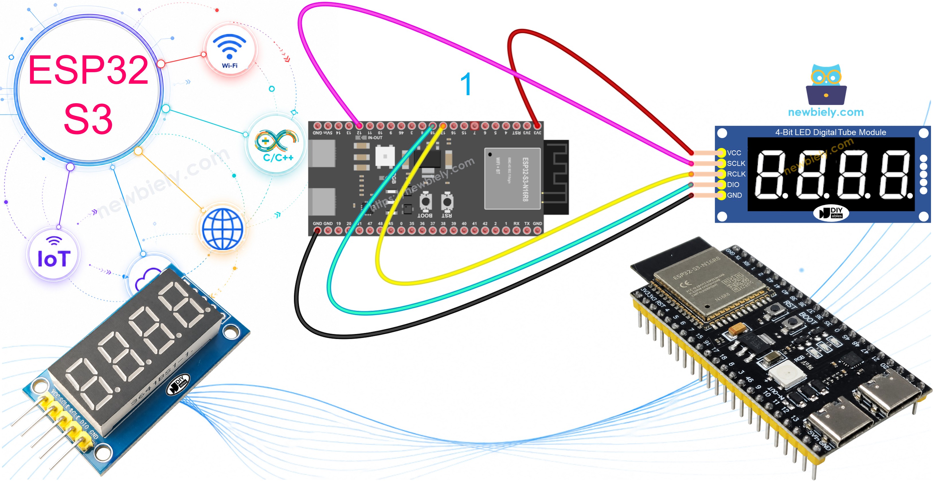
Hardware Preparation
Or you can buy the following kits:
| 1 | × | DIYables ESP32 S3 Starter Kit (ESP32 S3 included) | |
| 1 | × | DIYables Sensor Kit (18 sensors/displays) |
Additionally, some of these links are for products from our own brand, DIYables .
Overview of the 74HC595 4-Digit 7-Segment Display
The 74HC595 4-digit 7-segment display is a serial-to-parallel shift register module that controls four LED digit displays using only three control pins instead of twelve. It is compatible with 3.3V logic levels, making it an ideal companion for the ESP32 S3. The module handles common anode configurations and supports digits 0–9, letters A–F, and a selection of text characters, along with built-in decimal points between digits.
Key Specifications
The module operates at 3.3V to 5V, making it fully compatible with the ESP32 S3's 3.3V output without any level shifting. It uses the 74HC595 shift register IC to accept serial data and latch it to the LED outputs via the register clock. Multiplexing across all four digits is handled automatically by the DIYables library — you call print() and the display updates instantly. Each digit contains seven LED segments plus one decimal point, giving you the building blocks for numbers, letters, and symbols.
The module exposes five essential pins. SCLK (SH_CP) is the serial clock pin that pulses data bits into the shift register one at a time. RCLK (ST_CP) is the register clock pin that latches the shifted data to the LED outputs. DIO (DS) is the data input pin that receives the serial data stream. VCC connects to your 3.3V supply, and GND connects to common ground.
Wiring Diagram
Connect the 74HC595 display module to your ESP32 S3 using the five-pin interface described below.
The ESP32 S3 operates at 3.3V logic levels, and the 74HC595 module works perfectly at this voltage, so no level shifting is required. Double-check VCC and GND polarity before powering on to avoid damaging the module.
Safety Notes
Do not connect VCC to 5V unless your specific module includes built-in level shifters, as exceeding 3.3V on the data lines can damage the ESP32 S3's GPIO pins. Ensure all jumper wire connections are secure — loose connections cause flickering or blank digits and can be difficult to diagnose. Always verify that the GND of the display module is connected to the GND of the ESP32 S3 to form a common ground.
| Display Pin | ESP32 S3 Pin |
|---|---|
| SCLK (SH_CP) | GPIO12 |
| RCLK (ST_CP) | GPIO17 |
| DIO (DS) | GPIO18 |
| VCC | 3.3V |
| GND | GND |
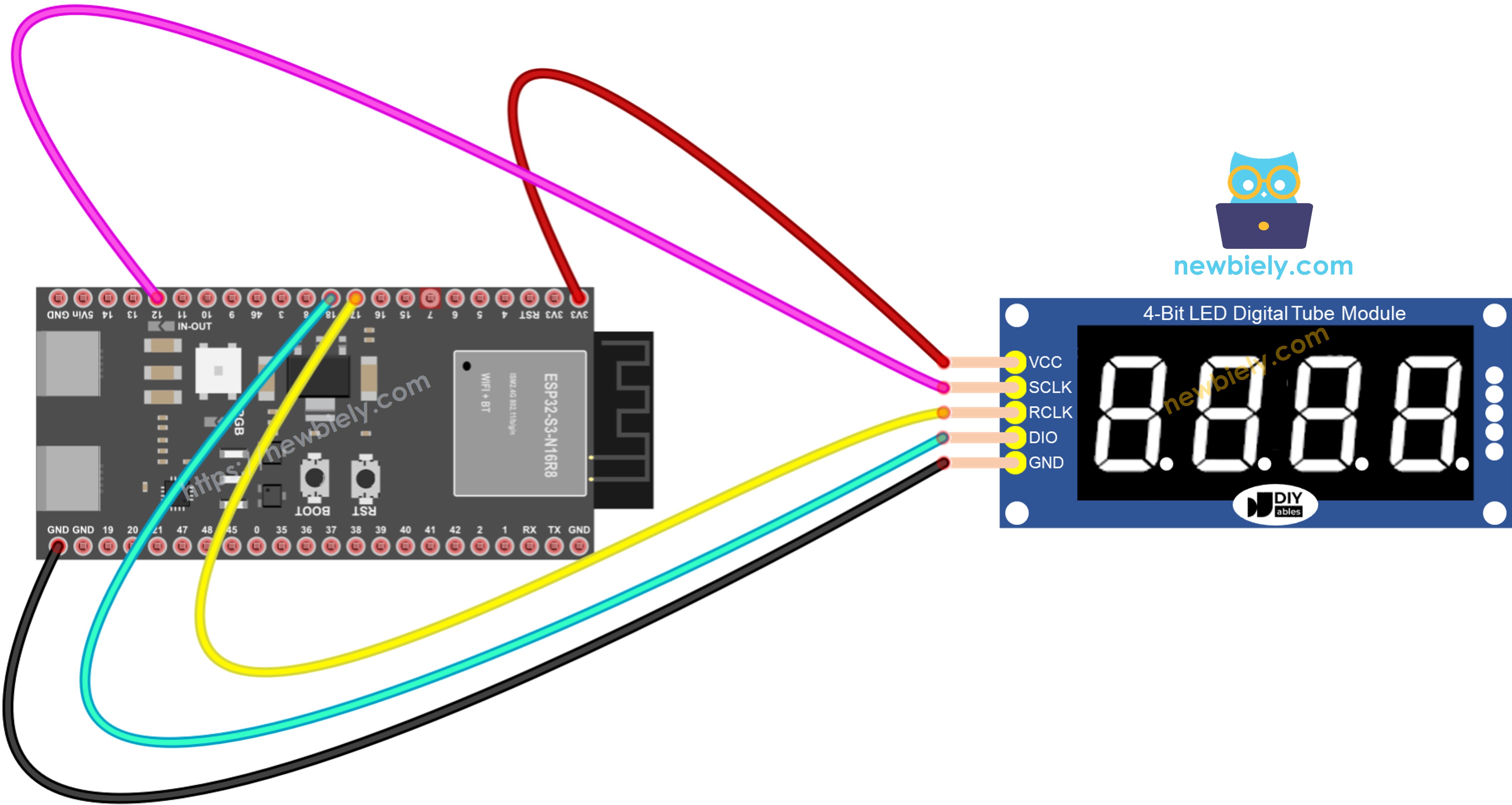
This image is created using Fritzing. Click to enlarge image
Library Setup
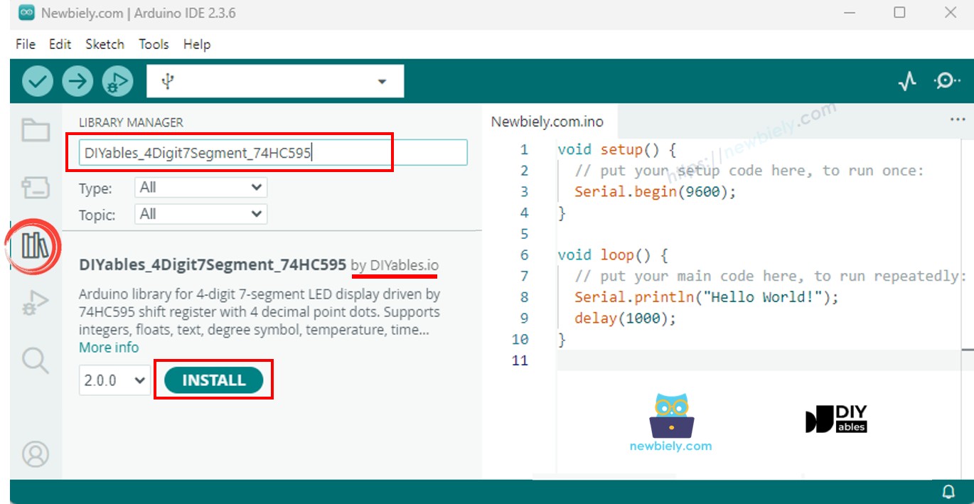
The DIYables_4Digit7Segment_74HC595 library abstracts all shift register timing and display multiplexing so you can focus on what to show rather than how to drive the hardware. Install it through the Arduino IDE Library Manager before uploading any of the tutorial sketches.
The following steps walk you through installation:
- New to ESP32 S3? Complete our Getting Started with ESP32 S3 guide first to set up your development environment.
- Connect your ESP32 S3 to your computer using the USB-C cable.
- Open the Arduino IDE software on your computer.
- Select ESP32 S3 from the board list.
- Choose the correct COM port for your ESP32 S3.
- Click the Libraries icon on the left sidebar to open Library Manager.
- Type "DIYables_4Digit7Segment_74HC595" in the search field.
- Find the DIYables entry and click Install.
- Select version 2.0.0 or later for best compatibility.
Starter Sketch
The following code is the minimum required to get your 74HC595 4-digit display working with the ESP32 S3. It initializes the display and shows the number 1234 as soon as the board boots. The display.loop() call in the main loop keeps the multiplexing running so the digits remain lit continuously.
display.begin() configures the three GPIO pins as outputs and prepares the shift register for communication. Because the display uses multiplexing to illuminate one digit at a time in rapid succession, display.loop() must be called as often as possible — use display.delay() instead of the standard delay() anywhere you need a pause so the display stays refreshed during the wait.
Tutorial - Display Integers
This tutorial shows how to display integer values on the ESP32 S3 74HC595 4-digit 7-segment display, including negative numbers and zero-padded output.
Detailed Instructions
- New to ESP32 S3? Complete our Getting Started with ESP32 S3 guide first.
- Wire the 74HC595 module to your ESP32 S3 following the wiring diagram above.
- Connect the ESP32 S3 to your computer via USB-C cable.
- Open the Arduino IDE and select the ESP32 S3 board and correct COM port.
- Copy the integer display code and paste it into Arduino IDE.
- Click the Upload button to transfer the code to your board.
- Open the Serial Monitor to view output messages.
- Watch the 7-segment display cycle through different integers.
- Pro Tip: The second parameter in print(42, true) enables zero-padding for consistent-width displays.
Serial Monitor Output
The display cycles through various integers including zero, positive numbers, negative numbers, and zero-padded format.
Method Reference
| Method | Action | Syntax |
|---|---|---|
| print(int) | Display an integer value | display.print(1234) |
| print(int, true) | Display integer with zero-padding | display.print(42, true) |
| loop() | Refresh display multiplexing | display.loop() |
| begin() | Initialize display pins | display.begin() |
Tutorial - Display Floats
This tutorial demonstrates displaying floating-point numbers on your ESP32 S3 with automatic and fixed decimal places.
Detailed Instructions
- New to ESP32 S3? Complete our Getting Started with ESP32 S3 guide first.
- Copy the float display code and upload it to your ESP32 S3.
- Open the Serial Monitor to view what is being displayed.
- Watch the display cycle through floats with different decimal place settings.
- Note how auto-decimal adjusts automatically versus a fixed decimal count.
- Pro Tip: Use fixed decimal places for consistent sensor readings such as temperature or voltage.
Serial Monitor Output
Tutorial - Text and Temperature
This tutorial shows how to display text strings, temperature readings with degree symbols, and custom characters on the ESP32 S3 7-segment display.
Detailed Instructions
- New to ESP32 S3? Complete our Getting Started with ESP32 S3 guide first.
- Transfer the text and temperature code to your ESP32 S3.
- Open the Serial Monitor to track what text and symbols are being displayed.
- Observe how letters appear on the 7-segment display.
- Note the small degree circle used for temperature displays.
- Pro Tip: Not all letters display clearly on 7-segment — stick to numbers and characters such as H, E, L, P, C, and O for the best results.
Serial Monitor Output
Tutorial - Time
This tutorial demonstrates creating a digital clock display on your ESP32 S3 with HH.MM format and a blinking colon separator.
Detailed Instructions
- New to ESP32 S3? Complete our Getting Started with ESP32 S3 guide first.
- Transfer the time display code to your ESP32 S3.
- Open the Serial Monitor to view timestamp updates.
- Watch the display show time in HH.MM format with a blinking separator.
- Pro Tip: Combine this with an RTC module for a fully working clock project.
Serial Monitor Output
Tutorial - Blink
This tutorial shows how to blink the entire display content on and off for attention-getting effects on your ESP32 S3.
Detailed Instructions
- New to ESP32 S3? Complete our Getting Started with ESP32 S3 guide first.
- Transfer the blink demo code to your ESP32 S3.
- Open the Serial Monitor to track blink cycles and content changes.
- Observe numbers, decimals, and text blinking on and off.
- Note that each content type blinks five times before switching.
- Pro Tip: Use blinking to draw attention to alarm conditions or important notifications in your projects.
Serial Monitor Output
Troubleshoot
Common issues when using the 74HC595 4-digit 7-segment display with ESP32 S3 and their solutions:
| Issue | Possible Cause | Resolution |
|---|---|---|
| Display blank | Wiring problem | Check VCC, GND, and all three data pin connections |
| Display blank | Power issue | Verify 3.3V is present at VCC pin with multimeter |
| Wrong characters | Anode/cathode mismatch | Pass false as 4th parameter to constructor for common cathode modules |
| Flickering display | delay() blocking loop() | Replace all delay() calls with display.delay() to maintain multiplexing |
| Random segments | Loose wiring | Secure jumper wire connections and check for shorts |
| Dim display | Low voltage | Ensure stable 3.3V power supply to VCC pin |
| Upload fails | Board in wrong mode | Hold BOOT button while pressing RESET, then retry upload |
| No Serial output | Wrong baud rate | Set Serial Monitor to 115200 baud to match code |
| Code won't compile | Library not installed | Install DIYables_4Digit7Segment_74HC595 library version 2.0.0+ |
| Port not found | Driver issue | Install the appropriate USB driver for ESP32 S3 |
Applications and Project Ideas
The ESP32 S3 paired with a 74HC595 4-digit display opens up a wide range of practical and fun projects, from simple counters to WiFi-connected instruments.
- Digital thermometer: Display room temperature from a DHT11 or DS18B20 sensor with a degree symbol.
- Countdown timer: Create a kitchen timer or event countdown with hours and minutes.
- Score keeper: Build a simple scoreboard for games or competitions.
- Stopwatch: Make a digital stopwatch with split-time capability.
- Voltage meter: Monitor battery voltage or power supply levels in real-time.
- Visitor counter: Count people entering through a door using an IR sensor.
- RPM display: Show motor speed for robotics or RC projects.
- Clock with WiFi sync: Build an NTP-synchronized clock using the ESP32 S3's built-in WiFi.
- Lap timer: Track lap times for slot car racing or running.
- Temperature alarm: Display temperature and blink when a threshold is exceeded.
Video Tutorial
Watch the step-by-step video walkthrough for this ESP32 S3 project below.
Challenge Yourself
Once you have the basics working, these progressive challenges will help you deepen your understanding of the 74HC595 display and the ESP32 S3's capabilities.
- Beginner: Modify the integer tutorial to count from 0 to 9999 continuously at one-second intervals.
- Beginner: Display your age or birth year on the screen with zero-padding enabled.
- Intermediate: Create a two-button counter with one button to increment and one to decrement the displayed value.
- Intermediate: Build a temperature display that alternates between Celsius and Fahrenheit every three seconds.
- Advanced: Make a WiFi-connected clock that gets the current time from an NTP server and displays it in HH.MM format with a blinking colon.
- Advanced: Create a countdown timer that accepts input from the Serial Monitor and sounds a buzzer when it reaches zero.