
ESP32 S3 - RS422
RS422 is a robust serial communication standard capable of transmitting data over long distances and in electrically noisy environments, making it ideal for industrial applications. This tutorial shows you how to connect a TTL to RS422 module to the ESP32 S3 and exchange data bidirectionally between the board and your PC.
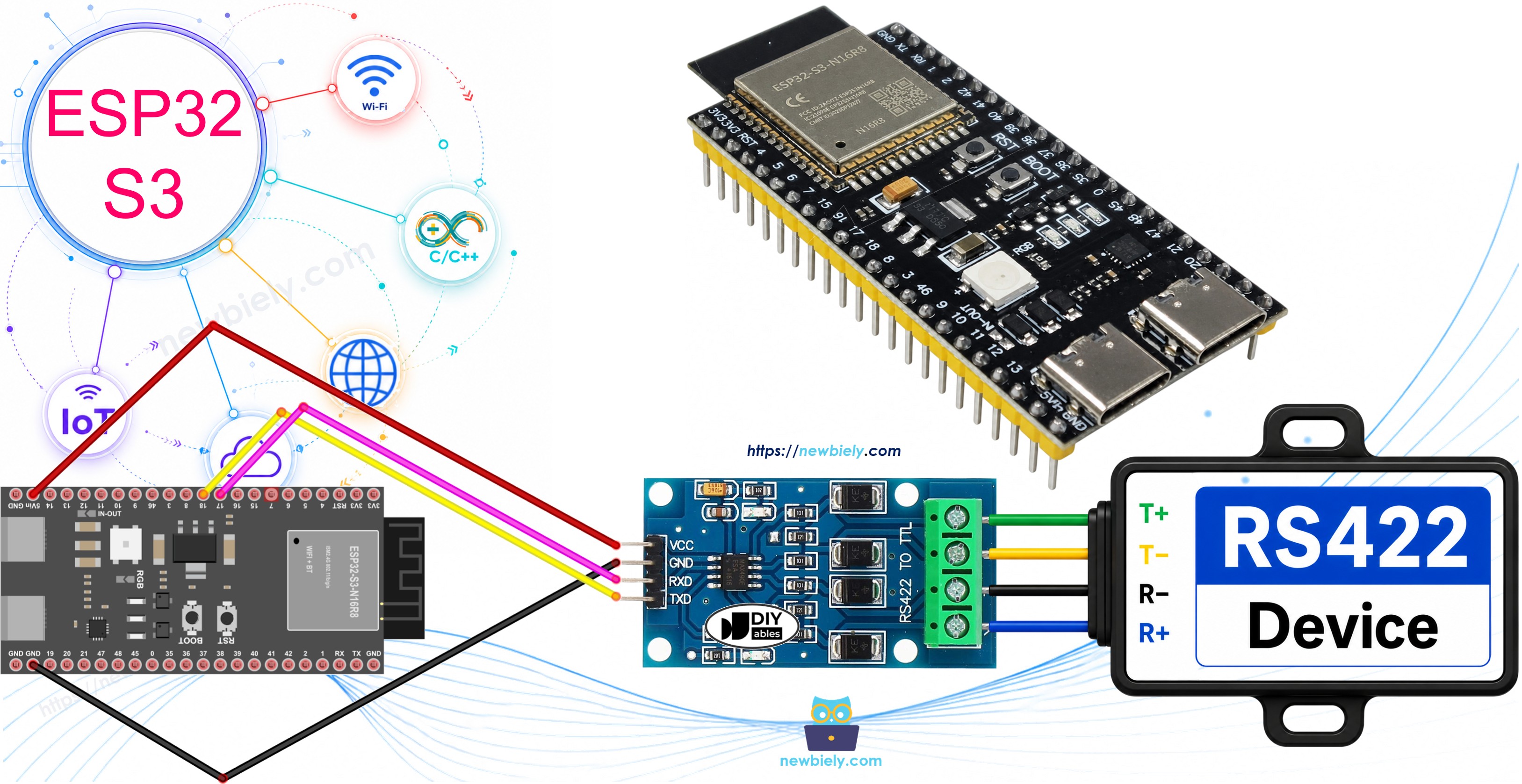
What you'll build:
- Connect the ESP32 S3 to a TTL to RS422 module
- Program the ESP32 S3 to receive data from the RS422 interface
- Program the ESP32 S3 to send data through the RS422 interface
- Establish bidirectional serial communication between your PC and ESP32 S3 over RS422
Hardware Preparation
Or you can buy the following kits:
| 1 | × | DIYables ESP32 S3 Starter Kit (ESP32 S3 included) | |
| 1 | × | DIYables Sensor Kit (18 sensors/displays) |
Additionally, some of these links are for products from our own brand, DIYables .
Overview of TTL to RS422 Module
RS422 (also referred to as RS-422) is a differential serial communication standard that supports full-duplex data transmission at speeds up to 10 Mbps over distances of up to 1200 meters. Unlike TTL-level signals used natively on the ESP32 S3, RS422 uses balanced differential pairs, which offer excellent noise immunity and the ability to drive long cable runs.
When using serial communication on the ESP32 S3 via functions such as Serial.print(), Serial.read(), and Serial.write(), data is transmitted at TTL signal levels through the TX and RX pins. A TTL to RS422 converter module bridges the gap between these TTL signals and the differential RS422 standard, enabling long-distance and noise-resistant serial communication.
Key Specifications
- Communication standard: RS-422 (full-duplex, differential signaling)
- Supply voltage: 3.3V or 5V (check your module's datasheet)
- Maximum data rate: up to 10 Mbps
- Maximum cable length: up to 1200 m at lower baud rates
- Common driver ICs: MAX13487, MAX3422 or equivalents
Pinout
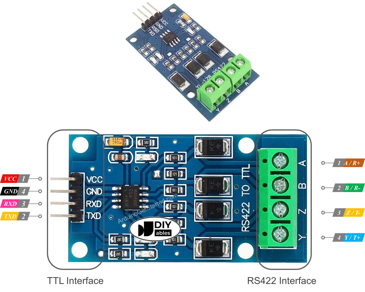
The TTL to RS422 module features two interfaces. Connect the TTL side to the ESP32 S3 and the RS422 side to the remote device or cable.
TTL Interface (connected to ESP32 S3):
- VCC Pin: Power input — connect to 3.3V or 5V.
- GND Pin: Ground — connect to GND.
- RXD Pin: Data input to module — connect to a TX pin of the ESP32 S3.
- TXD Pin: Data output from module — connect to an RX pin of the ESP32 S3.
RS422 Interface:
- A (R+) Pin: RX+ of the module — connect to the TX+ (T+ or Y) pin of the remote RS422 device.
- B (R-) Pin: RX- of the module — connect to the TX- (T- or Z) pin of the remote RS422 device.
- Y (T+) Pin: TX+ of the module — connect to the RX+ (R+ or A) pin of the remote RS422 device.
- Z (T-) Pin: TX- of the module — connect to the RX- (R- or B) pin of the remote RS422 device.
Wiring Diagram
Connect the TTL to RS422 module to the ESP32 S3 as shown in the diagram below, ensuring the TX/RX lines are crossed correctly between the board and the module. The RS422 interface side can then be connected to a PC via an RS422-to-USB cable or to another RS422 device.
Safety Notes
Use shielded twisted-pair cable for the RS422 differential lines (A/B and Y/Z pairs) whenever running cable over distances greater than a few meters, as this significantly reduces noise susceptibility. Always ensure that all devices in the RS422 network share a common ground reference to avoid ground loops and potential damage to the transceivers.
| ESP32 S3 Pin | RS422 Module TTL Pin |
|:---|:---|
| 3.3V | VCC |
| GND | GND |
| TX (any UART TX) | RXD |
| RX (any UART RX) | TXD |
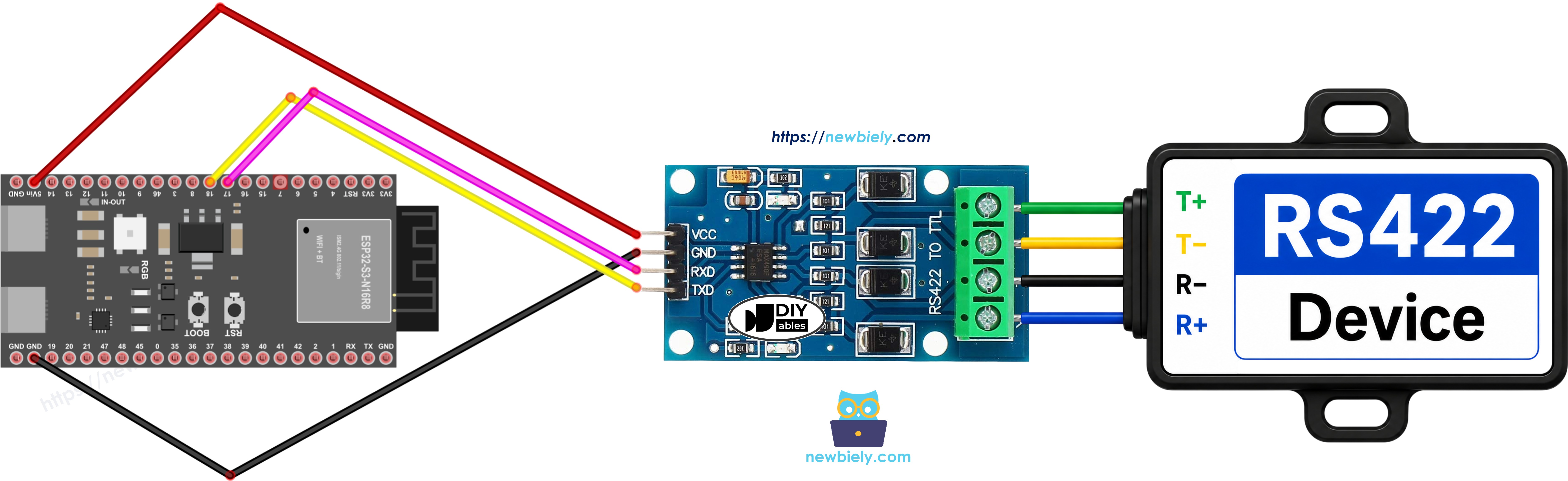
This image is created using Fritzing. Click to enlarge image
How To Program ESP32 S3 to Use the RS422 Module
Programming the ESP32 S3 to communicate over RS422 is straightforward because the conversion between TTL and RS422 is handled entirely by the module. The following code uses the hardware serial interface Serial2 to send and receive data through the module, and mirrors incoming data back to the USB serial monitor for verification.
To initialize the serial interface for RS422, call begin() on the desired hardware UART:
To read data arriving from the RS422 interface, use any of these Serial functions:
To write data to the RS422 interface, use any of these Serial functions:
For a complete list of available functions, see the Serial reference.
ESP32 S3 Code
Detailed Instructions
Follow these steps to get the ESP32 S3 communicating over RS422:
- New to ESP32 S3? Complete our Getting Started with ESP32 S3 guide first.
- Wire the TTL to RS422 module to the ESP32 S3 according to the wiring diagram above.
- Connect the ESP32 S3 to your PC using a USB Type-C cable.
- Open the Arduino IDE and paste the code provided in the Code section.
- Select the correct board and COM port under Tools.
- Click Upload to flash the code to the ESP32 S3.
- Connect the RS422 side of the module to a PC using an RS422-to-USB cable.
- Open two Serial Terminal windows (e.g., Tera Term or PuTTY): one on the ESP32 S3 COM port and one on the RS422 adapter COM port, both set to 9600 baud.
- Type text in either terminal and verify it appears in the other terminal.
- Pro Tip: Use a logic analyzer or oscilloscope on the RS422 differential pair lines to confirm the differential signaling and measure actual signal integrity over your cable.
Serial Monitor Output
After uploading and establishing the RS422 connection, the Serial Monitor will display incoming and echoed data similar to the following readings:
Applications
RS422 with the ESP32 S3 is well suited for scenarios that demand reliable long-distance or noise-resistant serial communication. Here are common real-world uses:
- Industrial Automation: Connect the ESP32 S3 to PLCs, sensors, or HMI panels in factory environments where cable runs can exceed 100 m.
- Point-of-Sale Systems: Integrate with receipt printers, barcode scanners, or card readers that use RS422 interfaces.
- Building Automation: Interface with HVAC controllers, access control panels, or lighting systems using RS422 backbones.
- Data Acquisition: Collect sensor readings from remote field instruments and relay them to a central controller or PC.
- Legacy Equipment Integration: Bridge modern ESP32 S3-based IoT systems with older industrial equipment that exposes only RS422 serial ports.
Video Tutorial
Watch the step-by-step video walkthrough for this ESP32 S3 project below.
Challenges
Now that you have RS422 communication working on the ESP32 S3, try these challenges to deepen your understanding.
- Beginner: Modify the code so the ESP32 S3 sends a status message (e.g., "ESP32 S3 Online") over RS422 once per second, and verify receipt on the terminal.
- Intermediate: Implement a simple command protocol where the PC sends text commands (e.g., "LED_ON", "LED_OFF") over RS422 and the ESP32 S3 toggles an LED and replies with a confirmation message.
- Advanced: Build a multi-drop RS422 network using multiple TTL to RS422 modules and ESP32 S3 boards, implementing an address-based message routing scheme so each node only processes messages addressed to it.