
ESP32 S3 - Button
Learning to use a button with your ESP32 S3 is one of the most foundational skills in embedded development. This tutorial walks you through everything you need — wiring, code, and common pitfalls — so you can confidently add button input to any ESP32 S3 project.
What you'll build:
- A circuit connecting a push button to the ESP32 S3 using the internal pull-up resistor
- A sketch that reads and prints the button state to the Serial Monitor
- An enhanced version that detects press and release events separately
- A foundation for real-world applications like counters, toggles, and security triggers
※ NOTE THAT:
Before presenting about the button, We would like to notice that there are two common mistakes that newbies usually meet:
- The floating input problem:
- Symptom: When connecting a button to ESP32 S3 input pin, the state of the input pin is random and not matched with the button's pressing state.
- Cause: The button pin is NOT used a pull-down resistor or a pull-up resistor.
- Solution: ⇒ Use a pull-down resistor or a pull-up resistor on the input pin. The detail will be described later in this tutorial.
- Symptom: The code on ESP32 S3 reads the state of the button and identifies the pressing event by detecting the state change (HIGH to LOW, or LOW to HIGH). When the button is actually pressed only one time, ESP32 S3 code detects multiple presses rather than once.
- Cause: Due to mechanical and physical characteristics, when you do a single press on a button, the state of the input pin is quickly toggled between LOW and HIGH several times rather than once
- Solution: ⇒ Debounce. The detail will be described in ESP32 S3 - Button - Debounce tutorial.
The chattering phenomenon causes the malfunction in only some kinds of application that needs to detect exactly number of the pressing. In some kind of application, it is harmless.
Hardware Preparation
Or you can buy the following kits:
| 1 | × | DIYables ESP32 S3 Starter Kit (ESP32 S3 included) | |
| 1 | × | DIYables Sensor Kit (18 sensors/displays) |
Additionally, some of these links are for products from our own brand, DIYables .
Overview of Button
A push button is a simple electromechanical switch that closes an electrical circuit when pressed and opens it when released. Despite its simplicity, the button is one of the most versatile input devices you will use in ESP32 S3 projects, enabling user interaction with minimal hardware.
Key Specifications
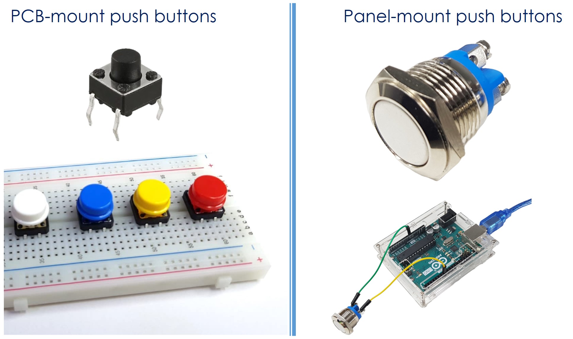
PCB-mount push buttons are designed for breadboard prototyping and solder-in applications. Panel-mount push buttons fit into enclosures for finished projects. Button modules include a built-in pull-down resistor, which simplifies wiring and ensures a stable signal without any external components.
Button Pinout
PCB-Mount Button (4 pins)
A PCB-mount button has four pins that are internally connected in pairs, giving the component mechanical stability when you press it down on a breadboard.
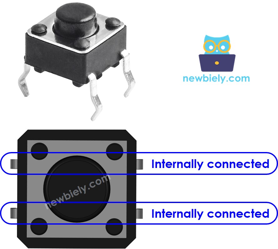
The four pins reduce to two electrically distinct terminals. When selecting which pins to wire, choose one pin from each pair:
- Four pins are arranged in two internally-connected pairs
- Only two of the four pins need to be connected in your circuit
- Any combination that picks one pin from each pair will work correctly
- The extra pins add physical stability to resist pressing force

Panel-Mount Button (2 pins)
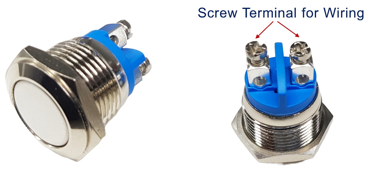
A panel-mount button has two straightforward pins with no internal pairing — simply connect one pin to your GPIO and the other to GND (or VCC, depending on your wiring method).
Button Module (3 pins)
The button module integrates a pull-down resistor on the board itself, making it the most beginner-friendly option. Its three pins are:
- GND: Connect to ground
- VCC: Connect to 3.3V power supply
- OUT: Connect to ESP32 S3 digital input pin (outputs LOW when not pressed, HIGH when pressed)
How Button Works
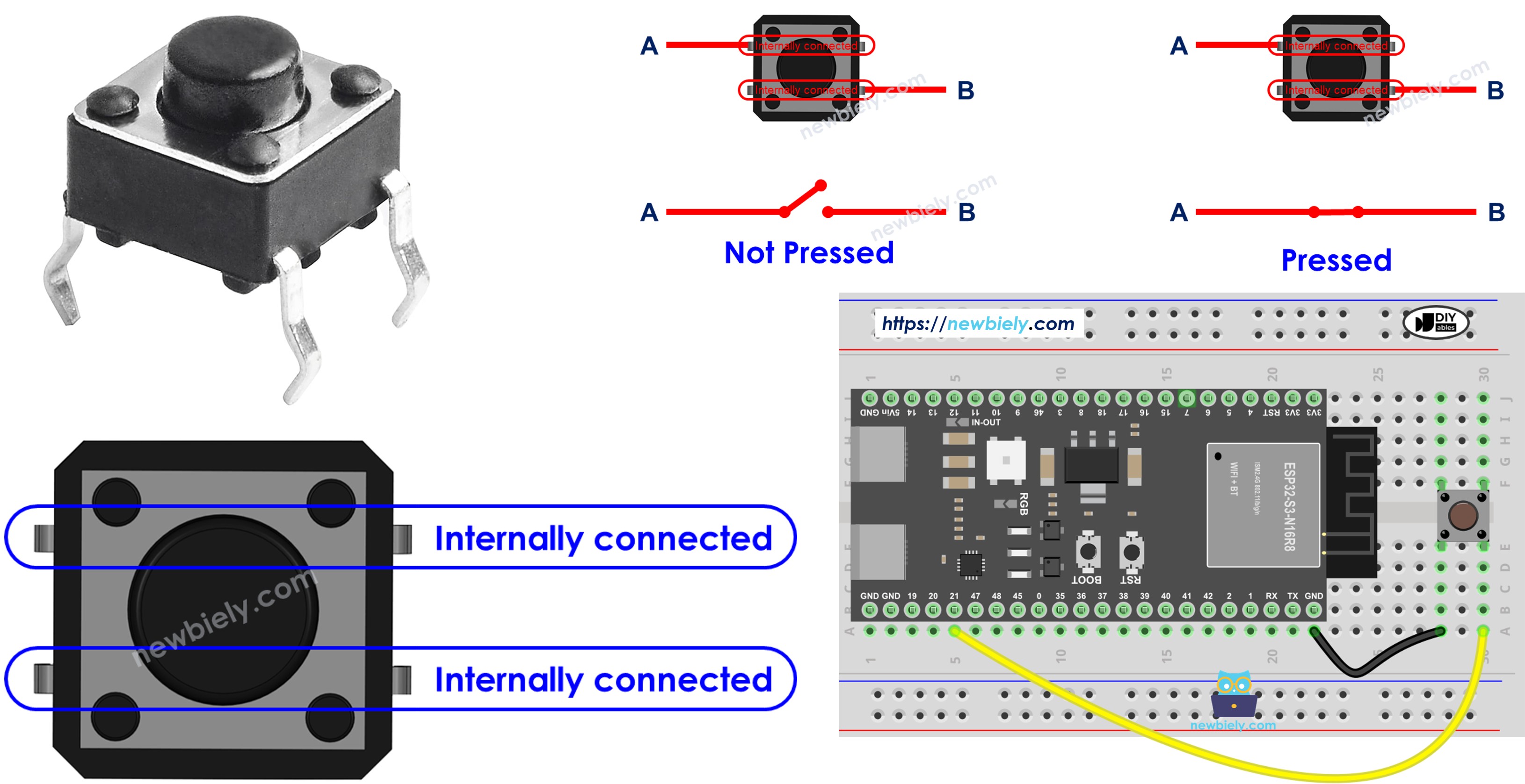
The button acts as a simple on/off switch between two pins:
- When pressed: Pin A connects to Pin B, completing the circuit
- When released: Pin A disconnects from Pin B, opening the circuit
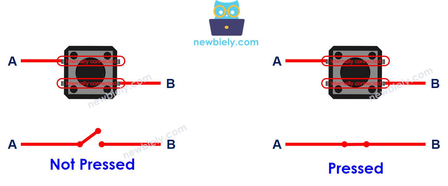
ESP32 S3 - Button
One button pin connects to an ESP32 S3 digital input pin, and the other connects to either VCC or GND depending on your chosen wiring method. Your ESP32 S3 code then reads the voltage level on that input pin to determine whether the button is currently pressed or released.
Input State and Pressing State
The relationship between the input pin voltage and the physical button state depends on how you wire the circuit. There are two standard approaches:
- Button connected to VCC:
- Requires a pull-down resistor
- Button pressed = HIGH signal
- Button released = LOW signal
- Requires a pull-up resistor
- Button pressed = LOW signal
- Button released = HIGH signal
※ NOTE THAT:
If neither a pull-down resistor nor a pull-up resistor is used, the state of the input pin is random between HIGH or LOW (unstable, unfixed) when the button is NOT pressed. This is called The "floating input problem". This results in the malfunction.
The ESP32 S3 has internal pull-up resistors built into each GPIO pin, so you can enable one with a single line of code — no external resistor required. This is the simplest and most common approach for beginners using the button-to-GND wiring method.
Wiring Diagram between Button and ESP32 S3
The following diagrams show how to connect both PCB-mount and panel-mount button types to your ESP32 S3. Both configurations use the internal pull-up resistor, so no external resistor components are needed.
Safety Notes
Always connect your button before powering the board. The GPIO7 pin on the ESP32 S3 operates at 3.3V logic — never connect the button directly to a 5V source. Using the internal pull-up with a button-to-GND configuration is the safest and most reliable approach for most applications.
Wiring with PCB-mount button:
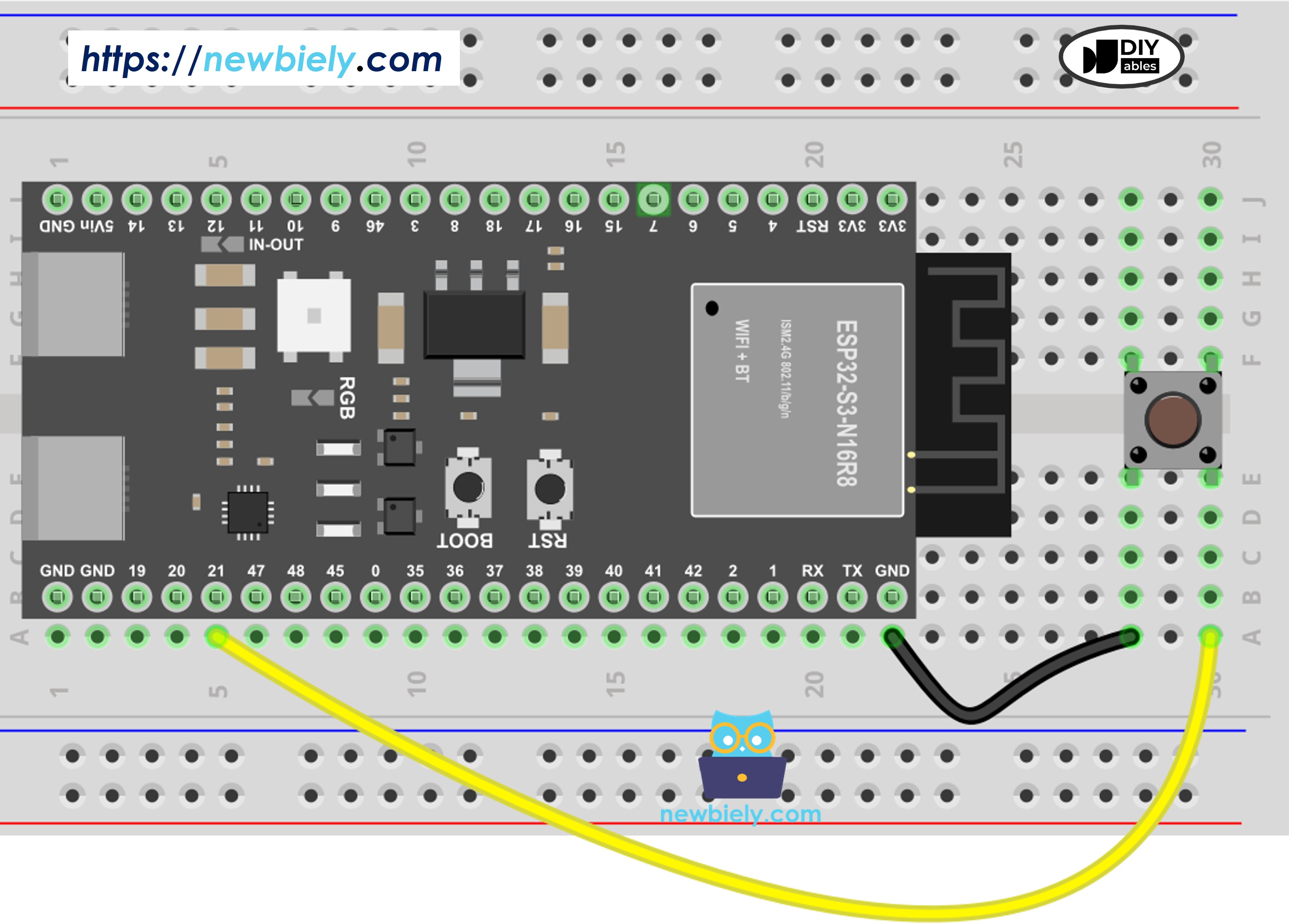
This image is created using Fritzing. Click to enlarge image
| Button Pin | ESP32 S3 Pin |
|---|---|
| Pin A | GPIO21 |
| Pin B | GND |
ESP32 S3 Code
The following sketch configures GPIO21 as an input with an internal pull-up resistor, then continuously samples the button state and prints it to the Serial Monitor every 100 milliseconds. It is the ideal starting point for understanding how the ESP32 S3 reads digital input signals from a physical button.
Detailed Instructions
- New to ESP32 S3? Complete our Getting Started with ESP32 S3 guide first.
- Wire the components: Follow the wiring diagram shown above.
- Connect your board: Plug the ESP32 S3 into your computer via USB cable.
- Open Arduino IDE: Launch the software on your computer.
- Select your board: Choose ESP32 S3 and the correct COM port.
- Upload the code: Copy the code below and paste it into Arduino IDE.
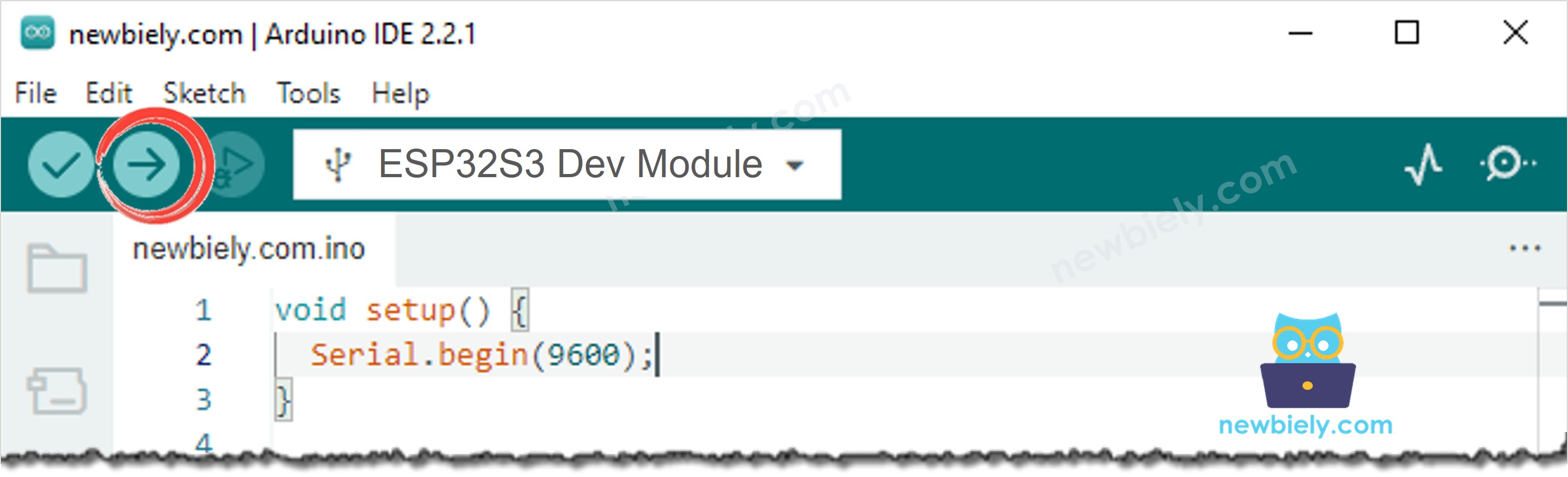
- Compile and upload: Click the Upload button in Arduino IDE.
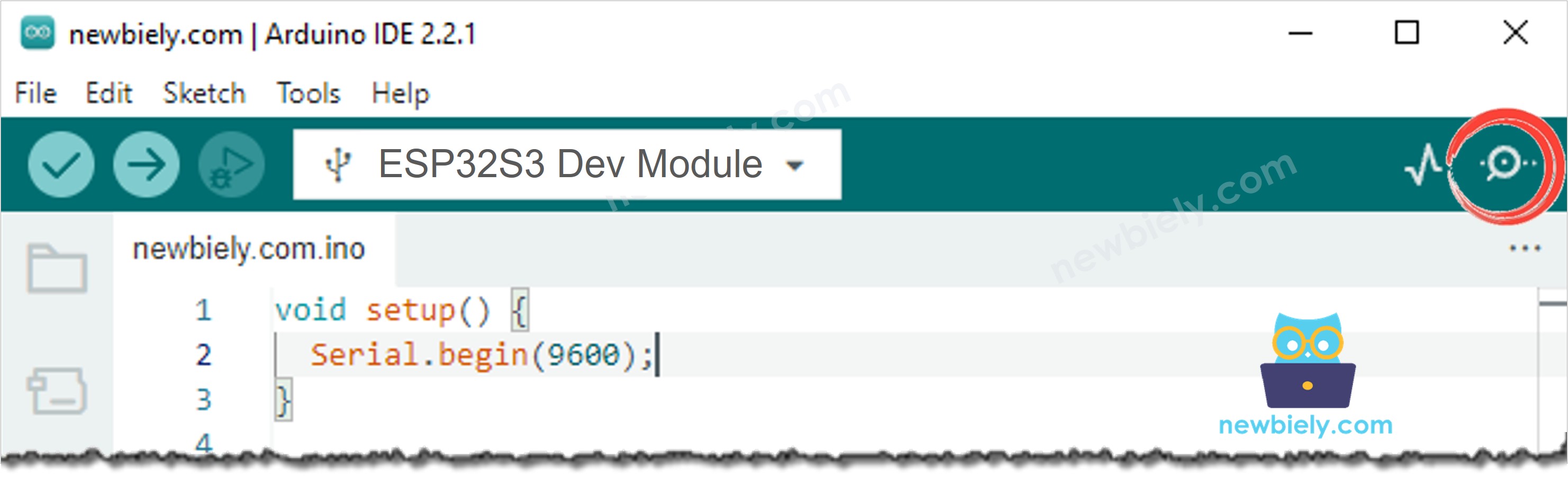
- Open Serial Monitor: Click the Serial Monitor icon in Arduino IDE.
- Test the button: Press and release the button several times.
- View results: Check the Serial Monitor output.
- Pro Tip: Keep the Serial Monitor baud rate set to 115200 to match the Serial.begin(115200) call in your sketch.
Serial Monitor Output
Note: 1 represents HIGH (button released), 0 represents LOW (button pressed).
Line-by-line Code Explanation
The above ESP32 S3 code contains line-by-line explanation. Please read the comments in the code!
Modifying ESP32 S3 Code
Let's enhance the code to detect distinct press and release events rather than simply reading the raw state. This approach is more useful in real applications where you need to trigger an action at the moment the button is pressed or released.
Detailed Instructions
- Setup environment: If this is the first time you use ESP32 S3, see how to setup environment for ESP32 S3 on Arduino IDE.
- Modify the code: Replace your previous code with the code below.
- Upload code: Compile and upload to your ESP32 S3 board.
- Open Serial Monitor: View the output window.
- Test: Press and release the button.
- Observe results: Check the Serial Monitor for event messages.
Serial Monitor Output
※ NOTE THAT:
- The Serial Monitor may print several pressed and released events even though you did only one press and release. This is a normal behavior of the button. This behavior is called the "chattering phenomenon". In some application, we need a method to eliminate it. You can learn more in ESP32 S3 - Button Debounce tutorial.
- To make it simple for beginners, especially when using multiple buttons, we created a library, called ezButton. You can learn about ezButton library here.
- When using the button module, set the pin as pinMode(BUTTON_PIN, INPUT). The module outputs LOW when unpressed and HIGH when pressed.
Application/Project Ideas
The push button is a building block that unlocks countless ESP32 S3 project possibilities, from simple indicators to complex control systems.
- LED Controller: Toggle or dim an LED with button presses to learn output control alongside input reading.
- Digital Counter: Count button presses and display the total on an OLED or Serial Monitor — great for learning state tracking.
- Quiz Buzzer: Wire multiple buttons to several ESP32 S3 GPIO pins for a multiplayer buzzer system.
- Security Alarm: Activate an alarm or send a Wi-Fi notification when a button is pressed for a set duration.
- Music Controller: Control audio playback (play, pause, skip) by mapping different press patterns to actions.
- Smart Light Switch: Replace a traditional wall switch with an ESP32 S3 button that also controls the light remotely via Wi-Fi.
Video Section
Watch the step-by-step video walkthrough for this ESP32 S3 project below.
Challenge Yourself
These exercises will deepen your understanding of button input on the ESP32 S3, progressing from basic wiring practice to more sophisticated interaction patterns.
- Beginner: Add an LED that turns ON while the button is held down and turns OFF when released.
- Beginner: Count how many times the button is pressed and print the running total to the Serial Monitor.
- Intermediate: Build a long-press detector that triggers a different action depending on whether the press is shorter or longer than one second.
- Intermediate: Implement software debouncing to eliminate false multiple-press detections without using a library.
- Advanced: Create a combination lock using three buttons — only the correct press sequence in order unlocks a simulated output.
Additional Knowledge
Understanding when to apply pull-up or pull-down resistors is an important concept for building reliable ESP32 S3 projects with digital inputs.
When to use pull-up/pull-down resistors:
- SHOULD use: Sensors with two states (open/closed) need resistors to create clear HIGH/LOW signals
- Examples: push-button, switch, magnetic contact switch (door sensor)
- SHOULD NOT use: Sensors that output voltage levels (LOW/HIGH) don't need resistors
- Examples: motion sensor, touch sensor