
ESP32 S3 - RS232
In this tutorial, we explore how to use RS232 communication with the ESP32 S3 board. We will cover everything from wiring the TTL to RS232 module to programming the ESP32 S3 to send and receive serial data over RS232.
What you'll build:
- Connect an ESP32 S3 to a TTL to RS232 module
- Configure the ESP32 S3 UART to communicate over RS232
- Send data from the ESP32 S3 to an RS232 device
- Receive and echo data from an RS232 device back through the Serial Monitor
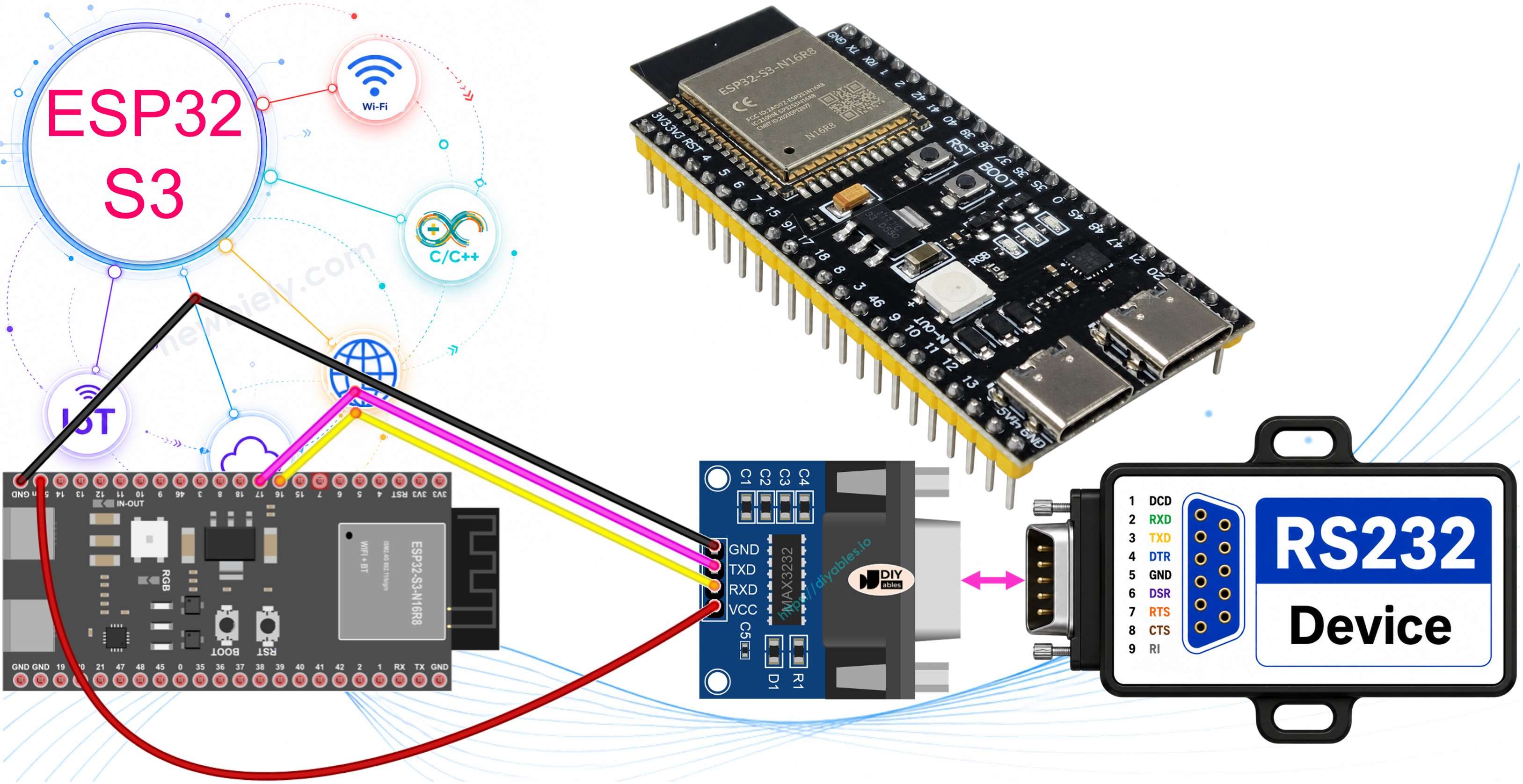
Hardware Preparation
Or you can buy the following kits:
| 1 | × | DIYables ESP32 S3 Starter Kit (ESP32 S3 included) | |
| 1 | × | DIYables Sensor Kit (18 sensors/displays) |
Additionally, some of these links are for products from our own brand, DIYables .
Overview of TTL to RS232 Module
When using serial communication with Serial.print(), Serial.read(), and Serial.write() functions on the ESP32 S3, the board outputs data through its TX pin and reads data from its RX pin at TTL voltage levels. TTL signals are suitable for short-distance communication only, so when you need to transmit data over longer distances or connect to legacy industrial equipment, a signal converter such as the TTL to RS232 module is required. The TTL to RS232 module converts TTL signals to the RS232 standard and vice versa, making it straightforward to interface the ESP32 S3 with RS232-compatible devices.
Key Specifications
The TTL to RS232 module bridges two electrical standards:
- Operates with both 5V and 3.3V TTL logic levels
- Uses a DB9 female D-Sub connector for the RS232 interface
- Typically based on the MAX3232 chip for 3.3V compatibility
Pinout
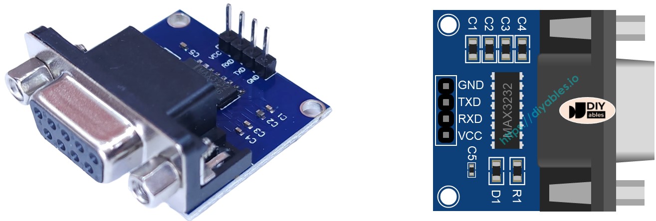
The RS232 to TTL module exposes two distinct interfaces — a TTL side that connects to the ESP32 S3, and an RS232 side that connects to the serial device.
- VCC pin — power pin, connect to VCC (5V or 3.3V)
- GND pin — power pin, connect to GND (0V)
- RXD pin — data pin, connect to a TX pin of the ESP32 S3
- TXD pin — data pin, connect to a RX pin of the ESP32 S3
- DB9 female connector — RS232 interface, connect to the serial device
Wiring Diagram
Connect the TTL to RS232 module to the ESP32 S3 by linking the module's VCC to 3.3V, GND to GND, RXD to an ESP32 S3 TX pin, and TXD to an ESP32 S3 RX pin. Double-check your TX/RX cross-connection before powering the circuit to avoid communication issues.
Safety Notes
The ESP32 S3 operates at 3.3V logic levels. Ensure your TTL to RS232 module is compatible with 3.3V (modules based on the MAX3232 are recommended). Avoid connecting the module's VCC to 5V if the module is not rated for it, as this could damage the ESP32 S3 I/O pins.
| ESP32 S3 | TTL to RS232 Module |
|---|---|
| 3.3V | VCC |
| GND | GND |
| GPIO17 (TX) | RXD |
| GPIO18 (RX) | TXD |
- How to connect ESP32 S3 and RS232 to TTL module using breadboard
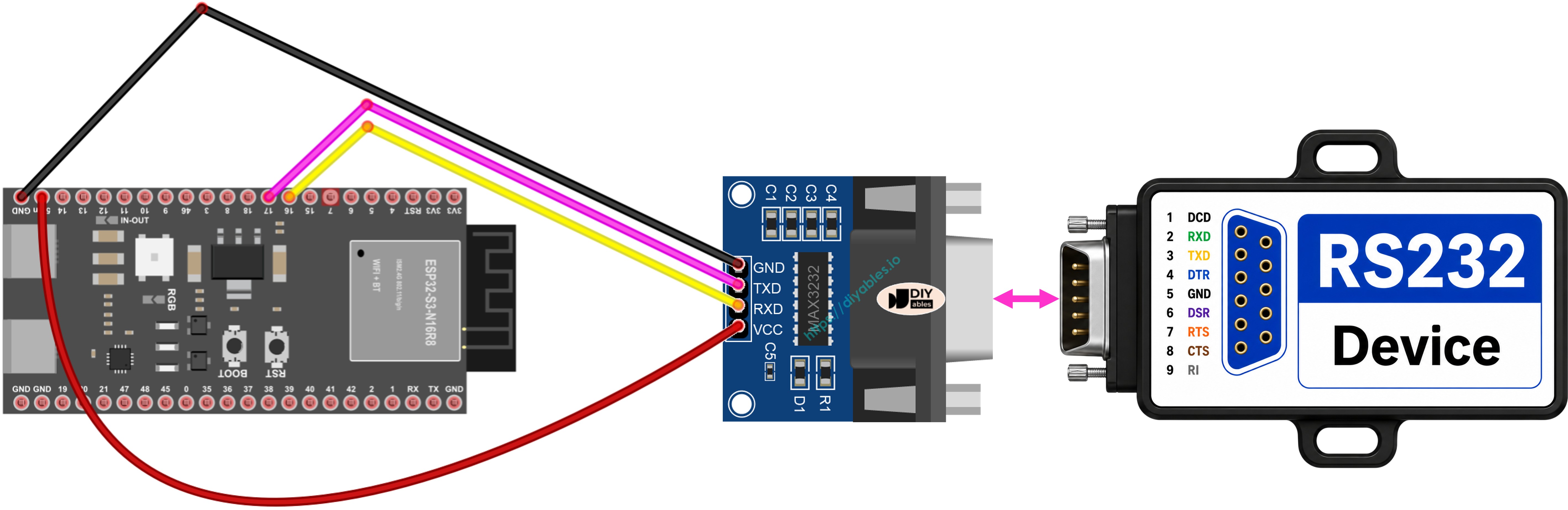
This image is created using Fritzing. Click to enlarge image
How To Program ESP32 S3 to Use the RS232 Module
Programming the ESP32 S3 for RS232 communication follows the standard Arduino Serial API, with the conversion handled transparently by the TTL to RS232 module. You initialize a hardware serial port, configure the baud rate, and then use familiar read() and write() functions to exchange data. The following code shows how to initialize both the Serial Monitor and the RS232 serial port on the ESP32 S3.
- Initializes the Serial interface:
- To read data come from RS232, you can use the following functions:
- To write data to RS232, you can use the following functions:
- And more functions to use with RS232 in Serial reference
ESP32 S3 Code for RS232
Detailed Instructions
Follow these steps to get your ESP32 S3 RS232 project running successfully.
- New to ESP32 S3? Complete our Getting Started with ESP32 S3 guide first.
- Click to the ESP32 S3 Code for RS232 section above, copy the code, and open it in the Arduino IDE.
- Wire the TTL to RS232 module to the ESP32 S3 following the wiring diagram above.
- Connect the ESP32 S3 to your PC via USB Type-C cable.
- Select the correct board and COM port in the Arduino IDE.
- Click the Upload button to compile and flash the code.
- Open the Serial Monitor at 9600 baud to observe output.
- Connect the RS232 device (or RS232-to-USB cable) and send test data to verify two-way communication.
- Pro Tip: If no data appears in the Serial Monitor, double-check your TX/RX cross-connections — a swapped pair is the most common wiring mistake with RS232 modules.
Serial Monitor Output
Once the ESP32 S3 is running and connected to an RS232 device via the TTL to RS232 module, you should see output similar to the following in the Arduino IDE Serial Monitor.
Applications
RS232 communication bridges the ESP32 S3 to a wide range of legacy and industrial equipment that predates modern digital interfaces.
- Industrial PLC Integration: Connect the ESP32 S3 to programmable logic controllers that use RS232 for configuration or data readout.
- Legacy Instrument Control: Interface with older lab equipment such as oscilloscopes, signal generators, or power supplies that expose an RS232 port.
- GPS Receiver Communication: Many GPS modules output NMEA sentences over RS232, which the ESP32 S3 can parse for location data.
- Point-of-Sale Terminals: Exchange transaction data with receipt printers and barcode scanners that use RS232.
- Building Automation: Read data from HVAC controllers, energy meters, and access control panels with RS232 interfaces.
- Robotics Serial Bus: Use RS232 as a robust communication link between the ESP32 S3 and servo controllers or motor drivers in noisy environments.
Video Tutorial
Watch the step-by-step video walkthrough for this ESP32 S3 project below.
Challenges
These challenges will help you deepen your understanding of RS232 communication with the ESP32 S3 and push your project further.
- Beginner: Modify the code to send a "Hello from ESP32 S3!" message over RS232 every five seconds and confirm receipt on a terminal program such as PuTTY or Tera Term.
- Intermediate: Implement a simple command-response protocol where the ESP32 S3 reads a command string from the RS232 device and replies with different responses depending on the command received.
- Advanced: Build a data logger that receives structured sensor readings over RS232, parses the values, and stores them to an SD card or uploads them to a cloud service via the ESP32 S3's Wi-Fi capabilities.