
ESP32 S3 - Joystick
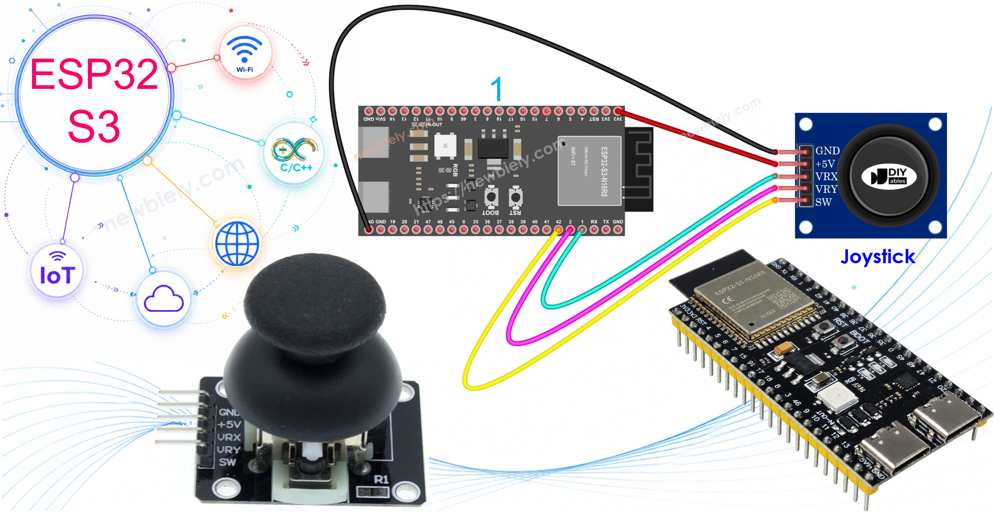
Learn how to connect and program a joystick module with your ESP32 S3 board. This tutorial walks you through wiring, reading analog values from both axes, detecting button presses, and converting raw readings into directional commands.
What you'll build:
- A joystick reader that outputs X and Y analog values to the Serial Monitor
- A combined joystick and button reader using the ezButton library
- A directional command converter (MOVE LEFT / RIGHT / UP / DOWN)
- A foundation for servo motor control and robot direction projects
Hardware Preparation
Or you can buy the following kits:
| 1 | × | DIYables ESP32 S3 Starter Kit (ESP32 S3 included) | |
| 1 | × | DIYables Sensor Kit (18 sensors/displays) |
Additionally, some of these links are for products from our own brand, DIYables .
Overview of Joystick Sensor
The joystick sensor is an analog input module that uses two internal potentiometers mounted perpendicular to each other to detect position across two dimensions. It also includes a built-in pushbutton that activates when the joystick shaft is pressed downward. On the ESP32 S3, both analog axes are read as values from 0 to 4095, giving you fine-grained control over movement detection.
Key Specifications
The joystick outputs X-axis position on the VRX pin and Y-axis position on the VRY pin, each as an analog voltage between 0V and 3.3V that the ESP32 S3 converts to a 12-bit integer (0 to 4095). The center resting position of each axis typically reads near the midpoint, around 2048. The built-in pushbutton on the SW pin is normally HIGH when using an internal pull-up resistor and pulls LOW when the joystick shaft is pressed. The module is compatible with 3.3V logic, making it a natural fit for the ESP32 S3.
Pinout
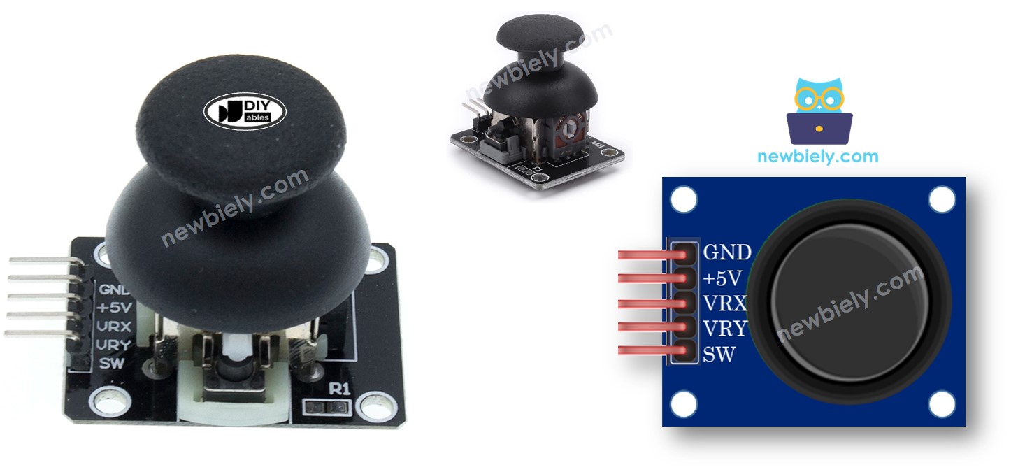
The joystick module has five pins for connecting to your ESP32 S3:
- GND: Connect to ground (0V)
- VCC: Connect to power supply (3.3V)
- VRX: Analog output for horizontal position (X-axis)
- VRY: Analog output for vertical position (Y-axis)
- SW: Digital output from internal pushbutton (normally HIGH with pull-up resistor, LOW when pressed)
How It Works
X-axis movement (left/right):
- Moving joystick left/right changes voltage on VRX pin
- Voltage ranges from 0V (left) to 3.3V (right)
- ESP32 S3 reads analog values from 0 to 4095
- Value is proportional to horizontal thumb position
Y-axis movement (up/down):
- Moving joystick up/down changes voltage on VRY pin
- Voltage ranges from 0V (up) to 3.3V (down)
- ESP32 S3 reads analog values from 0 to 4095
- Value is proportional to vertical thumb position
Diagonal movement:
- Both VRX and VRY voltages change simultaneously
- Each axis outputs proportional to position projection
- Creates smooth 2D coordinates for any direction
Pushbutton function:
- Press joystick down to activate internal button
- With pull-up resistor, SW pin outputs 3.3V normally
- Pressing button pulls SW pin to 0V (GND)
- ESP32 S3 reads HIGH when released, LOW when pressed
Wiring Diagram
Connect the joystick module to the ESP32 S3 using the wiring diagram below, keeping the VCC wire connected to the 3.3V pin to stay within the board's logic level. Double-check the GND connection before powering up to avoid floating readings on the analog pins.
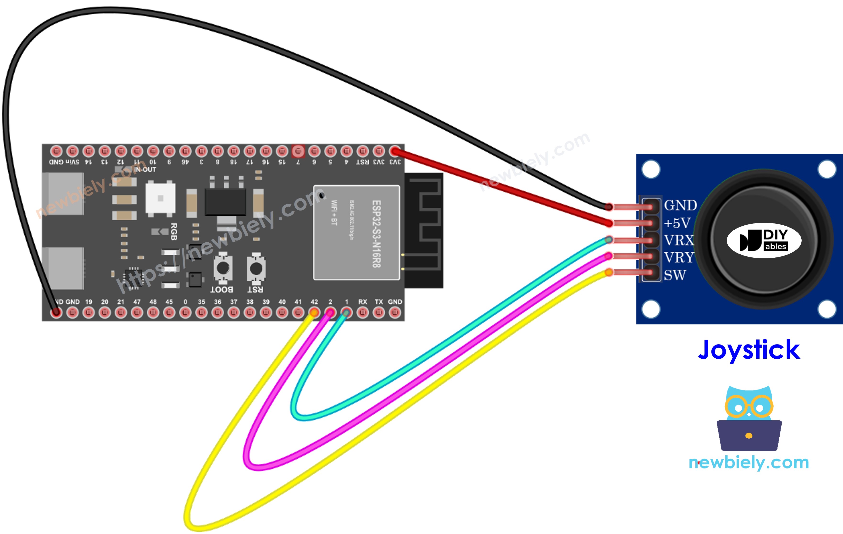
This image is created using Fritzing. Click to enlarge image
Safety Notes
Always power the joystick module from the ESP32 S3's 3.3V pin, never from 5V, as the analog input pins on the ESP32 S3 are not 5V tolerant and applying higher voltage can permanently damage the ADC. Use short, direct jumper wires for the analog signal lines (VRX and VRY) to minimize noise in the readings.
| Joystick Pin | ESP32 S3 Pin |
|---|---|
| GND | GND |
| VCC | 3.3V |
| VRX | GPIO1 |
| VRY | GPIO2 |
| SW | GPIO42 |
How To Program For Joystick
Reading the joystick on the ESP32 S3 involves two separate techniques: analogRead() for the X and Y axes, and a debounced digital read for the pushbutton. The analogRead() function returns a 12-bit integer between 0 and 4095, representing the full voltage range across each potentiometer axis. For the button, the ezButton library simplifies debouncing so you get clean state transitions without writing extra logic.
Reading analog axes (X, Y coordinates):
- Use analogRead() function for VRX and VRY pins
- Returns values from 0 to 4095 on ESP32 S3
- Simple one-line read for each axis
Reading digital button (SW pin):
- Treat as standard pushbutton input
- Use ezButton library for easy debouncing
- Library enables internal pull-up resistor automatically
- See ESP32 S3 - Button tutorial for details
- Button code examples provided in following sections
Converting values to commands:
- Raw analog values may need conversion for control applications
- Convert to directional commands (UP, DOWN, LEFT, RIGHT)
- Map to servo angles for pan-tilt mechanisms
- Scale to motor speed values
- Example conversion codes provided below
ESP32 S3 Code
The following sections provide multiple ESP32 S3 joystick code examples, each building on the previous one. You will start by reading raw X and Y values, then add button detection, and finally convert the analog readings into human-readable directional commands. Each example can be uploaded and tested independently.
What these code examples demonstrate:
- Reading X and Y analog values from joystick
- Reading analog values plus pushbutton state
- Converting analog readings to directional commands
- Mapping joystick position to servo motor angles
- Practical applications for game and robot control
Reads analog values from joystick
Detailed Instructions
- New to ESP32 S3? Complete our Getting Started with ESP32 S3 guide first.
- Wire the components: Follow the wiring diagram shown above to connect the joystick to your ESP32 S3.
- Connect the board: Plug your ESP32 S3 into your computer using a USB Type-C cable.
- Open Arduino IDE: Launch the Arduino IDE on your computer.
- Select board and port: Choose ESP32 S3 from the board menu and select the correct COM port.
- Upload the code: Copy the code above, paste it into Arduino IDE, and click the Upload button.
- Test the joystick: Push the joystick's thumb maximally to its limits in all directions.
- Rotate the joystick: Move the thumb in a complete circle (clockwise or counterclockwise).
- Open Serial Monitor: Check the output to see X and Y coordinate values.
- Identify directions: Watch the Serial Monitor while rotating to identify which positions correspond to left/right/up/down (X=0 is left, Y=0 is up).
- Pro Tip: Mark the joystick base with arrows showing the coordinate directions for easy reference in future projects.
※ NOTE THAT:
You may notice the analog values are not perfectly linear with joystick movement. This is due to the ESP32 S3's ADC characteristics, not the joystick itself. See the ADC calibration note at the end of this tutorial for more information.
Reads analog values and reads the button state from a joystick
Detailed Instructions
- New to ESP32 S3? Complete our Getting Started with ESP32 S3 guide first.
- Install ezButton library: Click the Library Manager icon in the left navigation bar of Arduino IDE.
- Search for library: Type "ezButton" in the search box.
- Find the library: Locate the button library by ArduinoGetStarted.com.
- Install: Click the Install button to add ezButton library to your Arduino IDE.
- Search for ezButton created by ArduinoGetStarted.com and click the Install button.
- Upload the code: Copy the code above into Arduino IDE and click Upload.
- Test X/Y movement: Push the joystick thumb left, right, up, and down.
- Test button: Press the joystick thumb down from the top to activate the button.
- View results: Open Serial Monitor to see X, Y values and button state changes.
- Pro Tip: The ezButton library automatically handles debouncing, giving you clean button press detection without extra code.
Converts analog value to MOVE LEFT/RIGHT/UP/DOWN commands
Detailed Instructions
- New to ESP32 S3? Complete our Getting Started with ESP32 S3 guide first.
- Upload the code: Copy the command conversion code into Arduino IDE and click Upload.
- Move the joystick: Push the thumb in different directions - left, right, up, down, and diagonal.
- Check Serial Monitor: Open Serial Monitor to see directional command outputs.
- Test diagonals: Move to corners to see multiple simultaneous commands (e.g., "UP + LEFT").
- Pro Tip: Adjust the threshold values in the code to make the joystick more or less sensitive to your movements.
※ NOTE THAT:
The joystick can output zero, one, or two commands simultaneously. For example, when pushed to upper-left corner, it outputs both "MOVE UP" and "MOVE LEFT" at the same time, perfect for diagonal movement in games and robots.
Converts analog values to angles to control two servo motors
For detailed instructions on controlling servo motors with your ESP32 S3 joystick, see the complete tutorial: ESP32 S3 - Joystick controls Servo Motor
What you'll learn in the servo tutorial:
- Mapping joystick X/Y values to servo angles (0-180 degrees)
- Controlling pan-tilt camera mechanisms
- Building interactive robotic arm controls
- Real-time servo response to joystick movement
※ NOTE THAT:
Important ADC Accuracy Information:
This tutorial uses the analogRead() function to read values from an ADC (Analog-to-Digital Converter) connected to a sensor or component. The ESP32 S3's ADC is suitable for projects that do not require high accuracy. However, for projects needing precise measurements, keep the following in mind:
- The ESP32 S3's ADC is not perfectly accurate and might require calibration for correct results. Each ESP32 S3 board can vary slightly, so calibration is necessary for each individual board.
- Calibration can be challenging, especially for beginners, and might not always yield the exact results you want.
For projects requiring high precision, consider using an external ADC (e.g ADS1115) with the ESP32 S3 or using another Arduino, such as the Arduino Uno R4 WiFi, which has a more reliable ADC. If you still want to calibrate the ESP32 S3's ADC, refer to the ESP32 ADC Calibration Driver.
Application and Project Ideas
The ESP32 S3 joystick setup opens the door to a wide range of interactive and embedded control projects. Here are some ideas to inspire your next build:
- Wireless RC car: Build a wireless RC car with directional control using ESP-NOW.
- Pan-tilt camera: Create a pan-tilt camera system for video tracking using two servo motors.
- Game controller: Design a game controller for Arduino-based games running on an OLED display.
- Robot arm: Control a robot arm with intuitive joystick movements mapped to servo angles.
- Drone interface: Make a drone flight controller interface with adjustable sensitivity.
- Wheelchair control: Build an electric wheelchair joystick control system with speed ramping.
- Arcade console: Create an arcade-style gaming console with joystick and button input.
- Camera slider: Design a camera slider with precise positioning control driven by stepper motors.
Video Tutorial
Watch the step-by-step video walkthrough for this ESP32 S3 project below.
Challenge Yourself
Completing the examples above gives you a solid foundation for joystick-based projects on the ESP32 S3. Try the following challenges to deepen your understanding and push your skills further:
- Beginner: Add LED indicators that light up based on joystick direction (4 LEDs for up/down/left/right).
- Beginner: Display joystick X and Y values on an OLED or LCD screen instead of Serial Monitor.
- Intermediate: Create a drawing program that plots joystick movement on an OLED display in real-time.
- Intermediate: Add speed control by mapping joystick distance from center to motor speed values.
- Advanced: Build a wireless joystick controller using ESP-NOW to control another ESP32 S3 remotely.
- Advanced: Implement gesture recognition that detects specific joystick movement patterns (circles, figure-8s, etc.).