
ESP32 S3 Camera - Save Photo to SD Card When Door Opens
This tutorial instructs you how to build a door camera with the ESP32 S3. A magnetic door sensor watches your door. The moment somebody opens it, the ESP32 S3 takes a photo and saves it to a microSD card. The board works alone. It does not need WiFi, and it does not need a computer.
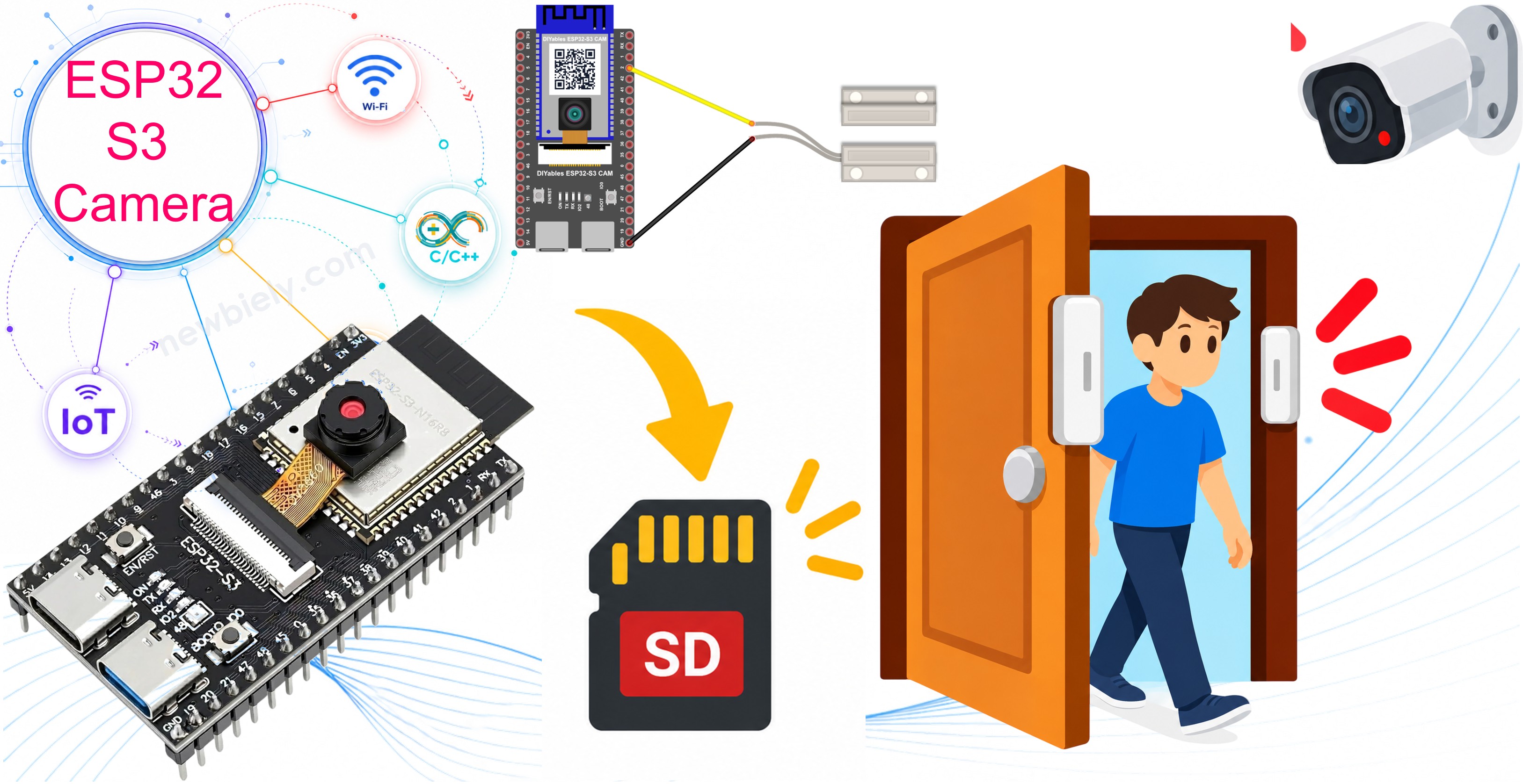
What you'll build:
- An ESP32 S3 camera with a magnetic door sensor
- A photo saved to the microSD card every time the door is opened
- Clean detection, so one door movement saves exactly one photo
- A door camera that works with no internet at all
Hardware Preparation
Or you can buy the following kits:
| 1 | × | DIYables Sensor Kit (18 sensors/displays) |
Additionally, some of these links are for products from our own brand, DIYables .
※ NOTE THAT:
The ESP32 S3 camera board has 40 pins, but the screw terminal block and the breakout board have 44 pins. They still work together. Put the camera board in the center of the 44-pin board, so 2 pins stay free on the left side and 2 pins stay free on the right side.
The screw terminal block lets you connect wires with a screwdriver, with no soldering. The breakout board gives you easy pin headers for a breadboard.
Overview of Door Sensor
A door sensor has two parts:
- A small plastic box with two wires. This part holds a reed switch. You put it on the door frame.
- A second plastic box with no wires. This part holds a magnet. You put it on the door itself.
When the door is closed, the magnet sits next to the reed switch and closes it. When the door opens, the magnet moves away, and the switch opens again.
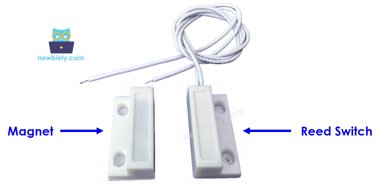
For more detail about the door sensor, see the ESP32 S3 - Door Sensor tutorial.
Key Specifications
| Item | Value |
|---|---|
| Type | Magnetic reed switch (normally open) |
| Wires | 2, and they have no direction |
| Working gap | about 15 mm to 25 mm |
| Power | None. It is only a switch. |
※ NOTE THAT:
The two wires have no plus and no minus. You can connect them either way round.
How The ESP32 S3 Reads The Door
The door sensor is only a switch, so the ESP32 S3 must give it a voltage itself. We use the internal pull-up resistor:
With INPUT_PULLUP, the pin is HIGH when nothing pulls it down. The table shows what happens:
| Door | Magnet | Reed switch | Pin reads |
|---|---|---|---|
| Closed | Next to the switch | Closed (connected to GND) | LOW |
| Open | Away from the switch | Open (nothing connected) | HIGH |
So in the code:
Why The Code Waits 50 Milliseconds
A metal switch never changes cleanly. In the first milliseconds it jumps between open and closed many times. This is called bouncing. Without protection, one door movement would save five photos.
The code waits until the value stays the same for 50 milliseconds:
Motion Sensor or Door Sensor?
Both build a small security camera, but they are not the same:
| Door Sensor | Motion Sensor (PIR) | |
|---|---|---|
| Sees | Only the door opening | Any warm body that moves |
| False alarms | Almost never | Sometimes (heaters, windows, animals) |
| Warm-up time | None | 30 to 60 seconds |
| Needs power | No | Yes, 5V |
| Works through glass | Yes | No |
A door sensor is the better choice when you want to know about one exact event. See also the ESP32 S3 Camera - Save Photo to SD Card When Motion Detected tutorial.
Overview of microSD Card on ESP32 S3
The ESP32 S3 camera board has a microSD card slot. The card is a very good place for photos, because:
- A photo is too big for the memory of the ESP32 S3. The card can hold thousands of photos.
- The card keeps the photos when the power goes off.
- You can take the card out and read it on your computer.
Card Requirements
| Item | Value |
|---|---|
| Card type | microSD or microSDHC |
| Size | Up to 32 GB works best |
| File system | FAT32 |
| Speed class | Class 10 or faster |
※ NOTE THAT:
A card bigger than 32 GB usually comes with the exFAT file system. The ESP32 S3 cannot read exFAT. Format the card as FAT32 before you use it.
The card slot is already connected inside the board. You do not need to wire it. But the code must know the pins:
| Card Pin | ESP32 S3 Pin | Meaning |
|---|---|---|
| CLK | GPIO39 | Clock |
| CMD | GPIO38 | Commands |
| D0 | GPIO40 | Data |
※ NOTE THAT:
The camera uses the other card pins, so the code must open the card in 1-bit mode. That is the word true in SD_MMC.begin("/sdcard", true). Learn more in the ESP32 S3 Camera - Save Photo to SD Card Every Few Seconds tutorial.
Wiring Diagram between Door Sensor and ESP32 S3
Connect the two wires of the door sensor to your ESP32 S3.
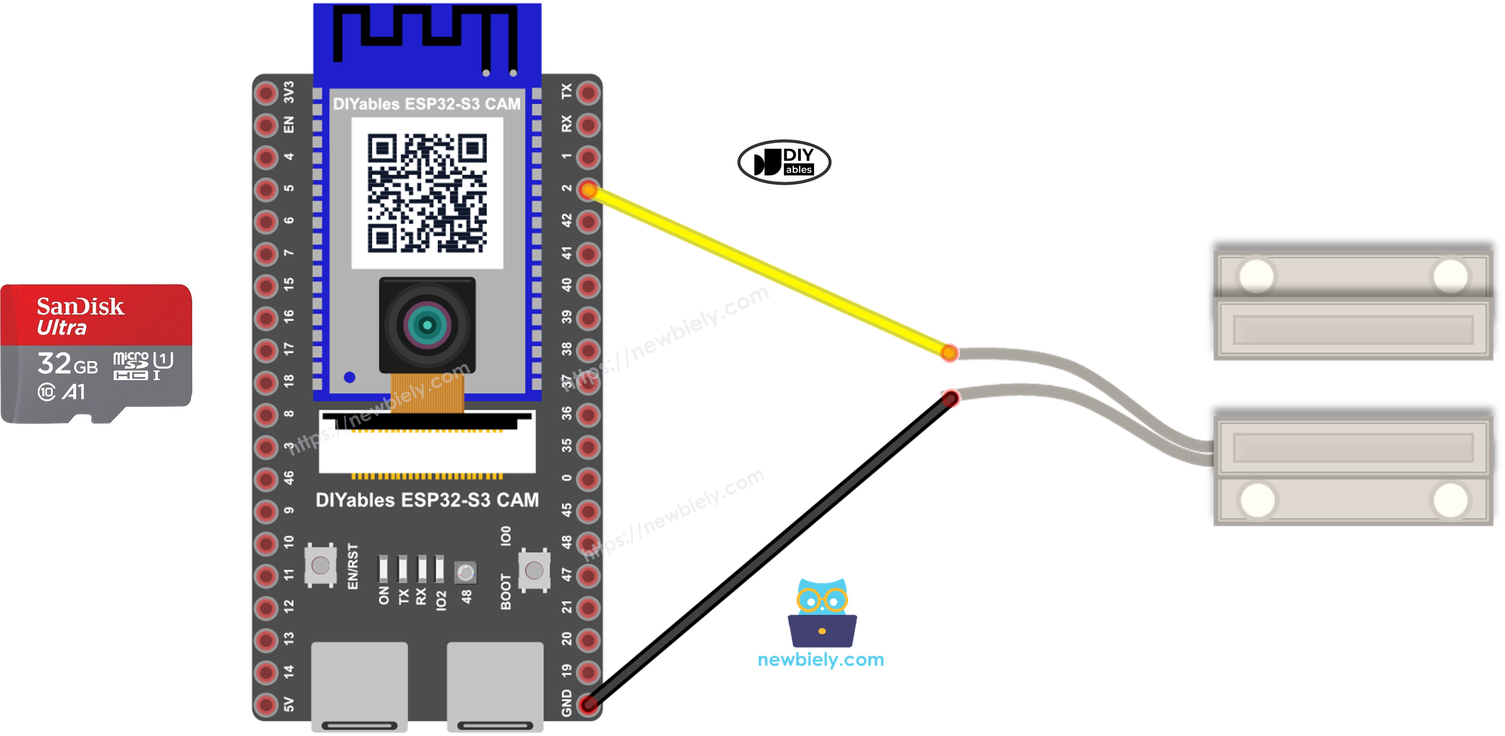
This image is created using Fritzing. Click to enlarge image
| Door Sensor Wire | ESP32 S3 Pin |
|---|---|
| First wire | GPIO2 |
| Second wire | GND |
Then put the microSD card into the slot, and put the two parts of the sensor on your door:
- Put the part with the wires on the door frame.
- Put the part without wires on the door itself.
- Move the door until the two parts are next to each other. They must almost touch, with a gap smaller than 15 mm.
- Point the camera at the door.
Safety Notes
The door sensor needs no power. Do not connect it to 5V or to 3.3V. One wire goes to GPIO2, the other goes to GND. Nothing can break, because it is only a switch.
Never take the microSD card out while the board is writing a photo. Always unplug the USB cable first, wait two seconds, then take the card out.
Do not use a camera pin for the sensor. The camera already uses GPIO4, 5, 6, 7, 8, 9, 10, 11, 12, 13, 15, 16, 17 and 18. The card slot uses GPIO38, 39 and 40. GPIO2 is free, so we use it.
Arduino IDE Settings for ESP32 S3 Camera
The camera does not work with the default settings of the Arduino IDE. You must change some items in the Tools menu before you upload the code.
| Tools Menu Item | Select This |
|---|---|
| Board | ESP32S3 Dev Module |
| Flash Size | 16MB (128Mb) |
| PSRAM | OPI PSRAM |
| Partition Scheme | Huge APP (3MB No OTA/1MB SPIFFS) |
| CPU Frequency | 240MHz (WiFi) |
| USB Mode | Hardware CDC and JTAG |
| Upload Mode | UART0 / Hardware CDC |
| Upload Speed | 921600 |
| USB CDC On Boot | Enabled |
※ NOTE THAT:
PSRAM must be OPI PSRAM, and Partition Scheme must be Huge APP. Change Flash Size first, because the list of Partition Scheme options changes after that.
How To Program the Door Camera
You do not need to install any library. SD_MMC and esp_camera are already inside the ESP32 board package.
- Set the sensor pin as an input with a pull-up resistor.
- Read the door one time in setup(), so the code knows the state at the start.
- In loop(), wait until the value is stable, then look for the change to open.
※ NOTE THAT:
The code saves a photo only when the door opens. Nothing happens when the door closes again. Do you want a photo for both? Then call takeAndSavePhoto() in the else part too.
- Start the microSD card in 1-bit mode.
- Give every photo a different name, so a new photo never writes over an old one.
- When the board restarts, the counter starts at 1 again. To keep the old photos, look for the first free name:
- Open a file, write the photo, and close the file.
※ NOTE THAT:
You must call file.close(). If you forget it, the photo stays in the memory and never reaches the card.
ESP32 S3 Code
The following code saves a photo named door_00001.jpg, door_00002.jpg, and so on, every time the door is opened. The quiet time is 3 seconds. To change it, change the line #define QUIET_TIME 3000.
Detailed Instructions
- New to ESP32 S3? Complete our Getting Started with ESP32 S3 guide first.
- Format your microSD card as FAT32 on your computer.
- Unplug the USB cable. Put the card into the slot, and connect the two wires of the door sensor as in the table above.
- Copy the above code and paste it into the Arduino IDE.
- Change the settings in the Tools menu. See the table above.
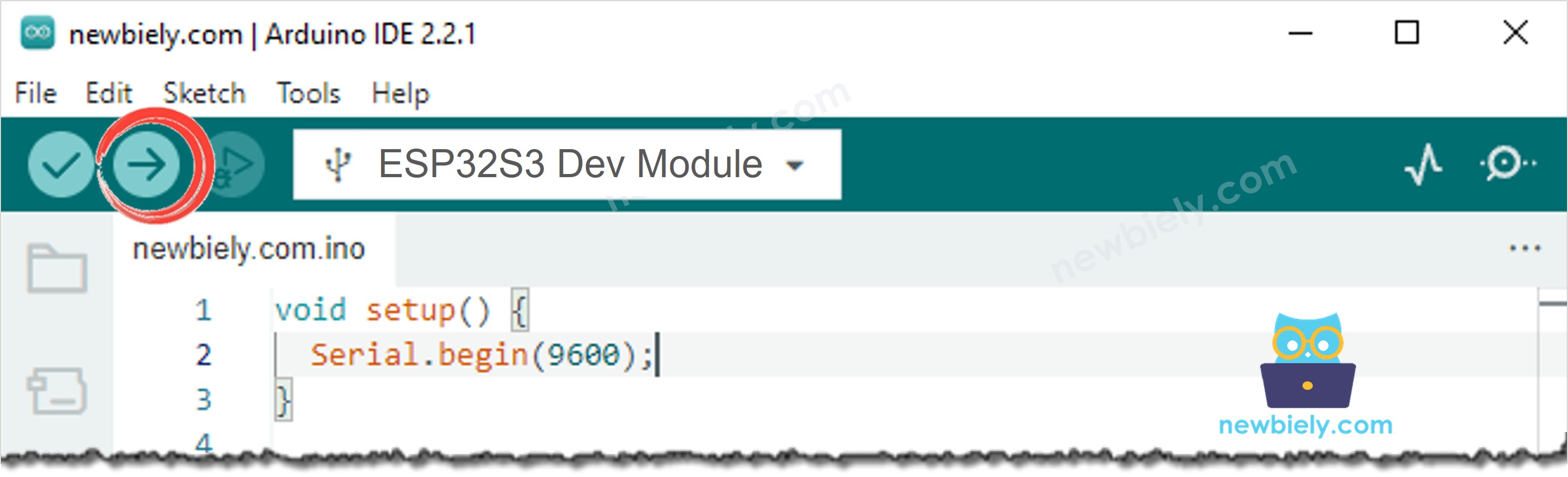
- Compile and upload the code to the ESP32 S3 board by clicking the Upload button in Arduino IDE.
- Open the Serial Monitor in Arduino IDE.
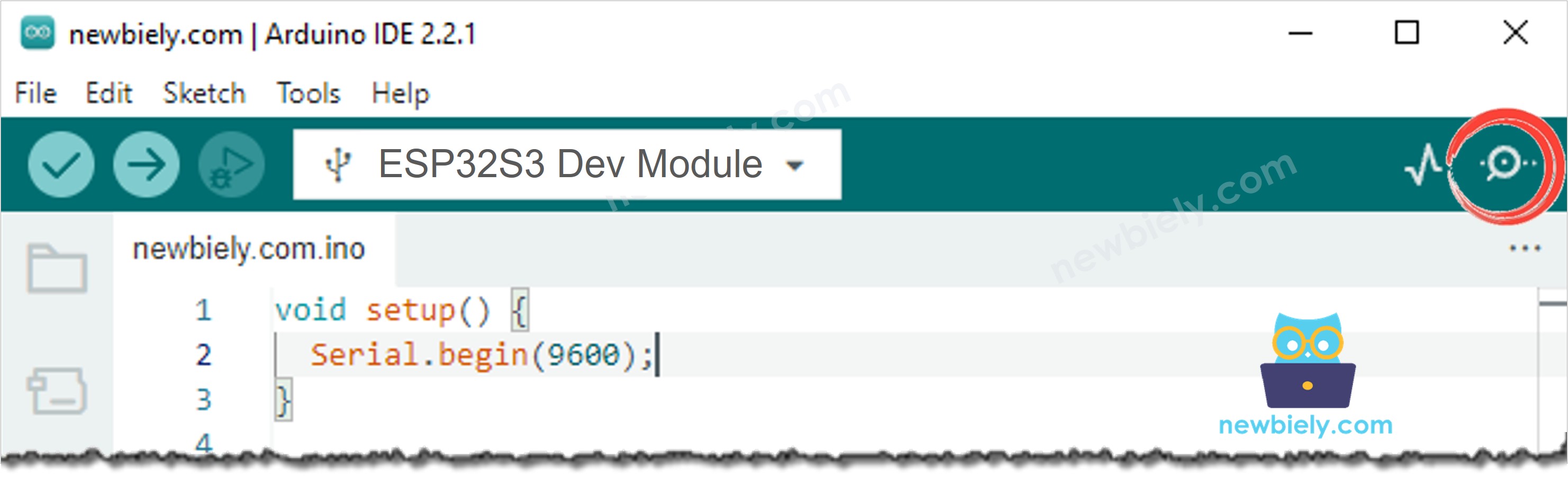
- Press the RESET button one time.
- Put the two parts of the sensor next to each other. The Serial Monitor says the door is closed.
- Move the two parts away from each other, like an opening door.
- Look at the Serial Monitor. You see The door is open! and the name of the photo.
- Unplug the USB cable, take the card out, and read the photos on your computer.
Serial Monitor
The following readings were captured in 2026:
When the door is opened again too quickly, the code says so and saves nothing:
Troubleshooting
The Serial Monitor always says the door is open, even when it is closed.
- The two parts are too far apart. They must almost touch, with a gap smaller than 15 mm.
- Check the wire on GPIO2 and the wire on GND.
- Some door sensors are "normally closed" instead of "normally open". Then the two lines #define DOOR_CLOSED LOW and #define DOOR_OPEN HIGH must swap their values.
The Serial Monitor always says the door is closed.
The two wires are probably touching each other, or one wire is on the wrong pin. One wire goes to GPIO2, the other to GND.
One door movement saves two or three photos.
Increase DEBOUNCE_TIME from 50 to 150.
The Serial Monitor shows SD card not found.
Format the card as FAT32, use a card of 32 GB or smaller, and push the card in again. You can also check the three pin numbers at the top of the code against the drawing of your board.
The Serial Monitor shows No SD card inside the slot.
The board found the slot but no card. Push the card in again, or try another card.
The Serial Monitor shows Cannot write the file.
The card is full, or the card is locked, or the card is broken. Check the free space on your computer.
The photo is dark.
The camera cannot see in the dark. Add a light near the door, or a lamp that switches on with the door.
The Serial Monitor shows nothing after the boot messages.
If your USB cable is in the port named UART, set USB CDC On Boot to Disabled. If it is in the port named USB, set it to Enabled.
The Serial Monitor shows Camera init failed with error 0x105.
Set PSRAM to OPI PSRAM in the Tools menu, and check the flat cable of the camera.
Applications
A door sensor gives you one clear event with almost no false alarms, and the microSD card means no WiFi, no internet and no monthly payment. Here are practical projects you can build with this code:
- Offline front door camera: See who opened your front door while you were away, with no internet connection at all.
- Parcel box camera: Keep a photo of the person who opens your parcel box or your mailbox.
- Tool box, safe or locker record: Get a picture every time somebody opens it, even in a place with no WiFi.
- Garage and shed camera: Know who opened your garage door at night.
- Medicine cabinet watcher: Keep a photo when a child opens a cabinet that must stay closed.
- Server rack and control cabinet: Keep a photo record of everybody who opens a cabinet at work.
- Holiday home door camera: Leave it in an empty house for weeks, and read the card when you come back.
- Window opening record: Put the sensor on a window instead of a door.
- Farm gate or barn camera: Watch a door far away from any router.
- Shop door counter with photos: Keep a picture of every customer who opens the door.
Video Tutorial
Watch the step-by-step video walkthrough for this ESP32 S3 project below.
Challenges
- Beginner: Also save a photo when the door is closed again, so you have a picture of both moments.
- Intermediate: Write a text file on the card with one line per event, for example the photo name and the time since the board started.
- Advanced: Add a real time clock (RTC) and put the real date and time into the file name, for example /2026-09-23_14-05-31.jpg.