
ESP32 S3 - Camera
This tutorial instructs you how to use the ESP32 S3 with a camera. The ESP32 S3 is powerful enough to take photos and send live video over WiFi, so you can watch the video in a web browser on your phone or your computer. This tutorial works with three camera sensors: the OV2640, the OV3660 and the OV5640. The same code works for all of them.
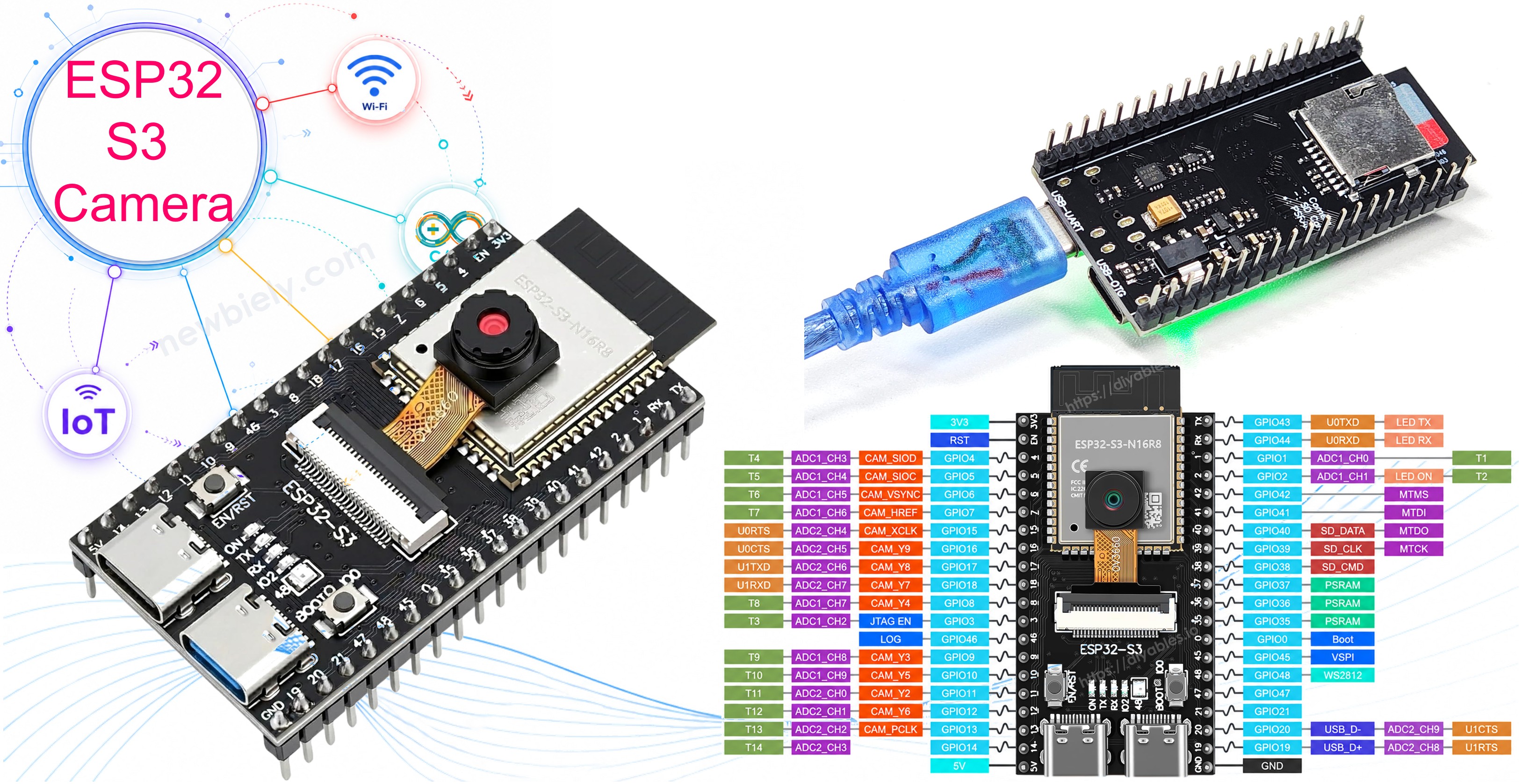
What you'll build:
- An ESP32 S3 camera board connected to your WiFi network
- Code that detects your camera sensor automatically (OV2640, OV3660 or OV5640)
- A small web server that shows live video in any web browser
- A second, shorter program that takes a big, sharp JPEG photo
Hardware Preparation
Or you can buy the following kits:
| 1 | × | DIYables Sensor Kit (18 sensors/displays) |
Additionally, some of these links are for products from our own brand, DIYables .
※ NOTE THAT:
The ESP32 S3 camera board has 40 pins, but the screw terminal block and the breakout board have 44 pins. They still work together. Put the camera board in the center of the 44-pin board, so 2 pins stay free on the left side and 2 pins stay free on the right side.
The screw terminal block lets you connect wires with a screwdriver, with no soldering. The breakout board gives you easy pin headers for a breadboard.
Overview of ESP32 S3 Camera
The ESP32 S3 camera board is an ESP32 S3 N16R8 board with a camera connector on it. The camera itself is a small module that plugs into this connector with a flat cable. The board has 16 MB of flash memory and 8 MB of PSRAM. The PSRAM is very important, because a photo is too big to fit in the normal memory of the chip.
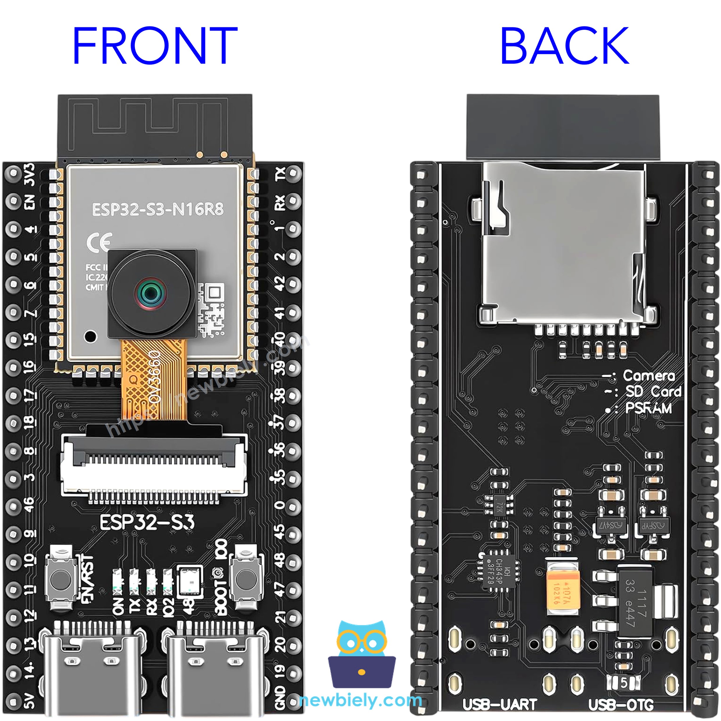
Key Specifications
| Item | Value |
|---|---|
| Microcontroller | ESP32 S3 (dual-core, 240 MHz) |
| Flash memory | 16 MB |
| PSRAM | 8 MB (OPI) |
| WiFi | 2.4 GHz, 802.11 b/g/n |
| Camera interface | DVP, 8-bit parallel |
| Image format | JPEG, RGB565, YUV422, Grayscale |
| Power | 5V from USB Type-C |
Camera Sensor Comparison
Three camera sensors are available for this board. They all use the same connector, the same pins, and the same code. They are different only in image size and image quality.
| Sensor | Resolution | Largest Image | Good For |
|---|---|---|---|
| OV2640 | 2 MP | UXGA 1600×1200 | Fast video, simple projects |
| OV3660 | 3 MP | QXGA 2048×1536 | Better detail, still fast |
| OV5640 | 5 MP | QSXGA 2592×1944 | Best photo quality |
※ NOTE THAT:
A bigger image is not always better. A bigger image takes more time to send over WiFi, so the video becomes slower. For live video, a small image such as SVGA (800×600) is usually the best choice, even if you have the OV5640.
How ESP32 S3 Camera Works
The camera sensor takes a picture and sends it to the ESP32 S3. This happens in three steps:
- The ESP32 S3 sends a clock signal to the camera on the XCLK pin. This clock makes the camera work.
- The ESP32 S3 sends settings to the camera on the SIOD and SIOC pins. These two pins are a control bus (similar to I2C).
- The camera sends the image data back on 8 data pins (D0 to D7), together with the PCLK, HREF and VSYNC pins. These three pins tell the ESP32 S3 where each pixel, each line, and each new image starts.
The camera can compress the image into the JPEG format by itself. This is important, because a JPEG image is about 10 times smaller than a raw image. A smaller image means faster video over WiFi.
The ESP32 S3 stores each image in the PSRAM. One stored image is called a frame buffer. Your code asks for a frame buffer, uses it, and then gives it back to the camera.
Image Size Names
The camera library uses short names for image sizes. You will see these names in the code:
| Name in code | Size in pixels | Works with |
|---|---|---|
| FRAMESIZE_QVGA | 320 × 240 | All sensors |
| FRAMESIZE_VGA | 640 × 480 | All sensors |
| FRAMESIZE_SVGA | 800 × 600 | All sensors |
| FRAMESIZE_HD | 1280 × 720 | All sensors |
| FRAMESIZE_UXGA | 1600 × 1200 | All sensors |
| FRAMESIZE_QXGA | 2048 × 1536 | OV3660 and OV5640 only |
| FRAMESIZE_QSXGA | 2592 × 1944 | OV5640 only |
Wiring Diagram between Camera and ESP32 S3
The camera connects to the ESP32 S3 board with a flat ribbon cable. You do not need a breadboard or any jumper wire.
- How to connect the camera module to the ESP32 S3 board
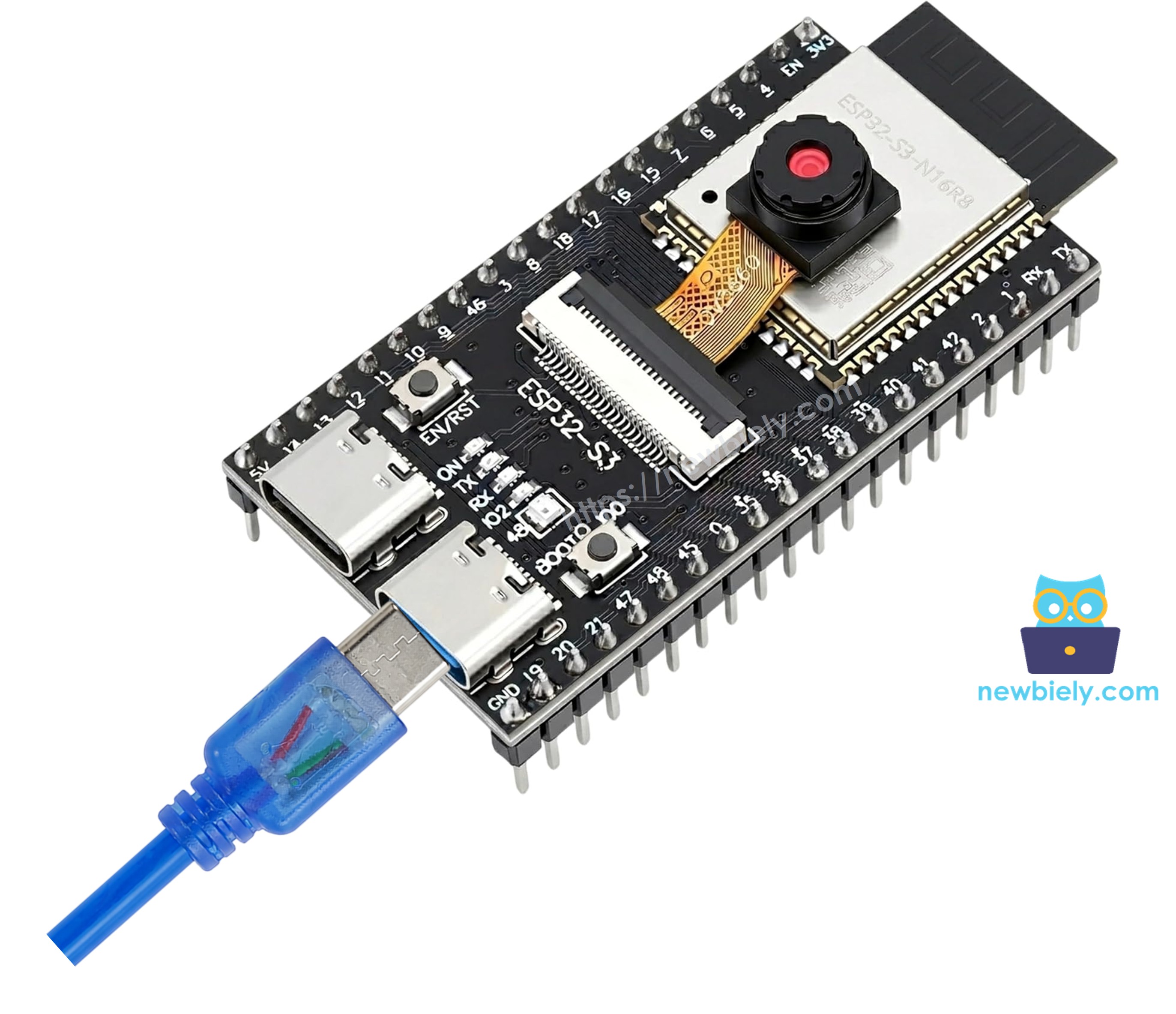
This image is created using Fritzing. Click to enlarge image
- Turn off the power. Unplug the USB cable first.
- Find the black connector on the board. Pull the small black bar up. Pull it gently.
- Push the flat cable into the connector. The blue side of the cable faces up, and the metal contacts face down.
- Push the small black bar down again to lock the cable.
- Plug in the USB cable.
Safety Notes
Never plug or unplug the camera while the board has power. This can damage the camera sensor. Always unplug the USB cable first. Also, do not pull the flat cable hard, because it breaks easily.
The table below shows how the camera is connected inside the board. You do not need to wire these pins yourself, but you need them in your code:
| Camera Pin | ESP32 S3 Pin | Meaning |
|---|---|---|
| XCLK | GPIO15 | Clock to the camera |
| SIOD | GPIO4 | Control data |
| SIOC | GPIO5 | Control clock |
| VSYNC | GPIO6 | Start of a new image |
| HREF | GPIO7 | Start of a new line |
| PCLK | GPIO13 | Pixel clock |
| D0 | GPIO11 | Data bit 0 |
| D1 | GPIO9 | Data bit 1 |
| D2 | GPIO8 | Data bit 2 |
| D3 | GPIO10 | Data bit 3 |
| D4 | GPIO12 | Data bit 4 |
| D5 | GPIO18 | Data bit 5 |
| D6 | GPIO17 | Data bit 6 |
| D7 | GPIO16 | Data bit 7 |
※ NOTE THAT:
These pins are used by the camera. Do not use them for other parts in your project.
Arduino IDE Settings for ESP32 S3 Camera
The camera does not work with the default settings of the Arduino IDE. You must change some items in the Tools menu before you upload the code.
| Tools Menu Item | Select This |
|---|---|
| Board | ESP32S3 Dev Module |
| Flash Size | 16MB (128Mb) |
| PSRAM | OPI PSRAM |
| Partition Scheme | Huge APP (3MB No OTA/1MB SPIFFS) |
| CPU Frequency | 240MHz (WiFi) |
| USB Mode | Hardware CDC and JTAG |
| Upload Mode | UART0 / Hardware CDC |
| Upload Speed | 921600 |
| USB CDC On Boot | Enabled |
※ NOTE THAT:
Two settings are the most important:
- PSRAM must be OPI PSRAM. If it is Disabled, the camera cannot start.
- Partition Scheme must be Huge APP. The camera code is big, and the default setting is too small for it.
Change Flash Size first, because the list of Partition Scheme options changes after that.
Install DIYables ESP32 WebServer Library
This tutorial uses the DIYables ESP32 WebServer library. This library makes the web server part very short and easy to read.
- Open the Arduino IDE.
- Click the Libraries icon on the left bar.
- Type DIYables ESP32 WebServer into the search box.
- Find the library by DIYables.io and click INSTALL.
- Search for DIYables ESP32 WebServer created by DIYables.io and click the Install button.
The camera library (esp_camera.h) is already inside the ESP32 board package. You do not need to install that one.
How To Program ESP32 S3 Camera
- Include the two libraries at the top of your code.
- Put your camera settings into a camera_config_t variable. The most important settings are the image format, the image size, and the image quality.
- Start the camera with the esp_camera_init() function. It returns ESP_OK when the camera starts correctly.
- Find out which camera sensor is on your board. Each sensor has its own ID number, called a PID.
- Take one photo with the esp_camera_fb_get() function. This function gives you a frame buffer. The photo is inside fb->buf, and its size in bytes is inside fb->len.
※ NOTE THAT:
You must call esp_camera_fb_return() after every esp_camera_fb_get(). If you forget it, the camera runs out of memory and stops after a few photos.
- Change how the image looks. For example, turn the image upside down or make it brighter.
※ NOTE THAT:
The OV3660 shows the image upside down by default. The code below fixes this with s->set_vflip(s, 1). If your own image is upside down or mirrored, change these two lines.
※ NOTE THAT:
The image size is different. Choose it one time in config.frame_size, before esp_camera_init(). Do not change it later while the code runs, or the camera will show the error cam_hal: FB-OVF and stop giving you images.
Now the web server part. The DIYables ESP32 WebServer library needs only three things: create the server, add your addresses, and call handleClient() again and again.
- Create the web server on port 80.
- Write one function for each address. Every function must have exactly these five parameters.
- Add your addresses inside setup() and start the server.
※ NOTE THAT:
Use server.begin() and connect to the WiFi yourself. Do not use server.begin(ssid, password) in this project, because that version sets the Serial Monitor speed to 9600, and then you cannot read the messages at 115200.
- To send live video, send many photos one after another, and put a separator text between them. This is called an MJPEG stream. Every web browser understands it. An image is not text, so you must use client.write() and not client.print().
- Call handleClient() inside loop(). Without this line, the web server does nothing.
※ NOTE THAT:
While one person watches the video, the ESP32 S3 is busy and cannot answer a second person. This is normal for a small board. Open the video on one device at a time.
ESP32 S3 Code - Example 1: Live Video
This is the simple example. It starts the camera, connects to your WiFi network, and shows the live video in a web browser. Start with this one.
The web server has two addresses:
- http://<IP>/ shows a web page with the live video
- http://<IP>/stream is the live video only
The code reads the sensor ID and sets the correct settings for the OV2640, the OV3660 or the OV5640 automatically. You do not need to change the code for your camera.
Detailed Instructions
- New to ESP32 S3? Complete our Getting Started with ESP32 S3 guide first.
- Connect the camera module to the board. Remember: unplug the USB cable first.
- Install the DIYables ESP32 WebServer library. See the steps above.
- Copy the above code and paste it into the Arduino IDE.
- Change YOUR_WIFI_SSID and YOUR_WIFI_PASSWORD to the name and the password of your WiFi network.
- Change the settings in the Tools menu. See the table above.
- Compile and upload the code to the ESP32 S3 board by clicking the Upload button in Arduino IDE.
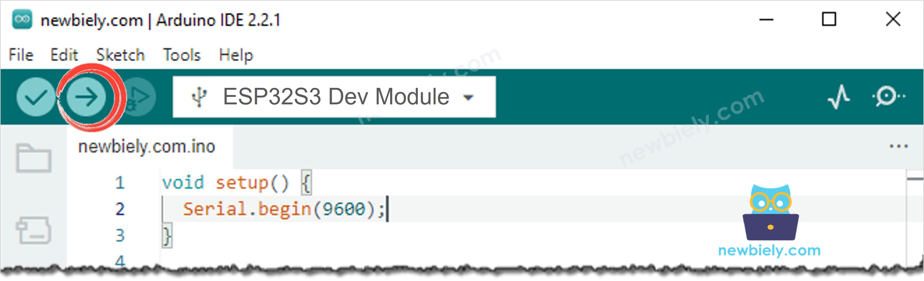
- Open the Serial Monitor in Arduino IDE.
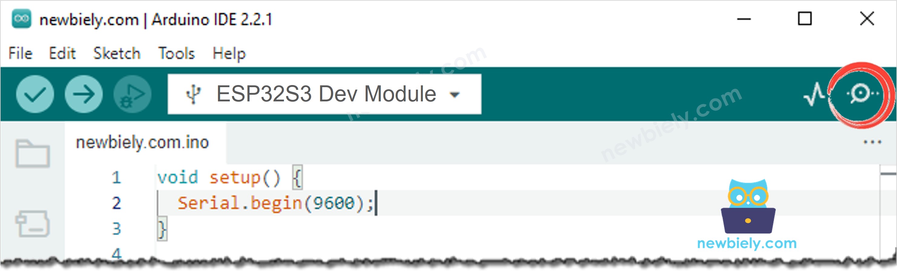
- Press the RESET button on the board one time.
- Read the IP address in the Serial Monitor.
- Type that address into your web browser and watch the live video.
- Pro Tip: Your computer or phone must be on the same WiFi network as the ESP32 S3. If they are on different networks, the page will not open.
Serial Monitor
After uploading, the Serial Monitor shows the name of your camera sensor and the IP address of the camera. The following readings were captured in 2026:
※ NOTE THAT:
The lines Method: GET, Requested path: / and Client disconnected come from the DIYables ESP32 WebServer library. They tell you that the web browser reached your board. This is normal.
The line with the sensor name is different for each camera:
| Your Camera | Line in the Serial Monitor |
|---|---|
| OV2640 | Camera sensor: OV2640 (2 MP, max UXGA 1600x1200) |
| OV3660 | Camera sensor: OV3660 (3 MP, max QXGA 2048x1536) |
| OV5640 | Camera sensor: OV5640 (5 MP, max QSXGA 2592x1944) |
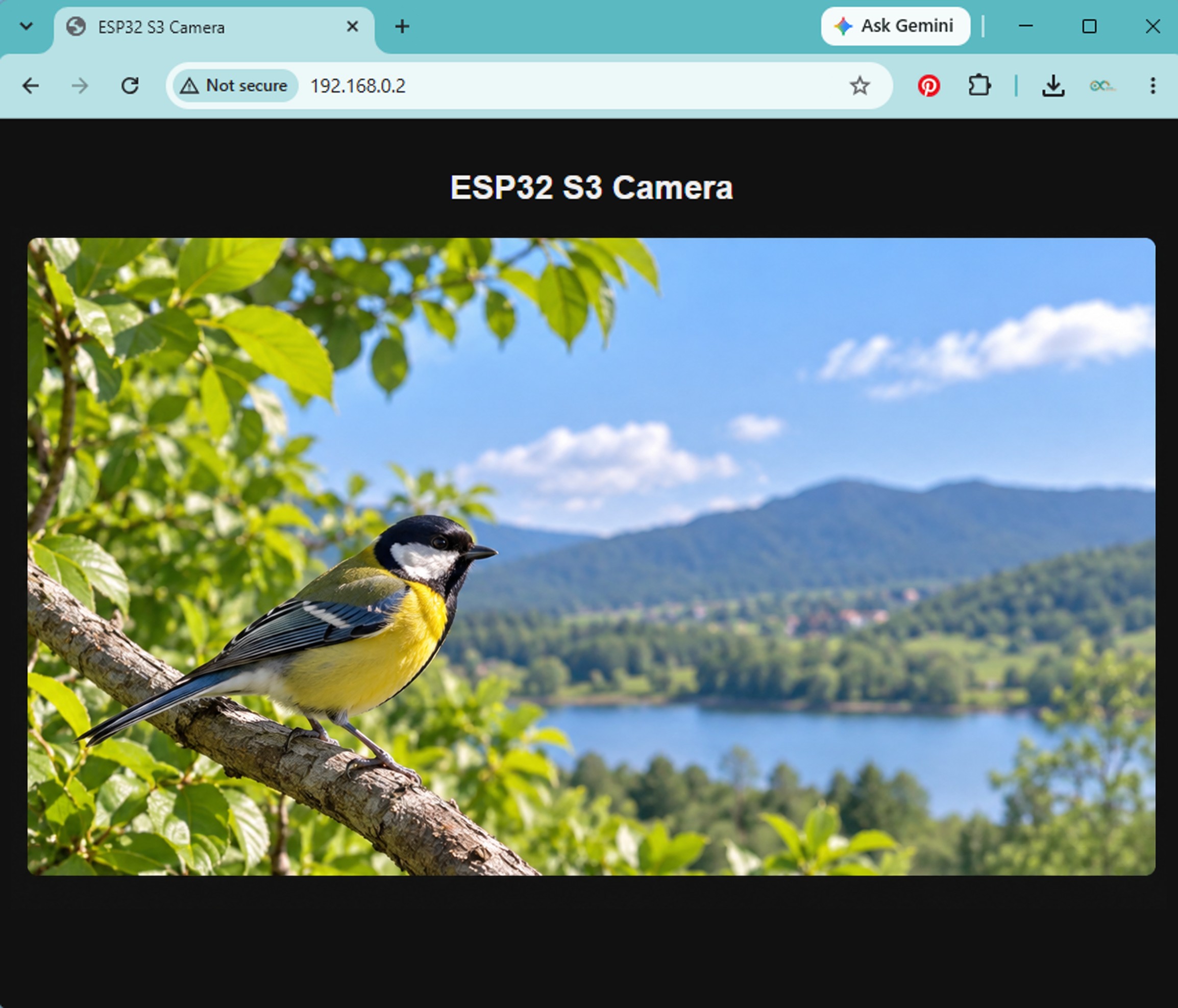
Now open the IP address in your web browser. You will see the live video from the camera:
ESP32 S3 Code - Example 2: Take a Photo
This example does not use video. It only takes a photo. The code is shorter and easier to read, so it is a good place to start if the video looks too difficult.
The web server has two addresses:
- http://<IP>/ shows the web page with the photo
- http://<IP>/photo is the photo only
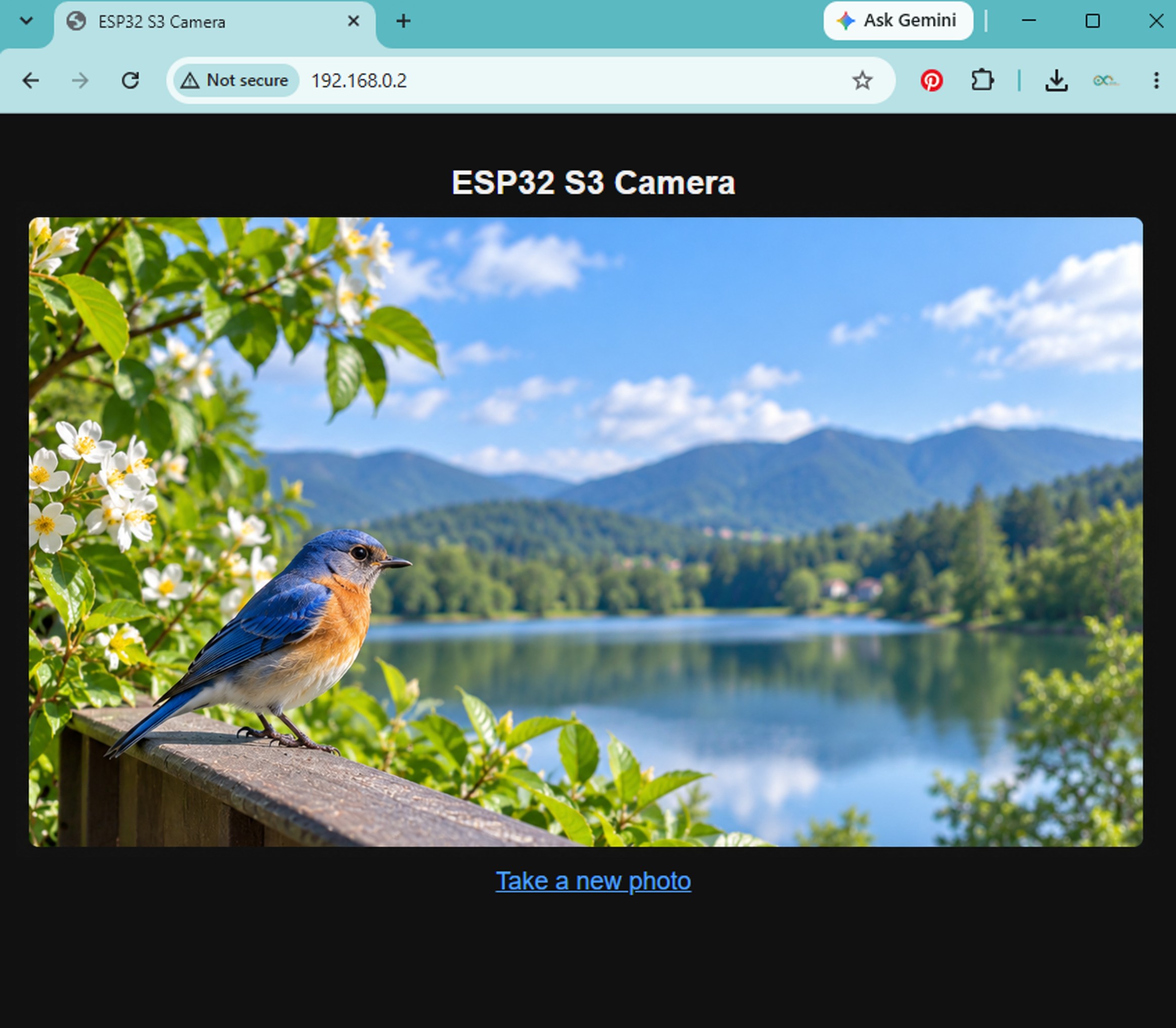
Every time the page opens, the ESP32 S3 takes a new photo. To take another photo, click the link Take a new photo.
How It Works
The web page has only two important lines:
The web browser reads <img src="/photo"> and asks the ESP32 S3 for the address /photo. The handlePhoto() function takes one photo and sends it back as a JPEG image. The link / opens the page again, so the camera takes a new photo. You do not need any JavaScript.
※ NOTE THAT:
This example uses a big image size (FRAMESIZE_UXGA, 1600×1200), because a photo does not need to be fast. Example 1 uses a small size (FRAMESIZE_SVGA, 800×600), because a small image travels faster over WiFi, and the video needs many images every second.
※ NOTE THAT:
Do you want an even bigger photo? Change config.frame_size to FRAMESIZE_QXGA (OV3660 and OV5640 only) or to FRAMESIZE_QSXGA (OV5640 only). A bigger photo needs more PSRAM and more time.
Detailed Instructions
- Copy the above code and paste it into the Arduino IDE.
- Change YOUR_WIFI_SSID and YOUR_WIFI_PASSWORD again.
- Upload the code and press the RESET button one time.
- Open the IP address in your web browser. The photo appears.
- Click Take a new photo to take another one.
- To keep a photo, right-click on the image and choose Save image as...
The Serial Monitor shows the size of each photo:
Troubleshooting
Here are the problems that beginners meet most often, and how to solve them.
The Serial Monitor shows nothing after the boot messages.
The USB CDC On Boot setting does not match your USB port. If your USB cable is in the port named UART, set USB CDC On Boot to Disabled. If your cable is in the port named USB, set it to Enabled. Then upload the code again. Also check that the speed box in the Serial Monitor shows 115200.
The Serial Monitor shows Camera init failed with error 0x105.
The camera cannot start. There are three common reasons:
- PSRAM is Disabled. Set it to OPI PSRAM in the Tools menu.
- The flat cable is loose or the wrong way round. Unplug the USB cable, open the connector, and put the cable in again.
- The clock is too fast for your camera module. Change config.xclk_freq_hz from 20000000 to 10000000 in the code.
The Serial Monitor shows WARNING: PSRAM not found.
Set PSRAM to OPI PSRAM in the Tools menu and upload the code again.
The upload fails, or the COM port does not appear.
Press and hold the BOOT button, press the RESET button one time, then release the BOOT button. Now the port appears in the Tools menu. After the upload finishes, press RESET one time.
The Serial Monitor shows the IP address, but the web page does not open.
Your computer and your ESP32 S3 are probably on different networks. Both must be on the same WiFi network. Also, type http:// and not https://, because the ESP32 S3 does not use https.
The video is slow, or it stops after a few seconds.
The image is too big for your WiFi. Change config.frame_size to a smaller size, such as FRAMESIZE_VGA or FRAMESIZE_QVGA. You can also increase config.jpeg_quality to 15, which makes a smaller file.
The Serial Monitor shows cam_hal: FB-OVF and Photo capture failed.
FB-OVF means "frame buffer overflow": the image is bigger than the memory that is ready for it. Choose your image size one time, inside config.frame_size, before you call esp_camera_init(). Do not change the size later with s->set_framesize(), because that function changes the camera sensor without making the memory bigger. If you really need to change the size while the code runs, use the esp_camera_reconfigure() function instead.
The photo takes a long time, or the page waits.
A big photo needs time. FRAMESIZE_UXGA takes about one second. Use FRAMESIZE_XGA or FRAMESIZE_SVGA if you want a faster photo.
The photo fails on every try.
Your image size is too big for the free memory. Use a smaller size, such as FRAMESIZE_XGA, or set config.fb_count to 1.
The image is upside down or mirrored.
Change the two lines s->set_vflip(s, 0) and s->set_hmirror(s, 0) in the code. Use 1 instead of 0.
Applications
An ESP32 S3 camera is small, cheap, and works over WiFi, so one board replaces an expensive IP camera. Here are practical projects you can build with this code:
- WiFi home security camera: Watch your door or your window from your phone, with no monthly payment.
- Pet camera for dogs and cats: See what your pet does when you are not at home.
- 3D printer monitor: Watch a long print job from another room, and stop it early when it goes wrong.
- Video doorbell: Take a photo when somebody presses the button at your door.
- Baby and child room camera: Look into the room from your phone without opening the door.
- Plant growth recorder: Take one photo every hour and join them into a time-lapse video.
- Robot car camera: Give eyes to a small robot, and drive it from another room.
- Drone and RC camera: Send live video from a model car, a boat, or a small drone.
- Aquarium and greenhouse watcher: Keep an eye on your fish or your plants while you travel.
- Machine and tutorial monitor: Watch a machine, a 3D printer farm, or a laser cutter while it runs.
- Shop and reception camera: Show the door of your shop on a screen at the back of the room.
- Learning project for students: A complete example of a camera, a web server and WiFi in one small board.
Video Tutorial
Watch the step-by-step video walkthrough for this ESP32 S3 project below.
Challenges
Now that you have a working camera on the ESP32 S3, try extending the project with these exercises to deepen your understanding.
- Beginner: Change the image size in the code from FRAMESIZE_SVGA to FRAMESIZE_VGA, then to FRAMESIZE_UXGA. Watch how the speed of the video changes.
- Intermediate: Add a button to the board. When somebody presses the button, take one photo and save it to the SD card.
- Advanced: Take one photo every 10 minutes and send it to your phone with a Telegram bot, so you get a picture even when you are far from home.