
ESP32 S3 - Flame Sensor
Learn how to build a fire detection system using an ESP32 S3 and a flame sensor to monitor and detect flames for safety applications. This beginner-friendly tutorial covers everything you need to get started with infrared flame sensors.
What you'll build:
- A digital flame detector that reports fire presence to the Serial Monitor
- An analog flame intensity reader that measures fire strength in real time
- A foundation for building automated fire alarm and suppression systems
- A practical sensor integration project on the ESP32 S3 platform
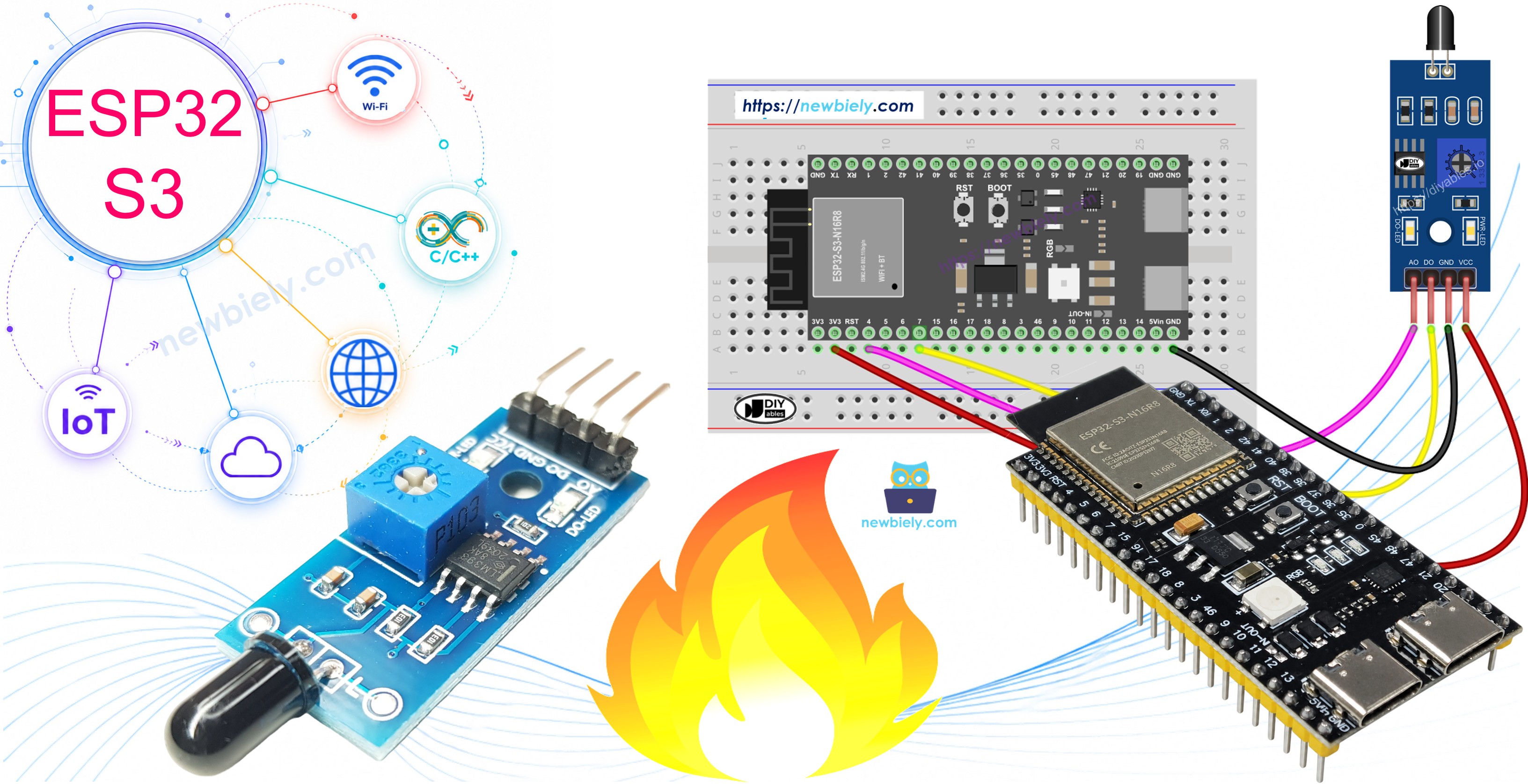
Hardware Preparation
Or you can buy the following kits:
| 1 | × | DIYables ESP32 S3 Starter Kit (ESP32 S3 included) | |
| 1 | × | DIYables Sensor Kit (18 sensors/displays) |
Additionally, some of these links are for products from our own brand, DIYables .
Overview of Flame Sensor
A flame sensor is an infrared detector that senses flame presence and measures fire intensity through infrared light detection. It provides both a simple digital on/off signal and a continuous analog voltage proportional to the strength of the detected infrared radiation. The module's onboard potentiometer lets you fine-tune sensitivity to suit your environment.
Key Specifications
- Detects infrared radiation from flames (760nm to 1100nm wavelength)
- Provides both digital (on/off) and analog (intensity) outputs
- Adjustable sensitivity via onboard potentiometer
- Works with 3.3V to 5V power supply
- Fast response time for quick fire detection
- Built-in LED indicators for power and flame status
- Detection range typically 60–80 cm (varies by model)
Why It's Useful for Beginners:
- Simple two or three-wire connection to ESP32 S3
- Easy to understand digital output for basic fire detection
- No complex programming required
- Affordable and widely available
- Great for learning about sensor integration
Important Limitations:
- May produce false positives from sunlight or heat sources
- Requires proper positioning and sensitivity adjustment
- Should not be sole fire safety device in critical applications
Pinout
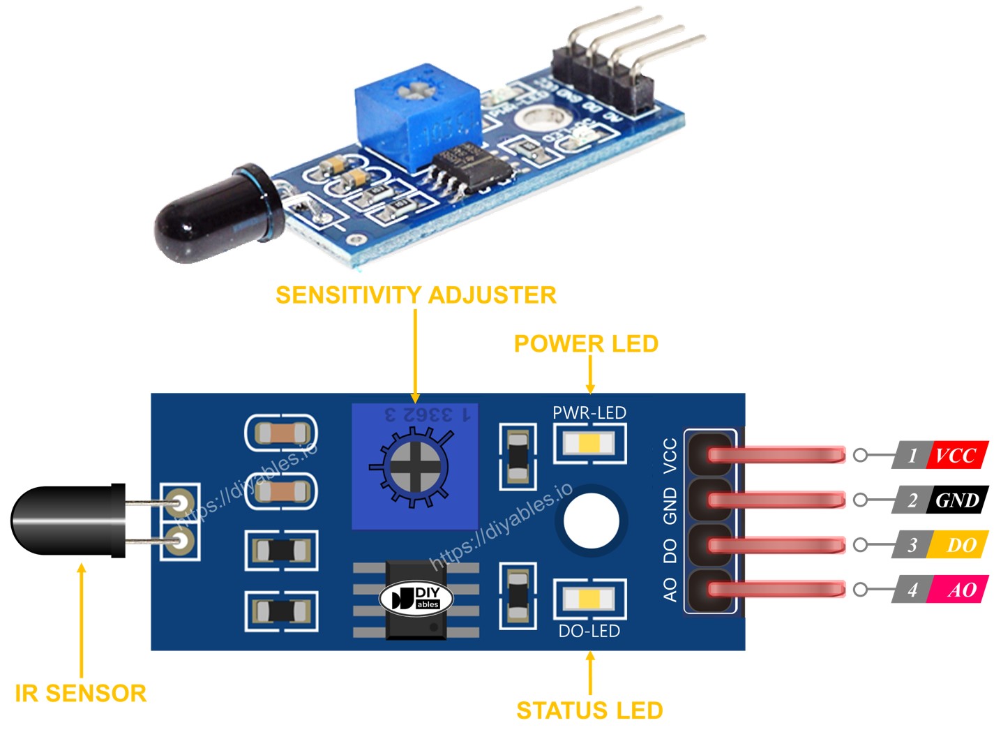
The flame sensor module provides four pins that give you both digital and analog access to its readings.
- VCC: Power supply input (3.3V to 5V)
- GND: Ground connection (0V)
- DO: Digital output pin — LOW when flame detected, HIGH when no flame
- AO: Analog output pin — voltage varies with infrared intensity level
LED Indicators:
- PWR-LED: Power indicator — lights when module is powered
- DO-LED: Flame detection indicator — lights when flame is detected
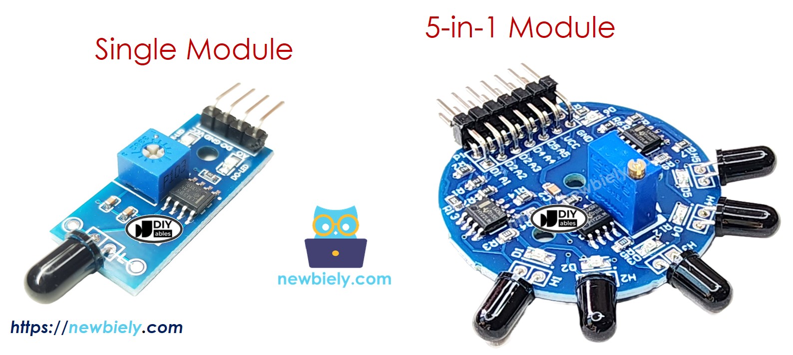
5-in-1 Flame Sensor Module:
- Features five independent flame sensors on one board
- Each sensor has separate DO and AO pins
- Sensors point in different directions for 360° coverage
- Shares common VCC, GND, and potentiometer
- Provides wider detection area than single sensor
How It Works
The infrared flame sensor detects specific wavelengths of infrared light emitted by flames.
Digital Output (DO Pin):
- Adjust sensitivity by turning the onboard potentiometer
- When infrared intensity exceeds threshold: DO pin goes LOW, LED turns on
- When infrared intensity is below threshold: DO pin stays HIGH, LED turns off
- Use for simple yes/no flame detection
- Perfect for triggering alarms or automated systems
Analog Output (AO Pin):
- Output voltage increases with higher infrared intensity
- Output voltage decreases with lower infrared intensity
- Provides continuous measurement of flame strength
- Useful for distance estimation or flame size monitoring
- Not affected by potentiometer adjustment
Detection Process:
- Sensor continuously monitors infrared radiation
- Built-in comparator converts analog signal to digital output
- Both outputs available simultaneously for flexible applications
Wiring Diagram
Connect the flame sensor to your ESP32 S3 based on whether you need digital detection, analog measurement, or both. Ensure all connections are secure before powering the board.
Safety Notes
Always test with actual flame sources in a safe, controlled environment away from flammable materials. Do not rely solely on this sensor for critical fire safety applications, and keep the sensor away from direct sunlight during testing to avoid false readings.
| Flame Sensor Pin | ESP32 S3 Pin |
|---|---|
| VCC | 3.3V |
| GND | GND |
| DO | GPIO6 |
| AO | A5 (GPIO5 / ADC1_CH5) |
Wiring Diagram - Both Digital and Analog:
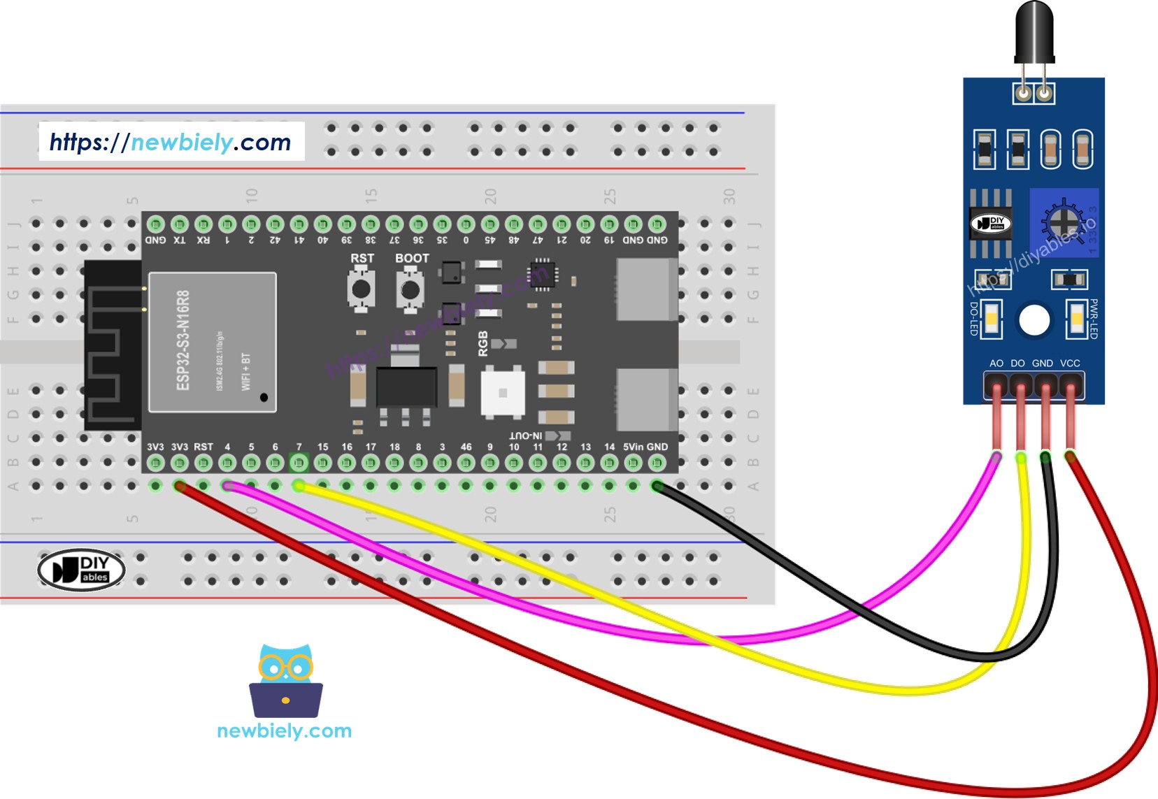
This image is created using Fritzing. Click to enlarge image
ESP32 S3 Code - Read value from DO pin
The following code reads the digital output from the flame sensor to detect fire presence. It configures GPIO6 as a digital input, polls the pin every 500 milliseconds, and prints a human-readable fire detection status to the Serial Monitor so you can observe the sensor's response in real time.
Detailed Instructions
- New to ESP32 S3? Complete our Getting Started with ESP32 S3 guide first.
- Open Arduino IDE: Launch the Arduino IDE on your computer.
- Copy the code: Copy the code above and paste it into Arduino IDE.
- Select your board: Go to Tools > Board > ESP32S3 Dev Module.
- Select your port: Go to Tools > Port and select the correct COM port.
- Upload the code: Click the Upload button to program your ESP32 S3.
- Test the sensor: Point the flame sensor at a candle or lighter flame.
- Open Serial Monitor: Click the Serial Monitor icon (top right) and set baud rate to 115200.
- View results: Watch the flame detection status change in real-time.
- Adjust sensitivity: Turn the potentiometer if the sensor is too sensitive or not sensitive enough.
- Pro Tip: If the DO-LED stays on or off constantly, adjust the onboard potentiometer clockwise or counterclockwise until the LED responds correctly to flame presence.
Serial Monitor Output
ESP32 S3 Code - Read value from AO pin
The following code reads the analog output from the flame sensor to measure flame intensity. It configures GPIO5 as an analog input, samples the ADC continuously, and displays the raw 12-bit value (0–4095) in the Serial Monitor — higher values indicate a stronger flame or closer proximity to the sensor.
Detailed Instructions
- New to ESP32 S3? Complete our Getting Started with ESP32 S3 guide first.
- Open Arduino IDE: Launch the Arduino IDE on your computer.
- Copy the code: Copy the code above and paste it into Arduino IDE.
- Select your board: Go to Tools > Board > ESP32S3 Dev Module.
- Select your port: Go to Tools > Port and select the correct COM port.
- Upload the code: Click the Upload button to program your ESP32 S3.
- Test the sensor: Point the flame sensor toward a flame source.
- Open Serial Monitor: Click the Serial Monitor icon and set baud rate to 115200.
- Observe readings: Watch how values increase as you move the flame closer.
- Test distance: Move the flame farther away and see values decrease.
- Pro Tip: Record baseline values in your environment without flames, then use those values to set detection thresholds in your code for automatic fire alarms.
Serial Monitor Output
※ NOTE THAT:
This tutorial uses the analogRead() function to read values from an ADC (Analog-to-Digital Converter) connected to a sensor or component. The ESP32 S3's ADC is suitable for projects that do not require high accuracy. However, for projects needing precise measurements, keep the following in mind:
- The ESP32 S3's ADC is not perfectly accurate and might require calibration for correct results. Each ESP32 S3 board can vary slightly, so calibration is necessary for each individual board.
- Calibration can be challenging, especially for beginners, and might not always yield the exact results you want.
For projects requiring high precision, consider using an external ADC (e.g ADS1115) with the ESP32 S3 or using another Arduino, such as the Arduino Uno R4 WiFi, which has a more reliable ADC. If you still want to calibrate the ESP32 S3's ADC, refer to the ESP32 ADC Calibration Driver.
Application Ideas
The ESP32 S3's processing power and wireless connectivity make it an excellent platform for a wide range of flame-sensing applications.
- Smart fire alarm system: Add a buzzer and LED warnings for real-time home safety alerts.
- Automatic fire extinguisher trigger: Activate a relay-controlled suppression system in small enclosed spaces.
- Fire-fighting robot: Build a robot that navigates toward flames and activates a suppression mechanism.
- Industrial furnace monitor: Track flame presence in heating equipment to prevent unsafe shutoffs.
- Gas stove safety system: Detect if a flame goes out unexpectedly and alert the user immediately.
- Multi-zone fire detection: Deploy multiple sensors across a large area for comprehensive coverage.
- IoT fire alert system: Leverage the ESP32 S3's WiFi to send push notifications to your smartphone.
Video Tutorial
Watch the step-by-step video walkthrough for this ESP32 S3 project below.
Challenge Yourself
These challenges will help you go beyond the basics and build more capable flame-detection systems with your ESP32 S3.
- Beginner: Add a buzzer that sounds when flame is detected using the digital output.
- Beginner: Add an LED that lights up when flame intensity exceeds a threshold value.
- Intermediate: Create a flame intensity meter using multiple LEDs as a bar graph display.
- Intermediate: Combine digital and analog readings to build a smart fire alarm with distance warning.
- Advanced: Build a WiFi-enabled fire monitoring system that sends alerts to your smartphone.
- Advanced: Create a multi-sensor fire detection array using the 5-in-1 module for 360° coverage.