
ESP32 S3 - Door Sensor
Learn how to detect door and window states with your ESP32 S3 and a magnetic door sensor. This beginner-friendly tutorial walks you through everything you need to monitor open and close events reliably using the ESP32 S3 board.
What you'll build:
- A circuit connecting the magnetic door sensor to the ESP32 S3
- Arduino code that reads the sensor state and detects door-open and door-closed conditions
- Arduino code that detects door-opening and door-closing transition events
- Serial Monitor output showing real-time door state results
Hardware Preparation
Or you can buy the following kits:
| 1 | × | DIYables ESP32 S3 Starter Kit (ESP32 S3 included) | |
| 1 | × | DIYables Sensor Kit (18 sensors/displays) |
Additionally, some of these links are for products from our own brand, DIYables .
Overview of Door Sensor
The door sensor (also known as entry sensor, contact sensor, or window sensor) is widely used in security and automation applications to detect whether an entrance such as a door or window is open or closed. It consists of two separate components — a magnet and a reed switch — that work together to provide a simple and reliable digital signal to the ESP32 S3.
Key Specifications
The door sensor is a passive, two-wire device that requires no external power supply of its own. The reed switch is a normally open or normally closed magnetic switch that changes state when the accompanying magnet is brought close. Because the sensor behaves electrically just like a button or switch, the ESP32 S3 internal pull-up resistor is all that is needed to read it reliably on any digital input pin.
Door Sensor Pinout
The door sensor has two components that must be installed together for correct operation.
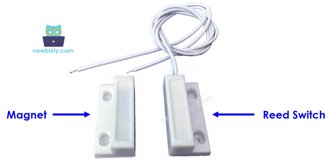
- Magnet: The movable part — attach this to the door or window itself
- Reed Switch (two wires): The fixed part — attach this to the door frame; connect one wire to GND and the other to an ESP32 S3 input pin with a pull-up resistor
How Door Sensor Works
The magnet and the reed switch are installed on the door or window frame as a matched pair. The magnet is attached to the moving part (the door), while the reed switch is fixed to the frame — the two components must be in close proximity when the door is closed.
When the magnet is near the reed switch, the switch's internal contacts close, forming a complete circuit. When the door opens and the magnet moves away, the contacts open again, breaking the circuit. By connecting one wire of the reed switch to GND and the other to an ESP32 S3 input pin configured with a pull-up resistor, the pin reads LOW when the door is closed and HIGH when it is open.
※ NOTE THAT:
Just like a button, you MUST use a pull-up or pull-down resistor on the ESP32 S3 pin connected to the reed switch to avoid a floating input state.
So:
- If the ESP32 S3's input pin is LOW, the door is closed
- If the ESP32 S3's input pin is HIGH, the door is opened
- If the ESP32 S3's input pin changes from LOW to HIGH, the door is opening
- If the ESP32 S3's input pin changes from HIGH to LOW, the door is closing
Wiring Diagram
Connect the door sensor reed switch to the ESP32 S3 as shown in the diagram below. One wire of the reed switch goes to GND and the other connects to an ESP32 S3 digital input pin, which uses the board's internal pull-up resistor to maintain a defined logic level when the switch is open.
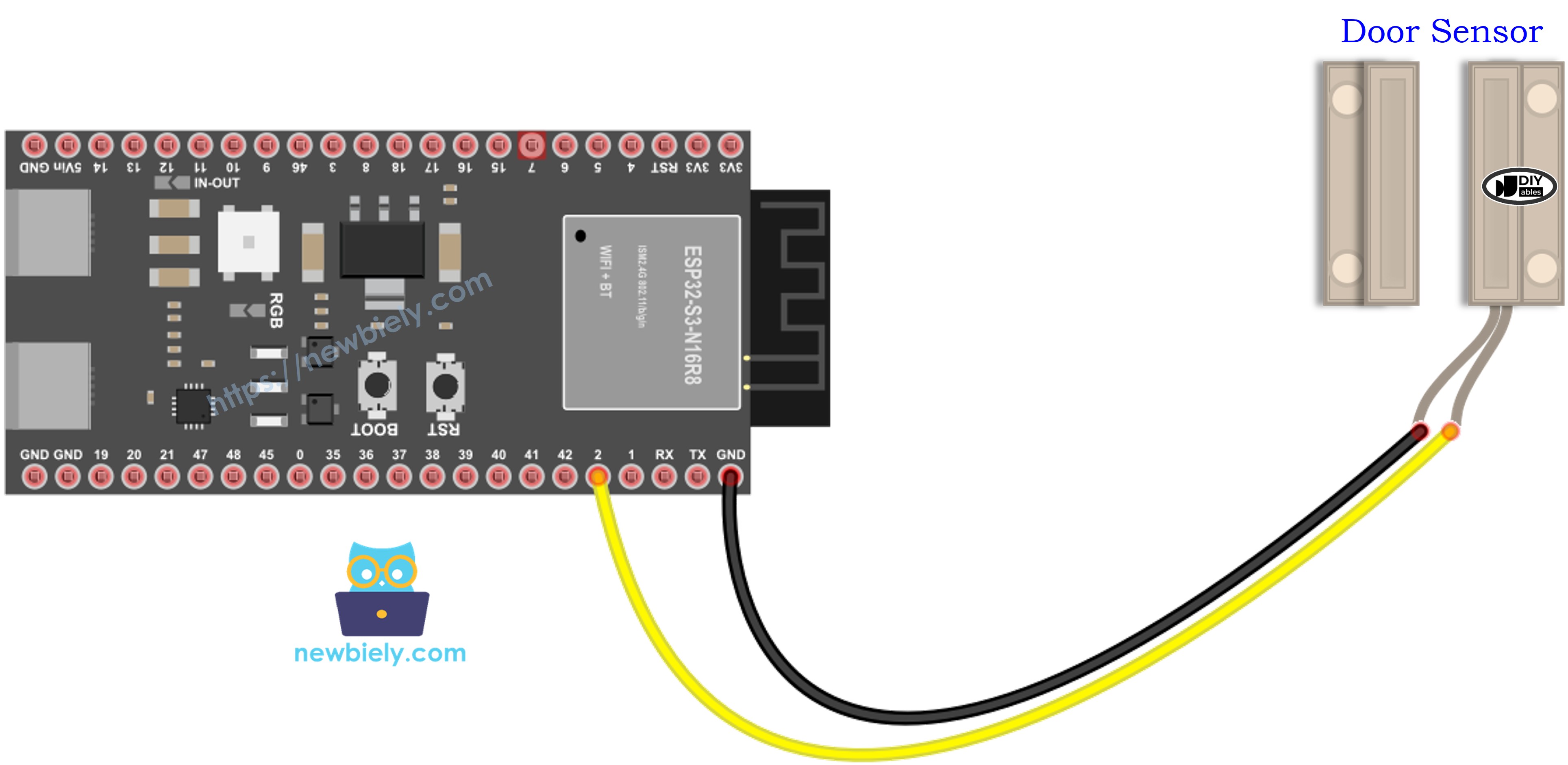
This image is created using Fritzing. Click to enlarge image
Safety Notes
The reed switch is a low-voltage, low-current passive device that is safe to connect directly to the ESP32 S3's GPIO pins. Always enable the internal pull-up resistor (INPUT_PULLUP) to prevent a floating input when the switch is open; without it you will see erratic and unreliable readings. Keep the sensor wires away from high-current lines to avoid induced electrical noise that could cause false triggers.
| Door Sensor Pin | ESP32 S3 Pin |
|---|---|
| Wire 1 (reed switch) | GND |
| Wire 2 (reed switch) | GPIO2 |
How To Program Door Sensor
Programming the ESP32 S3 to read the door sensor mirrors the approach used for a button or switch. The key steps are to initialize the pin with the internal pull-up resistor and then read the digital state on every loop iteration.
Step 1: Initialize the ESP32 S3 Pin
Step 2: Read the Door State
ESP32 S3 Code - Check Door Open and Close State
The following code continuously reads the reed switch on GPIO2 and prints the current door state — open or closed — to the Serial Monitor on every loop cycle. It configures the pin with the internal pull-up resistor so no external components are needed beyond the sensor wires.
Detailed Instructions
- New to ESP32 S3? Complete our Getting Started with ESP32 S3 guide first.
- Follow the wiring diagram above to connect the door sensor reed switch to the ESP32 S3.
- Connect your ESP32 S3 to your computer via USB Type-C.
- Copy the code above and paste it into the Arduino IDE.
- Select your ESP32 S3 board from the Tools > Board menu.
- Click the Upload button in the Arduino IDE to transfer the code.
- Open the Serial Monitor by clicking its icon or pressing Ctrl+Shift+M.
- Set the baud rate to 115200 in the Serial Monitor dropdown.
- Move the magnet close to the reed switch, then move it away, and observe the output.
- Pro Tip: Use INPUT_PULLUP instead of INPUT to avoid adding an external pull-up resistor — the ESP32 S3's built-in pull-up handles it for you.
Serial Monitor Output
When you move the magnet toward and away from the reed switch, you will see output similar to the following:
ESP32 S3 Code - Detect Door-opening and Door-closing Events
The following code tracks the previous and current state of the reed switch to detect the exact moment the door transitions from closed to open (a door-opening event) or from open to closed (a door-closing event). Only a single message is printed per event, making it ideal for triggering actions like alarms or logs.
Detailed Instructions
- New to ESP32 S3? Complete our Getting Started with ESP32 S3 guide first.
- Follow the wiring diagram above to connect the door sensor reed switch to the ESP32 S3.
- Connect your ESP32 S3 to your computer via USB Type-C.
- Copy the code above and paste it into the Arduino IDE.
- Select your ESP32 S3 board from the Tools > Board menu.
- Click the Upload button in the Arduino IDE to transfer the code.
- Open the Serial Monitor and set the baud rate to 115200.
- Move the magnet close to the reed switch and then move it away to trigger both events.
- Pro Tip: Use the door-opening event to start a timer and the door-closing event to stop it — this lets you calculate how long the door was open in each session.
Serial Monitor Output
When door transitions occur, you will see output similar to the following:
Applications
The door sensor paired with the ESP32 S3 enables a wide range of practical security and automation projects, from simple alerts to integrated smart-home systems.
- Home Security Alert: Trigger a buzzer or send a push notification whenever a door or window is opened unexpectedly.
- Smart Doorbell: Detect when a door is opened and announce an entry event on a connected speaker or display.
- Energy Efficiency Monitor: Track how often and for how long refrigerator or cabinet doors are left open to reduce wasted energy.
- Access Control Log: Record timestamps of door-opening and door-closing events to an SD card or cloud server for audit trails.
- Child Safety Guard: Alert parents when a prohibited door (such as a garage or outdoor gate) is opened.
- Automated Lighting: Turn on a room light when a door opens and turn it off after the door has been closed for a set time.
Video Tutorial
Watch the step-by-step video walkthrough for this ESP32 S3 project below.
Challenge Yourself
Once your door sensor is working, try these challenges to deepen your ESP32 S3 skills — starting with simple additions and progressing to more advanced connected features.
- Beginner: Add an LED that lights up whenever the door is open and turns off when it is closed.
- Beginner: Count and display on the Serial Monitor the total number of times the door has been opened since the board was powered on.
- Intermediate: Add a buzzer that sounds for 2 seconds each time a door-opening event is detected.
- Intermediate: Display the current door state (OPEN / CLOSED) on an OLED or LCD screen in real time.
- Advanced: Build a door-open timer that measures how many seconds the door stays open each time and logs the longest session to the Serial Monitor.
- Advanced: Create a Wi-Fi-connected alert system that sends an HTTP request to a home automation server whenever the door state changes.