
ESP32 S3 - Keypad 1x4
This guide walks you through connecting and programming a 1x4 keypad with an ESP32 S3. You will learn how each key maps to a GPIO pin and how to use the ezButton library to cleanly handle debouncing without disrupting other parts of your sketch.
What you'll build:
- A 1x4 keypad circuit wired to the ESP32 S3 using jumper wires.
- Code that detects which key is pressed and prints its label to the Serial Monitor.
- A debounced keypad reader that eliminates false multiple-press readings.
- A foundation you can extend for password entry, menu navigation, or device control.
Hardware Preparation
Or you can buy the following kits:
| 1 | × | DIYables ESP32 S3 Starter Kit (ESP32 S3 included) | |
| 1 | × | DIYables Sensor Kit (18 sensors/displays) |
Additionally, some of these links are for products from our own brand, DIYables .
Overview of Keypad 1x4
A 1x4 keypad contains four membrane buttons arranged in a single row, making it a compact input device for embedded projects. It is commonly used to let users enter data such as passwords, navigate simple menus, or trigger device actions without a full keyboard.
Key Specifications
The 1x4 keypad connects through five pins and operates at 3.3 V logic levels, which matches the ESP32 S3's GPIO voltage perfectly. Each key acts as a momentary switch between its dedicated pin and the common pin, so no external pull-up or pull-down resistor is required when using the microcontroller's internal pull-up resistors.
Pinout
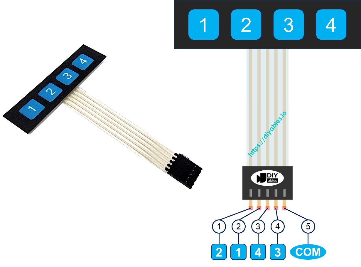
The 1x4 keypad exposes five pins whose order does not match the key labels printed on the membrane.
- Pin 1: links with key 2
- Pin 2: links with key 1
- Pin 3: links with key 4
- Pin 4: links with key 3
- Pin 5: connects to all keys and is the common pin
Wiring Diagram
Connect each of the four key pins on the keypad to a dedicated GPIO pin on the ESP32 S3, and wire the common pin (Pin 5) to GND. The ESP32 S3's internal pull-up resistors will hold each GPIO HIGH until a key is pressed.
Safety Notes
Always connect the keypad's common pin to GND and enable internal pull-up resistors in code so the GPIO pins are never left floating. Avoid routing the keypad wires near high-current traces or relay coils, as electrical noise can cause false key readings.
| Keypad 1x4 | ESP32 S3 |
|:---|:---|
| Pin 1 (key 2) | GPIO5 |
| Pin 2 (key 1) | GPIO4 |
| Pin 3 (key 4) | GPIO7 |
| Pin 4 (key 3) | GPIO6 |
| Pin 5 (common) | GND |
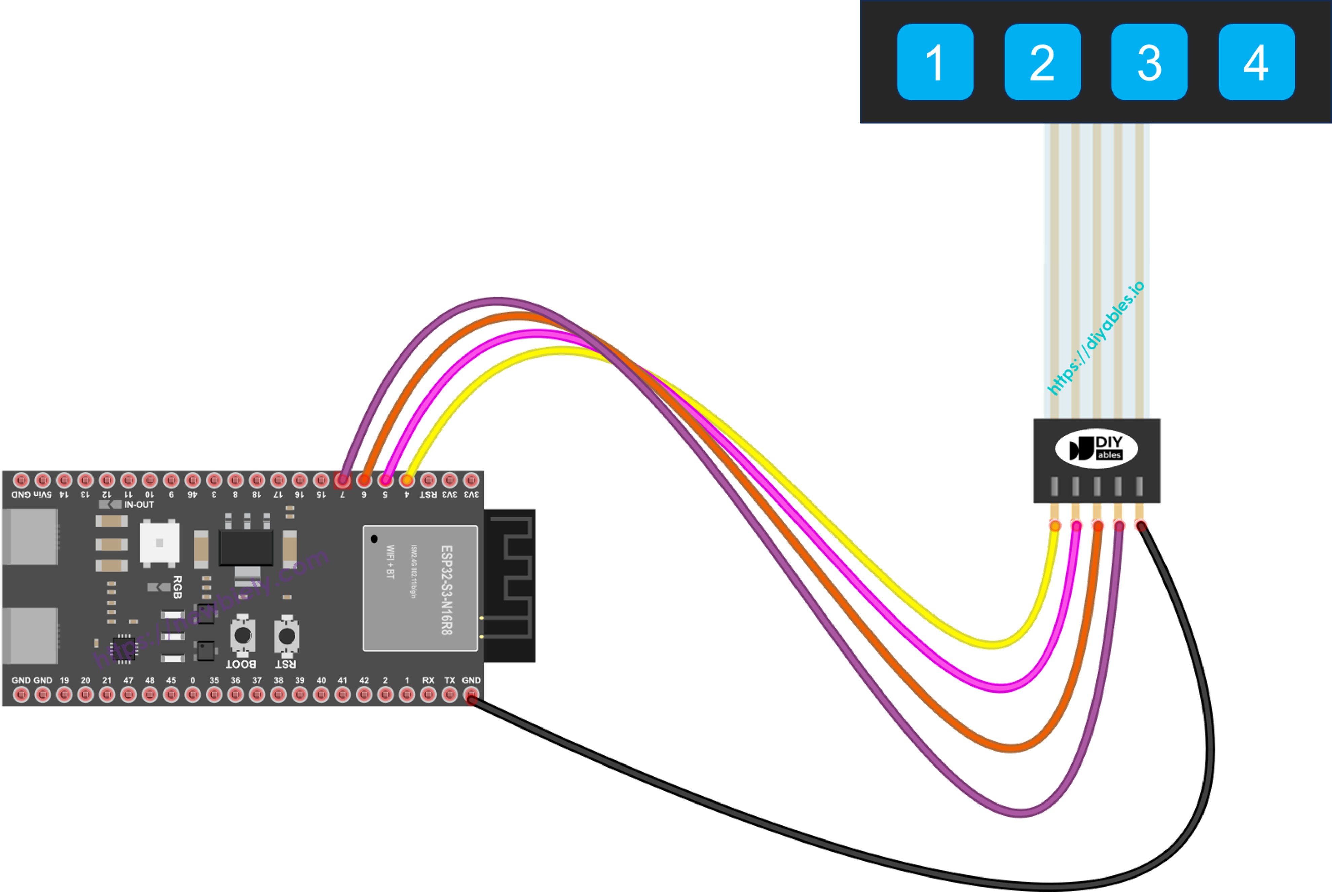
This image is created using Fritzing. Click to enlarge image
ESP32 S3 Code
Each key on the 1x4 keypad behaves like a momentary button, so the ESP32 S3 reads it with digitalRead(). However, physical keys exhibit contact bounce that can cause a single press to register as multiple events, so debouncing is essential. The following code uses the ezButton library to handle debounce for all four keys automatically, making the sketch clean and easy to extend.
Detailed Instructions
- New to ESP32 S3? Complete our Getting Started with ESP32 S3 guide first.
- Wire the keypad to the ESP32 S3 as shown in the wiring diagram above.
- Connect the ESP32 S3 board to your PC via a USB Type-C cable.
- Open Arduino IDE on your PC.
- Select the right ESP32 S3 board (e.g. ESP32S3 Dev Module) and the correct COM port.
- Click the Libraries icon on the left bar of the Arduino IDE.
- Search "ezButton", then find the button library by ArduinoGetStarted.com.
- Click Install button to install the ezButton library.
- Search for ezButton created by ArduinoGetStarted.com and click the Install button.
- Copy the above code and paste it into Arduino IDE.
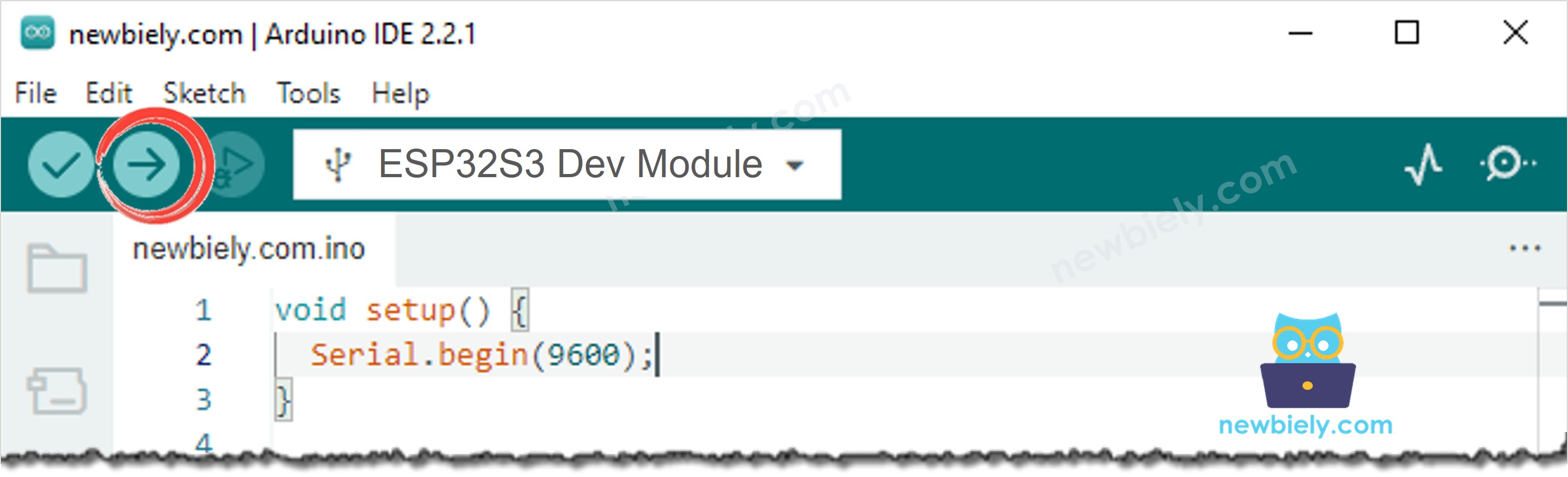
- Click the Upload button in Arduino IDE to upload the code to the ESP32 S3.
- Open Serial Monitor on Arduino IDE.
- Press each key on the 1x4 keypad and check the output in Serial Monitor.
Pro Tip: If a key registers multiple presses with a single press, increase the debounce interval in the ezButton settings to filter out mechanical bounce from your specific keypad membrane.
Serial Monitor Output
Open the Serial Monitor at 9600 baud to observe which keys the ESP32 S3 detects as you press them. The following readings show a typical session with timestamps:
Applications
The 1x4 keypad gives the ESP32 S3 a simple but versatile input interface suitable for a wide range of embedded projects. Here are some common applications:
- Password Entry: Use four keys to enter a numeric PIN that unlocks a relay-controlled door lock or safe.
- Menu Navigation: Assign keys to up, down, select, and back actions for navigating an OLED display menu.
- Device Mode Selector: Switch between operational modes such as manual, automatic, timer, and off with a single keypress.
- Alarm Control: Arm and disarm a motion-sensor alarm system by pressing a designated key combination.
- Score Tracker: Increment or decrement a score counter displayed on an LCD screen during a tabletop game.
Video Tutorial
Watch the step-by-step video walkthrough for this ESP32 S3 project below.
Challenges
Experimenting beyond the basic keypad reader is the best way to deepen your understanding of input handling on the ESP32 S3. Try these challenges to build confidence with more advanced techniques:
- Beginner: Modify the code so each key toggles a different LED connected to a GPIO pin on the ESP32 S3.
- Intermediate: Implement a 4-digit PIN system that unlocks a relay when the correct sequence is entered and prints "Access Granted" or "Access Denied" to the Serial Monitor.
- Advanced: Combine the 1x4 keypad with an OLED display to build a fully navigable menu that lets the user select and adjust device settings without a computer.