
ESP32 S3 - Sound Sensor
Sound sensors detect the presence of sound and enable your ESP32 S3 to create interactive, sound-responsive projects like clap-activated lights or voice-triggered devices. This tutorial will show you how to connect and program a sound sensor with your ESP32 S3 board.
What you'll build:
- A sound detection circuit with ESP32 S3 and a digital or analog sound sensor
- Arduino code that reads the sensor state and identifies sound events
- Serial Monitor output that reports when sound is detected or disappears
- A foundation you can extend to trigger LEDs, relays, or servo motors on sound
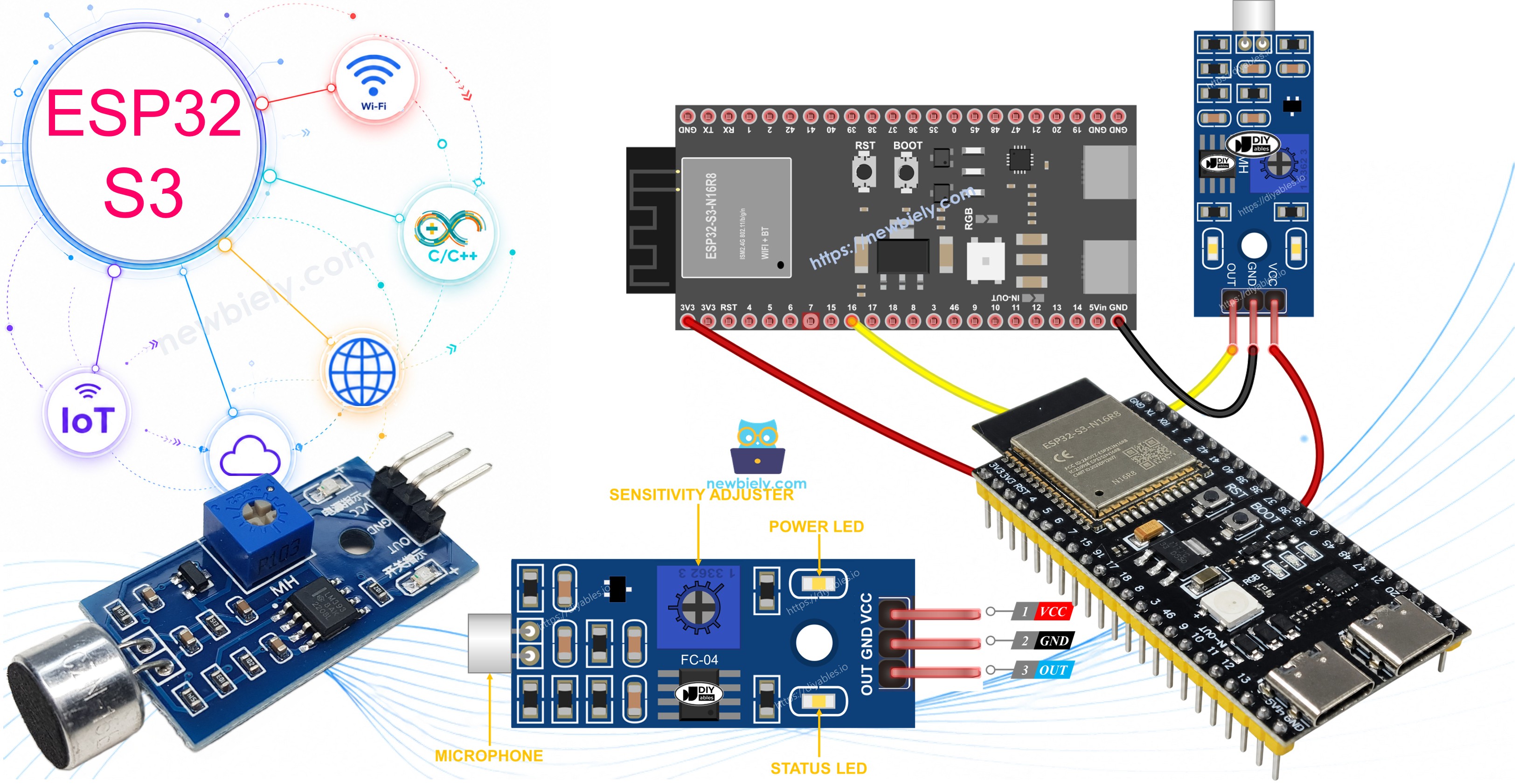
After completing this tutorial, you can modify the code to trigger actions when sound is detected - turn on an LED, activate a relay to control lights, or rotate a servo motor based on sound input.
Hardware Preparation
Or you can buy the following kits:
| 1 | × | DIYables ESP32 S3 Starter Kit (ESP32 S3 included) | |
| 1 | × | DIYables Sensor Kit (18 sensors/displays) |
Additionally, some of these links are for products from our own brand, DIYables .
Overview of Sound Sensor
A sound sensor is a detection module that senses sound waves in the surrounding environment and converts them to electrical signals. It uses a microphone element and onboard circuitry to produce both digital and analog outputs that microcontrollers like the ESP32 S3 can read directly. The module's built-in potentiometer lets you fine-tune the detection threshold so the sensor responds to exactly the sound level your project requires.
Key Specifications
- Output types: Digital (HIGH/LOW) and analog (voltage proportional to sound level)
- Operating voltage: 3.3V to 5V — compatible with the ESP32 S3's 3.3V GPIO
- Sensitivity: Adjustable via onboard potentiometer
- Indicators: Power LED (always on) and status LED (blinks on detection)
- Interface: Simple 3-pin (digital) or 4-pin (analog) connection
The Digital Sound Sensor Pinout
The digital sound sensor has three connection pins that map directly to your ESP32 S3.
- VCC pin: Connect to power supply (3.3V to 5V)
- GND pin: Connect to ground (0V)
- OUT pin: Digital output pin - outputs HIGH when quiet, LOW when sound is detected - connect to ESP32 S3 digital input pin
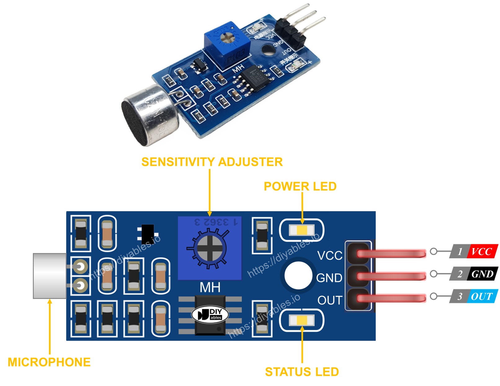
Additional features:
- Built-in potentiometer for adjusting sound sensitivity threshold
- Power LED indicator shows when the sensor is powered
- Status LED indicator lights up when sound is detected
The Analog Sound Sensor Pinout
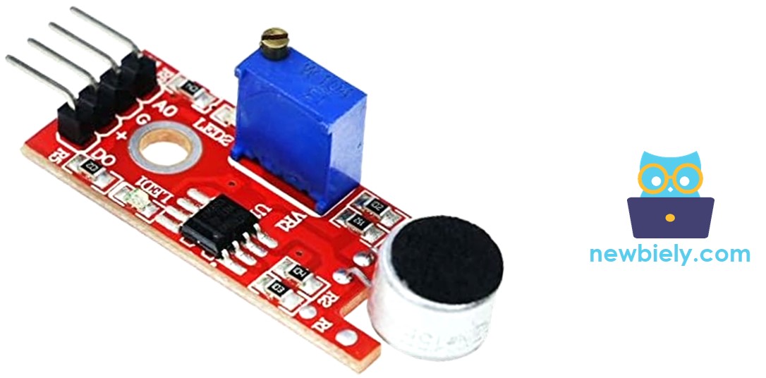
The analog sound sensor has four connection pins offering both digital and analog outputs.
- + pin: Connect to 5V power supply
- G pin: Connect to ground (0V)
- DO pin: Digital output - outputs HIGH when quiet, LOW when sound detected - connect to ESP32 S3 digital input pin
- AO pin: Analog output - outputs analog voltage representing sound level - connect to ESP32 S3 analog input pin
How It Works
The sound sensor module detects sound and converts it to electrical signals your ESP32 S3 can read. The digital output toggles LOW when sound exceeds the sensitivity threshold and returns HIGH when the environment is quiet, while the analog output provides a continuous voltage representing the current sound level. You can tune the detection threshold at any time by rotating the onboard potentiometer — clockwise to require louder sounds, counterclockwise to detect quieter sounds.
Digital output behavior:
- When sound is detected: Output pin goes LOW
- When no sound (quiet): Output pin stays HIGH
- Sensitivity threshold adjustable via onboard potentiometer
Wiring Diagram
Connect your sound sensor to the ESP32 S3 following the diagram below, then double-check every connection before applying power. The digital sound sensor requires only three wires, while the analog version adds a fourth wire for the AO pin.
Safety Notes
Always verify that VCC connects to the correct voltage rail (3.3V or 5V) before powering on — reversing the power polarity can damage the sensor module. Keep jumper wires tidy and away from the potentiometer adjustment screw so accidental contact does not shift your sensitivity setting during testing.
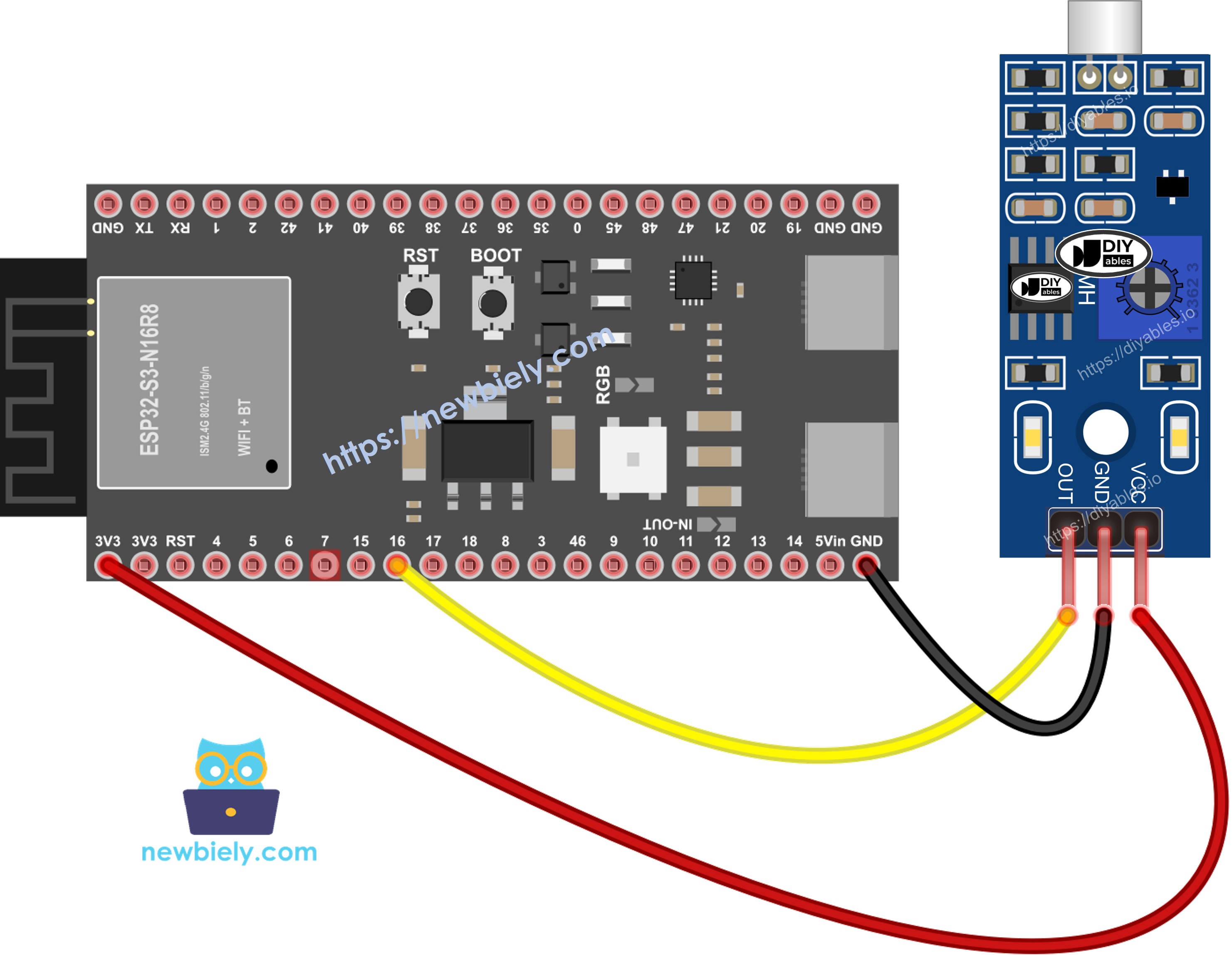
This image is created using Fritzing. Click to enlarge image
| Sound Sensor Pin | ESP32 S3 Pin |
|---|---|
| VCC | 3.3V or 5V |
| GND | GND |
| OUT (or DO) | 16 (GPIO16) |
How To Program For Sound Sensor
Programming the ESP32 S3 to read a sound sensor is straightforward — you configure one GPIO as a digital input, read its state in a loop, and interpret the result as sound detected or not detected. The following code demonstrates this approach with clear Serial Monitor output so you can verify the sensor is working before building your larger project.
Step 1 - Initialize the pin:
Step 2 - Read the sensor state:
ESP32 S3 Code - Detecting the sound
Detailed Instructions
- New to ESP32 S3? Complete our Getting Started with ESP32 S3 guide first.
- Check the wiring: Verify all connections match the wiring diagram above
- Copy the code: Copy the provided code and open it in Arduino IDE
- Select your board: Choose ESP32 S3 from the boards menu
- Upload the code: Click the Upload button to transfer code to your ESP32 S3
- Open Serial Monitor: Set baud rate to 115200 in the Serial Monitor
- Test the sensor: Clap your hands or make noise near the sound sensor
- Observe the output: Check the Serial Monitor for sound detection messages
- Adjust sensitivity: If needed, turn the potentiometer to fine-tune detection threshold
- Pro Tip: If the status LED stays constantly on or off regardless of sound, adjust the potentiometer slowly while making noise until the LED blinks in response to sound.
If the LED indicator stays constantly on or off even when sound is present, rotate the potentiometer to adjust the sound sensitivity threshold until the sensor responds correctly.
Now you can customize the code to trigger actions when sound is detected - activate an LED, control a relay to switch lights, or rotate a servo motor in response to sound. Check the application ideas and challenge sections below for inspiration.
Application and Project Ideas
The ESP32 S3's wireless capabilities and processing power open up a wide range of sound-activated applications beyond simple detection.
- Clap-activated switch: Build a clap-activated light switch using a relay module
- Sound-level meter: Create a sound-level meter display with an LED bar graph
- Knock detection lock: Design a knock-detection door lock system
- Pet feeder: Make a sound-triggered pet feeder or treat dispenser
- Noise monitor: Build a noise monitoring system for quiet zones
- Voice alert system: Create a voice-activated notification system with buzzer alerts
Video Tutorial
Watch the step-by-step video walkthrough for this ESP32 S3 project below.
Challenge Yourself
These challenges let you progressively extend your ESP32 S3 sound sensor project from simple LED feedback to sophisticated pattern recognition.
- Beginner: Add an LED that lights up when sound is detected and turns off when quiet
- Beginner: Display the sound state on an LCD screen instead of Serial Monitor
- Intermediate: Create a clap counter that counts the number of claps detected within a time window
- Intermediate: Combine the sound sensor with a relay to build a clap-activated lamp
- Advanced: Build a sound pattern recognition system that responds to specific clap sequences (e.g., double-clap vs triple-clap)
Troubleshooting
If your ESP32 S3 sound sensor isn't working properly, try these solutions.
Common issues and fixes:
- Reduce vibrations: Mount the sound sensor on a stable, vibration-free surface - mechanical vibrations and wind noise interfere with detection accuracy
- Check sensing range: This sound sensor detects sound within approximately 10 inches - move closer to the sensor when testing
- Verify power supply: Ensure clean, noise-free power - the sound sensor's analog components are sensitive to power supply interference
- Adjust sensitivity: Rotate the potentiometer while testing until the sensor responds appropriately to your sound level
- Check wiring: Verify all connections match the wiring diagram - loose or incorrect connections cause erratic behavior
- Test LED indicators: Power LED should be on constantly; status LED should blink when sound is detected