
ESP32 S3 - TFT LCD Touch Display SPI
Let's build a project that brings a full-color SPI TFT display to life on an ESP32 S3. The ESP32 S3 is a powerful dual-core microcontroller with Wi-Fi, Bluetooth, and abundant GPIO — and its hardware SPI bus makes it straightforward to run a high-speed TFT display at the full rates the panel supports.
What you'll build:
- A wired connection between an ESP32 S3 and an SPI TFT display.
- A shapes demo using the Adafruit GFX drawing API.
- A text and number display example.
- A bitmap image viewer reading from program memory (PROGMEM).
- A bitmap image viewer reading images from an SD card.
- A custom external font demo.
- A touch coordinate reader using an XPT2046 controller.
- A touch-draw application (finger painting on screen).
- An interactive touch button interface.
- A touch screen calibration tool.
- A custom SPI bus example using a secondary SPI bus on the ESP32 S3.
This project covers both touch and non-touch SPI TFT LCD displays. It works with 1.3, 1.54, 2.2, 2.4, 2.8, 3.2, and 3.5 inch panels driven by ILI9341, ILI9488, or ST7789 controller chips.
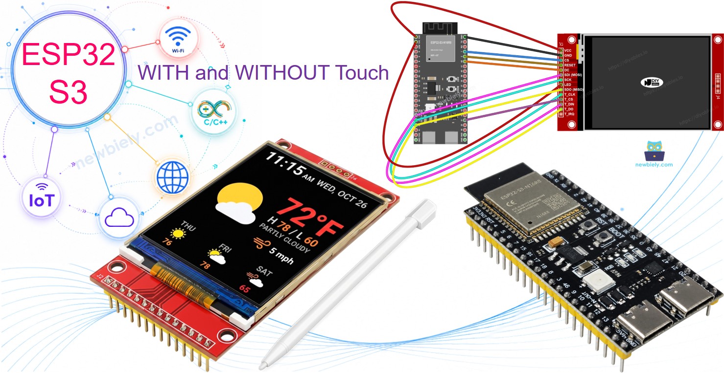
Hardware Preparation
Or you can buy the following kits:
| 1 | × | DIYables ESP32 S3 Starter Kit (ESP32 S3 included) | |
| 1 | × | DIYables Sensor Kit (18 sensors/displays) |
Additionally, some of these links are for products from our own brand, DIYables .
What Is the SPI TFT Display?
An SPI TFT module pairs a color LCD with a driver IC that accepts drawing commands over a 4-wire SPI bus. The DIYables_TFT_SPI library supports three common controller chips, each offering different color depth and speed characteristics.
Key Specifications
- ILI9341 - 16-bit RGB565 color, up to 40 MHz SPI.
- ILI9488 - 18-bit RGB666 color over SPI, up to 24 MHz.
- ST7789 - 16-bit RGB565 color, up to 40 MHz SPI.
Recommendation: If you have not yet purchased a display, we recommend the ST7789 driver. It is widely available, runs at full 40 MHz SPI speed, and is the most straightforward choice for new projects.
Drawing is handled through the Adafruit GFX API, which includes shapes, text, custom fonts, and bitmap output.
Note: The ESP32 S3 uses 3.3V logic. Most SPI TFT modules operate at 3.3V. Verify your module's voltage spec before wiring.
Pinout
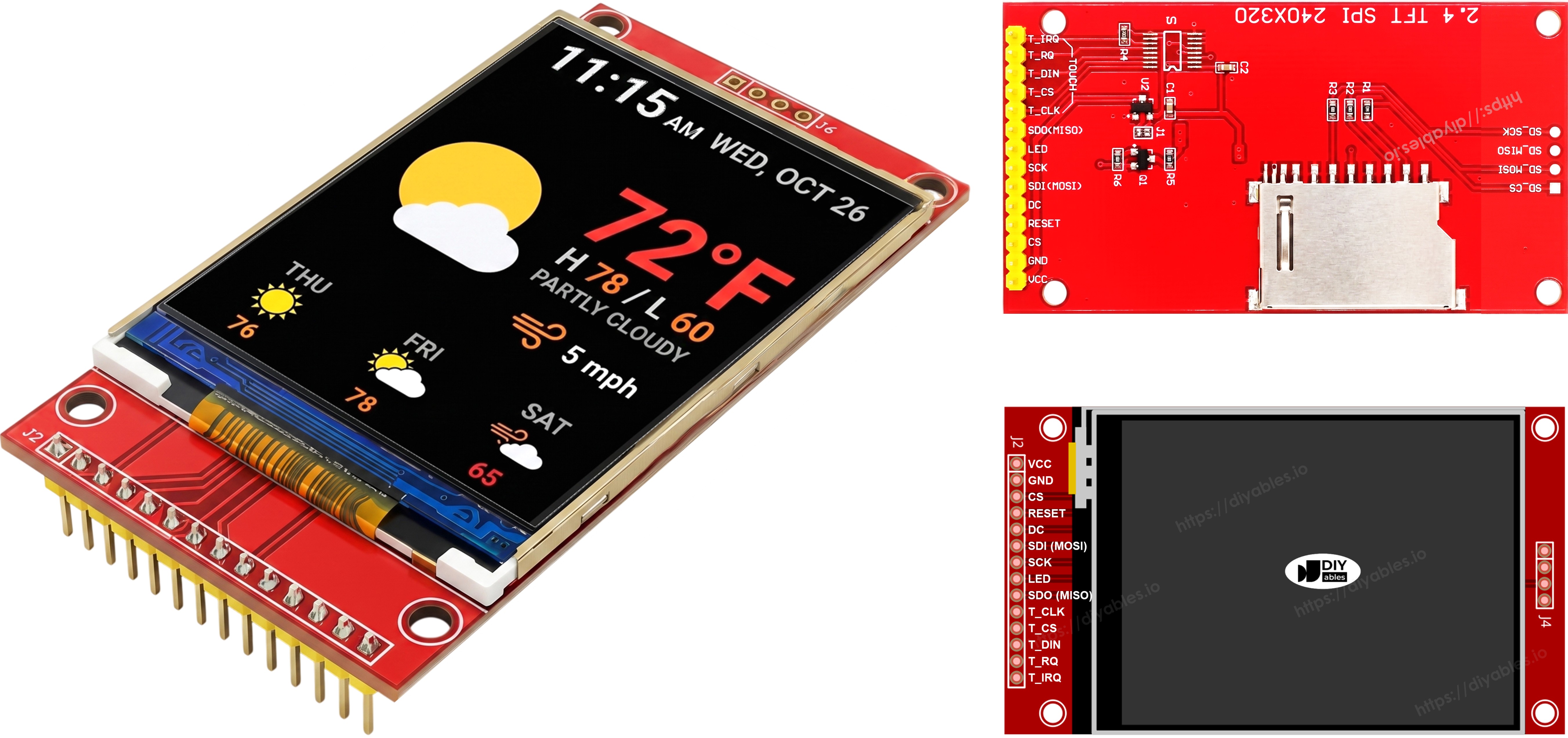
Most SPI TFT LCD displays expose the following pins, split across the display controller, optional SD card slot, and optional XPT2046 touch controller.
Display pins:
| Pin | Function |
|---|---|
| VCC | Power supply |
| GND | Ground |
| CS | Chip Select — pulled low to select the display on the SPI bus |
| DC / RS | Data / Command select — high for pixel data, low for commands |
| RST | Hardware reset — optional; tie to 3.3V if unused |
| MOSI / SDI / SDA | SPI data in (MCU → display) |
| SCK / CLK | SPI clock |
| MISO / SDO | SPI data out (display → MCU) — optional for display-only use |
| LED / BL / BLK | Backlight power — connect to 3.3V or a PWM pin for dimming |
SD card pins (if your application needs to access the SD card):
| Pin | Function |
|---|---|
| SD_CS / TF_CS | SD card Chip Select |
| MOSI / SDI | MOSI — data from MCU to SD card |
| SCK / CLK | SCK — SPI clock |
| MISO / SDO | MISO — data from SD card to MCU |
For TFT displays that support touch, there are additional touch pins (if your application uses the touch function and the display supports it):
| Pin | Function |
|---|---|
| T_CS | Touch controller Chip Select |
| T_CLK | SCK — SPI clock |
| T_DIN | MOSI — data from MCU to touch controller |
| T_DO | MISO — data from touch controller to MCU |
| T_IRQ | Touch interrupt — optional; signals when the screen is being touched |
Note: Some non-touch display modules also expose T_CS, T_CLK, T_DIN, T_DO, and T_IRQ pins. These are non-functional on those boards — the touch controller IC is not populated. They appear because the PCB reuses the same layout as the touch-enabled version to reduce manufacturing variants.
Wiring Diagram
Note — SDO (MISO) is optional: The SDO (MISO) line only carries data from the display back to the board. None of the example code in this tutorial reads from the display, so this pin can be left unconnected. On modules where the touch controller shares the same SPI bus, a connected SDO line can interfere with communication, so leaving it unconnected is recommended.
Without Touch
Connect MOSI to GPIO11, SCK to GPIO12, MISO to GPIO13 on the ESP32 S3. CS, DC, and RST can be any available GPIO — GPIO1, GPIO42, GPIO2 are used in the examples.
Display:
| TFT Pin | ESP32 S3 Pin | Description |
|---|---|---|
| VCC | 3.3V | Power supply (3.3V only) |
| GND | GND | Ground |
| CS | GPIO1 | Chip Select |
| DC / RS | GPIO42 | Data / Command select |
| RST | GPIO2 | Reset (optional) |
| MOSI / SDI | GPIO11 | Hardware SPI MOSI |
| SCK | GPIO12 | Hardware SPI clock |
| MISO / SDO | GPIO13 | Hardware SPI MISO (optional) |
| LED / BL | 3.3V | Backlight power |
SD card (if your application needs to access the SD card):
| SD Pin | ESP32 S3 Pin | Description |
|---|---|---|
| SD_CS / TF_CS | any free GPIO | SD card Chip Select |
| MOSI / SDI | GPIO11 | Shared with display MOSI (GPIO11) |
| SCK / CLK | GPIO12 | Shared with display SCK (GPIO12) |
| MISO / SDO | GPIO13 | Shared with display MISO (GPIO13) |
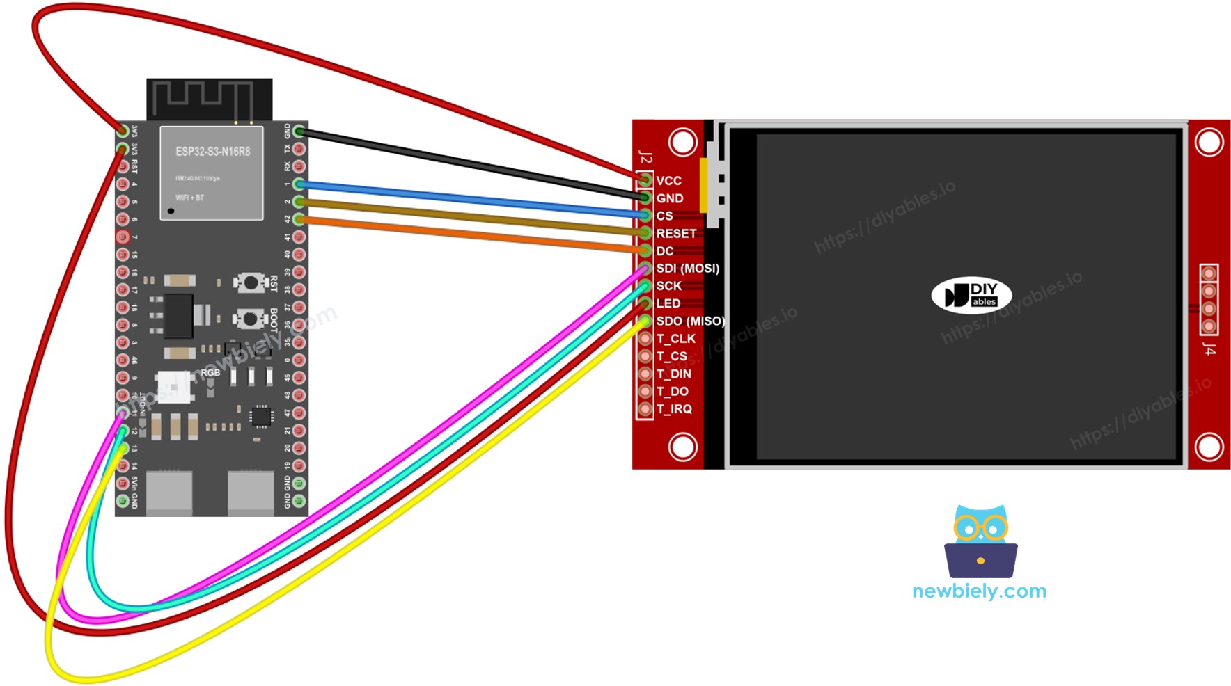
This image is created using Fritzing. Click to enlarge image
With Touch
Connect the XPT2046 touch controller to the ESP32 S3 SPI bus, sharing GPIO11, GPIO12, and GPIO13 with the display.
Display:
| TFT Pin | ESP32 S3 Pin | Description |
|---|---|---|
| VCC | 3.3V | Power supply (3.3V only) |
| GND | GND | Ground |
| CS | GPIO1 | Chip Select |
| DC / RS | GPIO42 | Data / Command select |
| RST | GPIO2 | Reset (optional) |
| MOSI / SDI | GPIO11 | Hardware SPI MOSI |
| SCK | GPIO12 | Hardware SPI clock |
| MISO / SDO | GPIO13 | Hardware SPI MISO (optional) |
| LED / BL | 3.3V | Backlight power |
Touch controller (if your application uses the touch function and the display supports it):
| Touch Pin | ESP32 S3 Pin | Description |
|---|---|---|
| T_CS | GPIO21 | Touch Chip Select |
| T_IRQ | any free GPIO | Touch interrupt (optional) |
| T_DIN | GPIO11 | Shared with display MOSI (GPIO11) |
| T_CLK | GPIO12 | Shared with display SCK (GPIO12) |
| T_DO | GPIO13 | Shared with display MISO (GPIO13) |
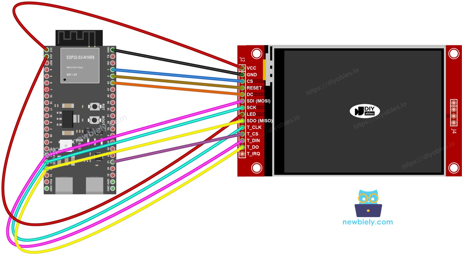
This image is created using Fritzing. Click to enlarge image
If your MCU has two or more hardware SPI interfaces, you can assign each peripheral (display, SD card, touch controller) to its own dedicated SPI bus. If your MCU has only one hardware SPI interface, all three peripherals share the same three data lines (MOSI, SCK, MISO). Each peripheral has its own CS pin, so only one is active at a time. The DIYables_TFT_SPI library manages both the display and the XPT2046 touch controller through a single API — no separate SPI library is needed for the touch side.
Library Installation
- Connect the ESP32 S3 board to your computer through its USB-C port.
- Open Arduino IDE. Select your ESP32 S3 board variant from the board menu and pick the correct COM port.
- Open the Libraries panel.
- Search for "DIYables_TFT_SPI". Locate the DIYables entry.
- Click Install and accept all dependency installations.
- Search for DIYables TFT SPI created by DIYables.io and click the Install button.
Project Foundation
The following code provides the base sketch for every ESP32 S3 TFT project with this library. It initializes the display on the hardware SPI bus and sets the screen orientation before the drawing loop begins.
Let's Build - Draw Shapes
The DrawShapes example draws the full range of Adafruit GFX primitives: circles, triangles, rectangles, rounded rectangles, and lines. The following code cycles through each shape type using contrasting colors so you can verify every drawing function at a glance.
Upload and Test
- Wire the TFT module to the ESP32 S3 using the table above.
- Plug in the USB-C cable.
- In Arduino IDE, select the board and port, paste the code, and press Upload.
- After uploading, the display fills with a loop of colored shapes.
Drawing API Reference
| Method | Purpose | Usage |
|---|---|---|
| begin() | Initialize the display. | TFT_display.begin(); |
| setRotation(r) | Set screen orientation 0-3. | TFT_display.setRotation(1); |
| fillScreen(color) | Fill entire screen with one color. | TFT_display.fillScreen(BLACK); |
| colorRGB(r,g,b) | Build a 16-bit color value. | colorRGB(255,128,0) |
| fillCircle(x,y,r,color) | Solid filled circle. | TFT_display.fillCircle(120,160,60,RED); |
| fillRect(x,y,w,h,color) | Solid rectangle. | TFT_display.fillRect(0,0,100,50,BLUE); |
| drawLine(x0,y0,x1,y1,color) | Straight line between two points. | TFT_display.drawLine(0,0,320,240,WHITE); |
Let's Build - Show Text and Number
The ShowTextAndNumber example uses the Adafruit GFX text engine to print strings and numeric values at adjustable sizes and colors. The following code demonstrates multiple font sizes and color combinations so you can build readable on-screen dashboards.
Upload and Test
- Wire and upload as above.
- The display shows multiple lines of text and numbers in different colors and sizes.
Drawing API Reference
| Method | Purpose | Usage |
|---|---|---|
| setTextColor(color) | Sets the text foreground color. | TFT_display.setTextColor(WHITE); |
| setTextSize(size) | Scales text. Size 1 = 6×8 px, size 2 = 12×16 px. | TFT_display.setTextSize(2); |
| setCursor(x, y) | Places the text cursor at pixel (x, y). | TFT_display.setCursor(10, 20); |
| print(value) | Prints a string or number at the cursor. | TFT_display.print("ESP32 S3!"); |
| println(value) | Prints and advances cursor to the next line. | TFT_display.println(42); |
Let's Build - Draw Image
Let's build an image viewer. The DrawImage example loads a full-color RGB565 bitmap from the ESP32 S3's program flash and renders it on the display. The pixel data is declared in bitmap.h as a const uint16_t array with PROGMEM. On the ESP32 S3, PROGMEM data is mapped from flash into the virtual address space, so the image draws without consuming any heap RAM.
Copy bitmap.h into the sketch folder before compiling.
Upload and Test
- Place bitmap.h in the same folder as the sketch.
- Wire the TFT module to the ESP32 S3 as shown above (MOSI=GPIO11, SCK=GPIO12, MISO=GPIO13, CS=GPIO1, DC=GPIO42, RST=GPIO2). Use 3.3V for VCC.
- Plug in the USB-C cable.
- In Arduino IDE, select the board and port, press Upload.
- The display renders the bitmap image from flash.
Drawing API Reference
| Method | Purpose | Usage |
|---|---|---|
| drawRGBBitmap(x,y,bitmap,w,h) | Draws an RGB565 PROGMEM bitmap with its top-left corner at (x, y). | TFT_display.drawRGBBitmap(0, 0, myImage, 240, 320); |
| fillScreen(color) | Clears the display before drawing the image. | TFT_display.fillScreen(BLACK); |
Let's Build - Draw Image SD Card
Let's build an SD card image viewer. The DrawImageSDcard example reads a raw RGB565 binary image from a micro SD card and streams the pixel data to the display in chunks. The ESP32 S3 handles both the SD card and the display on the same SPI bus, switching CS lines to arbitrate between them.
Wire the SD module to GPIO11 (MOSI), GPIO12 (SCK), GPIO13 (MISO). Define a separate CS pin for the SD module as SD_CS_PIN in the sketch.
Upload and Test
- Wire the SD module to the ESP32 S3 SPI bus. Share GPIO11/12/13 with the display. Connect SD CS to the pin defined as SD_CS_PIN.
- Copy a raw RGB565 binary image file to the root of the SD card. Dimensions must match your panel.
- Plug in the USB-C cable.
- In Arduino IDE, select board and port, press Upload.
- The display renders the image streamed from the SD card.
Drawing API Reference
| Method | Purpose | Usage |
|---|---|---|
| startWrite() | Opens a direct SPI write session and asserts the display CS. | TFT_display.startWrite(); |
| setAddrWindow(x0,y0,x1,y1) | Defines the rectangular pixel write region on the panel. | TFT_display.setAddrWindow(0, 0, 239, 319); |
| pushColors(buf, len) | Sends a buffer of RGB565 pixel values to the display. | TFT_display.pushColors(buf, 512); |
| endWrite() | Closes the SPI session and releases the display CS. | TFT_display.endWrite(); |
Let's Build - Use External Font
Let's build a custom text display. The UseExternalFont example replaces the default 5×7 pixel font with a sharper Adafruit GFX-compatible outline font. One call to setFont() is all it takes to upgrade the typography. Calling setFont(NULL) restores the original built-in font at any time.
Upload and Test
- Wire the TFT module to the ESP32 S3 as shown above.
- Plug in the USB-C cable.
- In Arduino IDE, select board and port, press Upload.
- The display renders text in the custom font.
Drawing API Reference
| Method | Purpose | Usage |
|---|---|---|
| setFont(&FontName) | Activates a custom GFX-compatible font. Pass NULL to restore the built-in 5×7 font. | TFT_display.setFont(&FreeSans12pt7b); |
| setCursor(x, y) | Positions the text cursor at the given pixel coordinate. | TFT_display.setCursor(10, 40); |
| setTextColor(color) | Sets the foreground color for subsequent text. | TFT_display.setTextColor(WHITE); |
| print(text) | Prints a string at the cursor using the active font. | TFT_display.print("ESP32 S3 Project"); |
Let's Build - Touch Get Point
Let's build a touch coordinate reader. The TouchGetPoint example initializes the XPT2046 on the ESP32 S3's SPI bus and prints raw ADC values to the Serial Monitor whenever the screen is pressed. This is the first step toward a touch-aware project: understanding the raw value range your panel produces.
Wiring (all signals at 3.3V):
| Touch Pin | ESP32 S3 Pin | Description |
|---|---|---|
| T_CLK | GPIO12 | SCK — shared with display |
| T_DIN | GPIO11 | MOSI — shared with display |
| T_DO | GPIO13 | MISO — shared with display |
| T_CS | GPIO21 | Touch Chip Select |
| T_IRQ | GPIO45 | Touch interrupt (optional) |
Upload and Test
- Wire the XPT2046 to the ESP32 S3 SPI bus, sharing GPIO11/12/13 with the display. T_CS→GPIO21, T_IRQ→GPIO45.
- Plug in the USB-C cable.
- In Arduino IDE, select board and port, press Upload.
- Open the Serial Monitor at 9600 baud. Touch the display to see raw X, Y, and Z values printed.
Drawing API Reference
| Method | Purpose | Usage |
|---|---|---|
| initTouchSPI(cs, irq) | Initializes the XPT2046 on the shared SPI bus. Pass -1 for irq if the interrupt pin is not connected. | TFT_display.initTouchSPI(21, 45); |
| readTouchRaw(x, y, z) | Returns raw ADC values from the controller with no calibration applied. Returns true when pressed. | TFT_display.readTouchRaw(x, y, z); |
Let's Build - Touch Draw
Let's build a finger-painting app. The TouchDraw example combines the XPT2046 touch controller with the display's drawing API. Each touch position maps to a calibrated pixel coordinate and a small filled circle is drawn there, creating a stroke as the finger moves.
Upload and Test
- Wire the XPT2046 to the ESP32 S3 as described in the Touch Get Point section above.
- Plug in the USB-C cable.
- In Arduino IDE, select board and port, press Upload.
- Drag a finger across the display to paint on screen.
Drawing API Reference
| Method | Purpose | Usage |
|---|---|---|
| initTouchSPI(cs, irq) | Initializes the XPT2046 on the shared SPI bus. | TFT_display.initTouchSPI(21, 45); |
| setTouchCalibration(minX,maxX,minY,maxY) | Maps raw ADC values to screen pixel coordinates. Get the four values from the TouchCalibration example. | TFT_display.setTouchCalibration(200, 3800, 300, 3700); |
| setTouchInvertX(invert) / setTouchInvertY(invert) | Flips the touch axis when X or Y is mirrored on your specific panel or batch. Call BEFORE setTouchCalibration(). | TFT_display.setTouchInvertY(true); |
| getTouch(x, y) | Returns calibrated touch coordinates in screen pixels. Returns true while the screen is pressed. | if (TFT_display.getTouch(x, y)) { ... } |
| fillCircle(x, y, r, color) | Draws a small dot at the touch position to build up the painting. | TFT_display.fillCircle(x, y, 3, RED); |
Let's Build - Touch Calibration
Let's build a calibration tool. The TouchCalibration example guides you through measuring the raw ADC extremes of your XPT2046 panel. Touch each corner of the display as prompted and record the printed minimum and maximum X and Y values. Those four numbers are the constants for setTouchCalibration() in all other touch projects.
Upload and Test
- Wire the XPT2046 to the ESP32 S3 as described in the Touch Get Point section.
- Plug in the USB-C cable.
- In Arduino IDE, select board and port, press Upload.
- Open the Serial Monitor at 9600 baud. Follow the on-screen prompts and touch each corner.
- Record the four printed values and use them in setTouchCalibration() in your other touch projects.
Drawing API Reference
| Method | Purpose | Usage |
|---|---|---|
| initTouchSPI(cs, irq) | Initializes the XPT2046 touch controller. | TFT_display.initTouchSPI(21, 45); |
| readTouchRaw(x, y, z) | Reads raw ADC values to determine the calibration range. | TFT_display.readTouchRaw(x, y, z); |
| setTouchCalibration(minX,maxX,minY,maxY) | Stores calibration constants so getTouch() maps raw values to pixel coordinates correctly. | TFT_display.setTouchCalibration(200, 3800, 300, 3700); |
| setTouchInvertX(invert) / setTouchInvertY(invert) | Flips the touch axis when X or Y is mirrored on your specific panel or batch. Call BEFORE running calibration so the stored values match your panel. | TFT_display.setTouchInvertY(true); |
Let's Build - Custom SPI
Let's build on a custom SPI bus. The ESP32 S3 supports multiple hardware SPI controllers. The CustomSPI example shows how to create an SPIClass instance for a secondary SPI bus and pass it to the display constructor. This frees the primary SPI bus for other peripherals such as SD cards or sensor modules that share SPI.
Upload and Test
- Wire the TFT display to the ESP32 S3 pins matching the custom SPI bus you define in the sketch.
- Plug in the USB-C cable.
- In Arduino IDE, select board and port, press Upload.
- The display starts on the selected SPI bus and shows a color-bar pattern to confirm success.
Drawing API Reference
| Method | Purpose | Usage |
|---|---|---|
| SPIClass myBus(HSPI) | Create an SPIClass instance bound to a secondary SPI controller. | SPIClass SPI2_bus(HSPI); |
| DIYables_ILI9341_SPI(w,h,cs,dc,rst,spi) | Constructor accepting a pointer to any SPIClass. Defaults to &SPI when omitted. | DIYables_ILI9341_SPI tft(240, 320, 10, 9, 8, &SPI2_bus); |
| begin() | Initializes the display on the configured SPI bus. | TFT_display.begin(); |
Detailed Instructions
- New to ESP32 S3? Complete our Getting Started with ESP32 S3 guide first.
- Install the DIYables_TFT_SPI library via the Arduino IDE Libraries panel.
- Wire the TFT display to the ESP32 S3 SPI pins using the wiring table for your use case (with or without touch).
- Open the sketch for the sub-project you want to build and verify the pin defines match your wiring.
- Select the correct constructor line for your driver chip (ILI9341, ILI9488, or ST7789) and comment out the others.
- Select the ESP32 S3 board and correct COM port in Arduino IDE, then press Upload.
- For touch projects, run the TouchCalibration example first and note the four printed values before loading your main sketch.
- Pro Tip: Share GPIO11, GPIO12, and GPIO13 across the display, SD card, and touch controller — the library handles bus arbitration through individual CS pins automatically.
Serial Monitor Output
Open the Serial Monitor at 9600 baud for touch-enabled sketches. Expected output during a touch session:
Applications
SPI TFT displays paired with the ESP32 S3 are well suited to embedded projects that need a compact, high-color visual output. Some practical uses include:
- Dashboard: Display real-time sensor readings such as temperature, humidity, and pressure on a color-coded gauge screen.
- IoT Monitor: Show live data from MQTT topics or REST APIs, updating the screen whenever new values arrive over Wi-Fi.
- Touch Control Panel: Build a multi-button UI for controlling relays, motors, or smart-home devices without any physical buttons.
- Portable Logger: Combine the SD card reader with the display to log and graph sensor data to a micro SD card with a live chart on screen.
- Digital Signage: Cycle through bitmap images stored on SD card to create a low-power advertising or information display.
Video Tutorial
Watch the step-by-step video walkthrough for this ESP32 S3 project below.
Challenges
Take your ESP32 S3 TFT display project further by trying these progressively harder extensions. Each challenge reinforces a different aspect of the library and hardware.
- Beginner: Modify the DrawShapes sketch to draw your initials using lines and rectangles in your two favorite colors.
- Beginner: Change the ShowTextAndNumber sketch to display a live millisecond counter that updates every 500 ms using millis().
- Intermediate: Combine the DrawImageSDcard and ShowTextAndNumber examples to overlay a label onto a bitmap image loaded from SD card.
- Intermediate: Build a two-button touch interface that toggles an LED connected to a GPIO pin — one button ON, one button OFF — with the button color reflecting the current LED state.
- Advanced: Create a multi-screen touch UI with a home screen and two sub-screens, navigating between them with on-screen back and forward buttons, each screen displaying different sensor data.
Troubleshoot
| Issue | Cause | Fix |
|---|---|---|
| Blank screen | Wrong SPI pins or wrong power | Use the correct hardware SPI pins for your ESP32 S3 variant; check VCC is 3.3V |
| Garbled image | Wrong driver active | Uncomment only the matching constructor |
| Image is offset | Constructor width/height mismatch | Match values to your actual panel dimensions |
| No touch response | Missing calibration data | Run TouchCalibration example and copy the printed values |
| Port not visible | USB driver missing | Install the correct USB driver for your ESP32 S3 board |
Platform Support
The library is built on Arduino's standard SPI API and supports all Arduino-compatible ESP32 S3 variants (architectures=*).