
ESP32 S3 - Measure Voltage
In this guide, you will learn how to measure voltage ranging from 0 V to 16.5 V using a voltage sensor with an ESP32 S3. We will walk through the wiring, the code, and each step in detail so you can follow along even if you are new to the platform.
What you'll build:
- A circuit connecting a voltage sensor to the ESP32 S3
- Code that reads the raw ADC value from the sensor output
- A voltage conversion that maps the ADC reading to real volts
- Serial Monitor output that displays live voltage readings
Hardware Preparation
Or you can buy the following kits:
| 1 | × | DIYables ESP32 S3 Starter Kit (ESP32 S3 included) | |
| 1 | × | DIYables Sensor Kit (18 sensors/displays) |
Additionally, some of these links are for products from our own brand, DIYables .
Overview of Voltage Sensor
A voltage sensor is a ready-made voltage divider circuit that uses specific resistors to make measuring voltage straightforward. It contains two resistors — 30 kΩ and 7.5 kΩ — that scale down the input voltage to a level your ESP32 S3's ADC can safely read. When the ADC reference voltage is 3.3 V, the sensor can measure voltages from 0 V to 16.5 V DC.
Key Specifications
- Input voltage range: 0 V to 25 V DC (with 5 V ADC reference) / 0 V to 16.5 V DC (with 3.3 V ADC reference)
- Resistor divider: 30 kΩ (R1) and 7.5 kΩ (R2)
- Output voltage: proportional to the input, scaled to fit the ADC range
Pinout
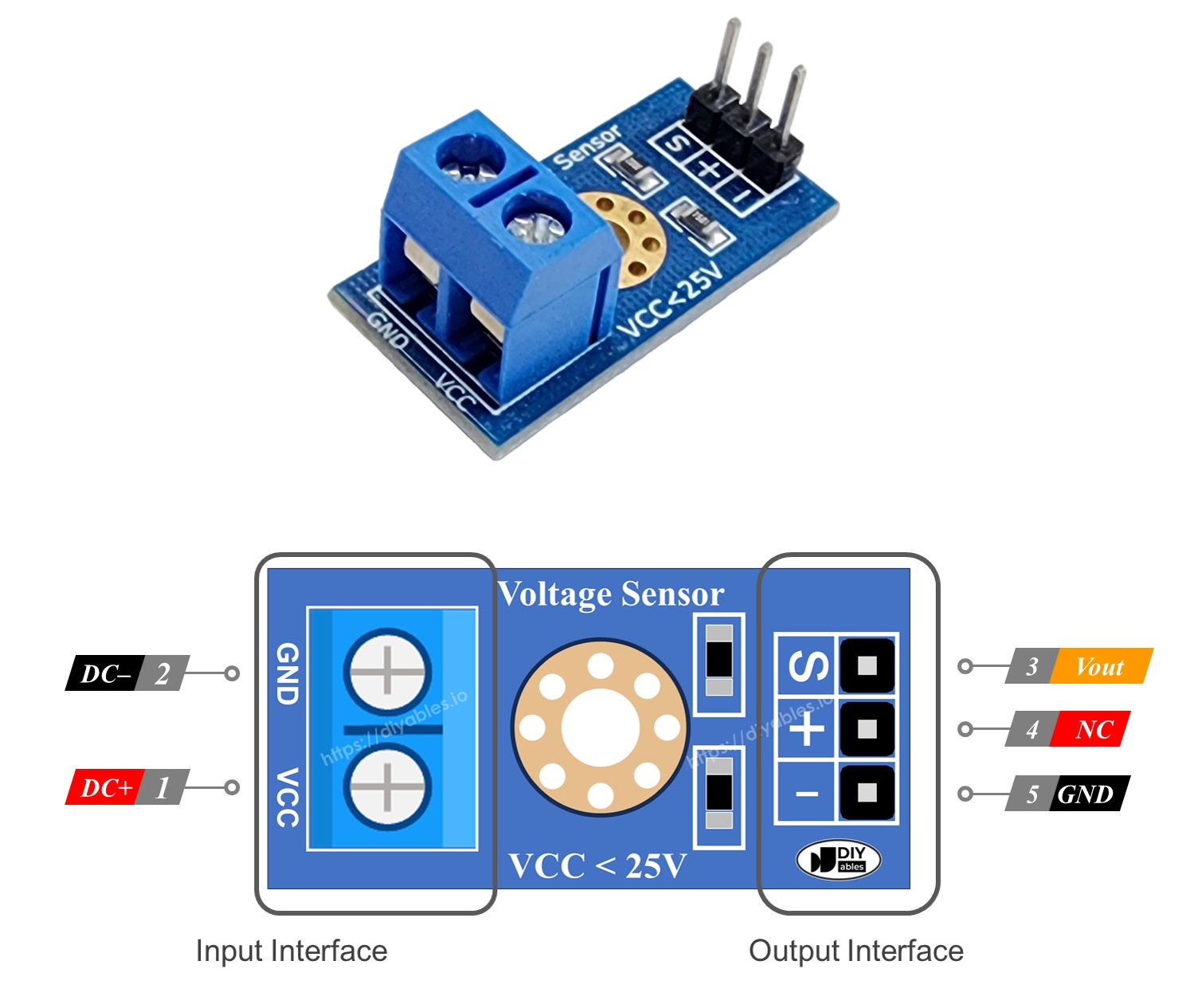
A voltage sensor comes with two groups of pins. The input interface connects to the circuit you want to measure, while the output interface connects to the ESP32 S3.
- VCC pin (input): Connect to the positive (higher voltage) measurement point.
- GND pin (input): Connect to the negative (lower voltage) measurement point.
- Vout / S pin (output): Connect to an ADC-capable GPIO on the ESP32 S3.
- NC / + pin (output): Do not connect — this pin is unused.
- GND / - pin (output): Connect to the GND on the ESP32 S3.
Wiring Diagram
Connect the voltage sensor to your ESP32 S3 using jumper wires as shown in the diagram below. Make sure the Vout pin of the sensor goes to an ADC-capable GPIO so the ESP32 S3 can read the scaled voltage accurately.
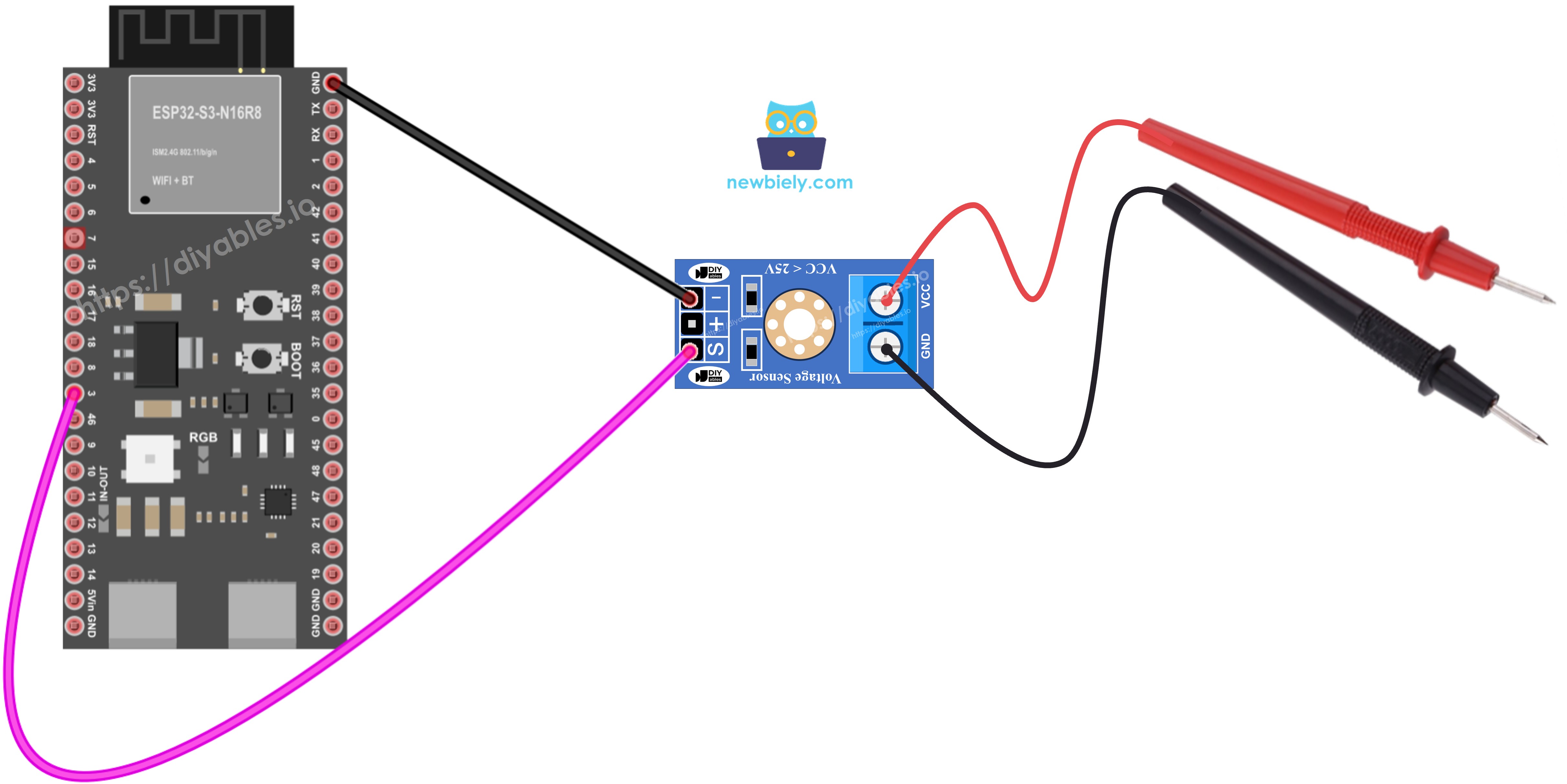
This image is created using Fritzing. Click to enlarge image
Safety Notes
The voltage sensor output is already scaled for the ESP32 S3's 3.3 V ADC input, so do not exceed 16.5 V on the sensor's input pins. Always double-check your wiring before applying power to avoid sending over-voltage to the ADC pin.
| Voltage Sensor Pin | ESP32 S3 Pin |
|---|---|
| Vout (S) | GPIO1 (or any ADC-capable GPIO) |
| GND (-) | GND |
ESP32 S3 Code
Reading voltage with the ESP32 S3 involves sampling the ADC, applying the sensor's divider ratio, and printing the result to the Serial Monitor. The following code performs all three steps and outputs a new measurement every second.
Detailed Instructions
- New to ESP32 S3? Complete our Getting Started with ESP32 S3 guide first.
- Connect the ESP32 S3 to the voltage sensor as shown in the wiring diagram.
- Connect the ESP32 S3 board to your PC via a USB cable.
- Open Arduino IDE on your PC.
- Select the right ESP32 S3 board and COM port in Arduino IDE.
- Copy the above code and paste it into the Arduino IDE.
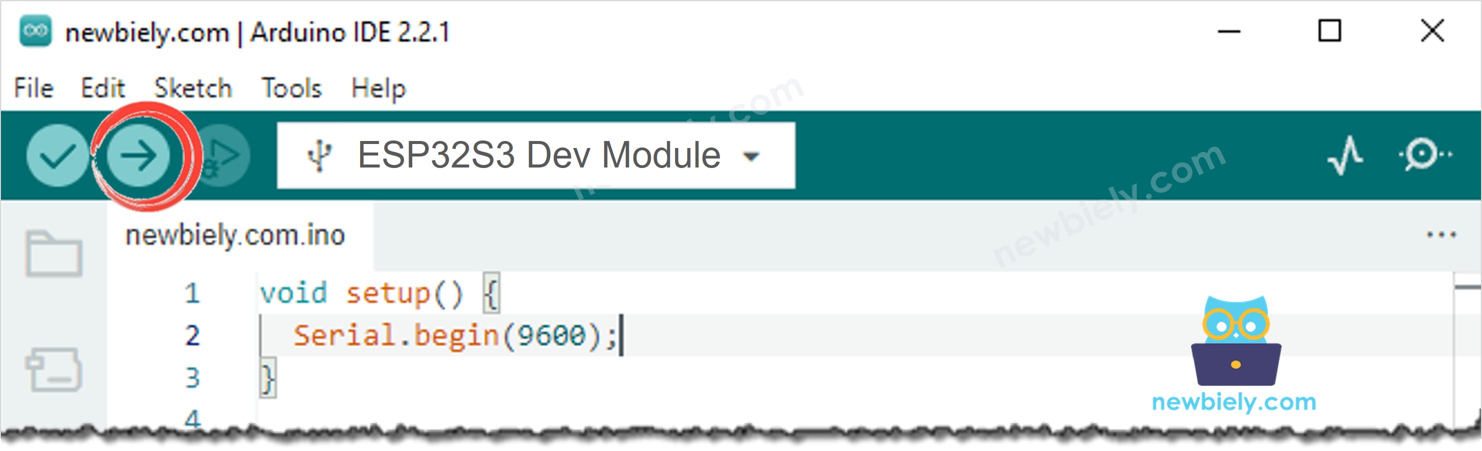
- Press the Upload button in Arduino IDE to compile and upload the code to the ESP32 S3.
- Open the Serial Monitor in Arduino IDE.
- Test by measuring 5 V and 3.3 V on the ESP32 S3 board.
- Observe the readings in the Serial Monitor.
- Pro Tip: Compare the displayed value against a known reference voltage (such as the ESP32 S3's 3.3 V rail) to quickly gauge the accuracy of your setup.
Serial Monitor
After uploading, the Serial Monitor will display a new voltage measurement each second. The following readings were captured in 2026 while measuring the ESP32 S3's 5 V and 3.3 V rails:
※ NOTE THAT:
You might notice that the measurement result is slightly different from the actual value. The code uses the analogRead() function to read values from the ADC connected to the voltage sensor. The ESP32 S3 ADC is suitable for projects that do not require high accuracy. For projects needing precise measurements, note:
- The ESP32 S3 ADC is not perfectly accurate and may need calibration. Each board can behave slightly differently.
- Calibration can be challenging for beginners and may not always yield exact results.
For high-precision projects, consider using an external ADC (e.g. ADS1115) with the ESP32 S3. If you still want to calibrate the ADC, refer to ESP32 ADC Calibration Driver.
Applications
Voltage measurement opens the door to a wide range of real-world monitoring and protection tasks with the ESP32 S3. Some practical applications include:
- Battery level indicator: Monitor a LiPo or lead-acid battery's state of charge and display it on an OLED or LED bar graph.
- Power supply monitoring: Continuously check a DC rail and trigger an alert if the voltage drops below a safe threshold.
- Solar panel monitoring: Track the output voltage of a solar panel to log energy generation data over time.
- Load testing: Measure the voltage drop across a load to calculate current draw and detect faults.
- Automotive diagnostics: Read a 12 V car battery voltage through the sensor's divider and warn when the battery is weak.
Video Tutorial
Watch the step-by-step video walkthrough for this ESP32 S3 project below.
Challenges
Now that you have a working voltage measurement circuit on the ESP32 S3, try extending the project with these exercises to deepen your understanding.
- Beginner: Change the GPIO pin used for the voltage sensor signal and update the code accordingly, then verify that the readings still display correctly.
- Intermediate: Add a threshold check in the code so that the ESP32 S3 lights up an LED when the measured voltage drops below a user-defined minimum value.
- Advanced: Log voltage readings to an SD card or send them over Wi-Fi to a web dashboard, creating a simple remote voltage monitoring system.