
ESP32 S3 - LED - Blink
Learn how to blink an LED with the ESP32 S3 in this beginner-friendly tutorial. This is one of the most fundamental Arduino projects, teaching you digital output control—an essential skill that forms the foundation of nearly every embedded systems project.
What you'll build:
- A circuit connecting an LED to the ESP32 S3
- An Arduino sketch that blinks the LED on and off
- A configurable blink interval you can adjust in code
- A reusable pattern for controlling any ON/OFF device
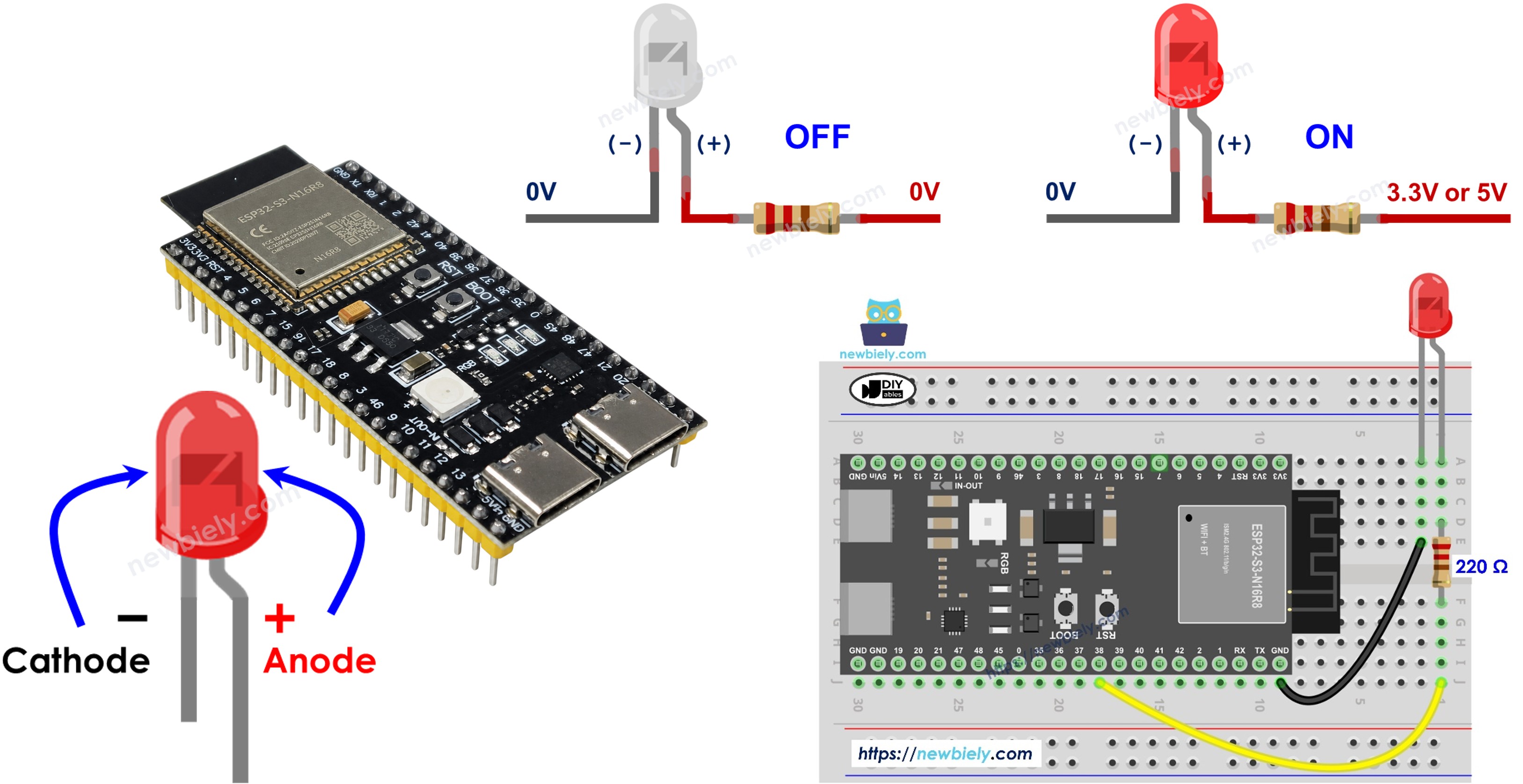
Hardware Preparation
Or you can buy the following kits:
| 1 | × | DIYables ESP32 S3 Starter Kit (ESP32 S3 included) | |
| 1 | × | DIYables Sensor Kit (18 sensors/displays) |
Additionally, some of these links are for products from our own brand, DIYables .
Buy Note: Use the LED Module for easier wiring. It includes an integrated resistor.
Overview of LED
An LED (Light Emitting Diode) is a semiconductor component that emits light when electric current flows through it in the correct direction. It is one of the most commonly used output devices in electronics, prized for its simplicity, low power consumption, and instant visual feedback.
Key Specifications
A standard LED operates at 1.8V to 3.3V with a typical current draw of around 20mA. LEDs are polarity-sensitive, meaning they only conduct electricity in one direction—connecting them backwards simply prevents them from lighting up. They are available in a wide range of colors including red, green, blue, yellow, and white, making them versatile for status indicators and decorative lighting alike.
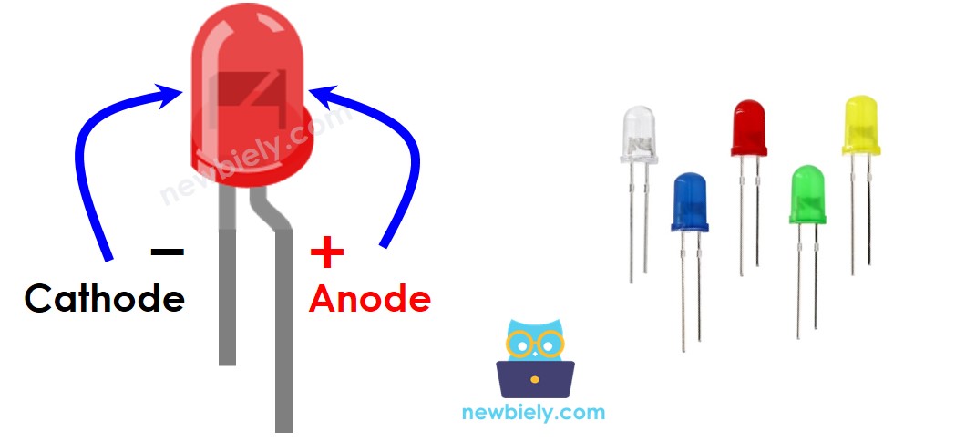
LED Pinout
The LED has two legs of different lengths that make polarity identification straightforward:
- Anode (+) pin: The longer leg; connect this to the control pin or VCC through a resistor
- Cathode (-) pin: The shorter leg; connect this pin to GND (0V)
How LED Works
After connecting the cathode(-) to GND:
- If we connect VCC to the anode(+), LED is ON.
- If we connect GND to the anode(+), LED is OFF.
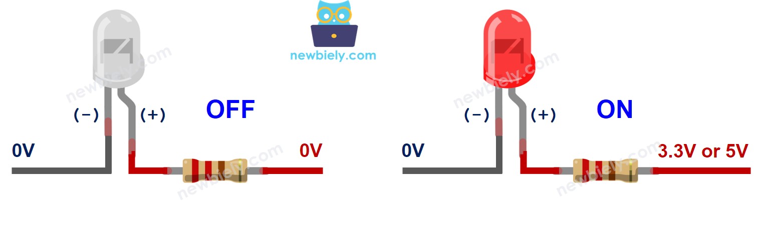
In addition, if a PWM signal is generated to the anode(+), the LED's brightness is changed in proportion to the PWM duty cycle. See more detailed in ESP32 S3 fade LED tutorial.
※ NOTE THAT:
- Usually, a resistor is required to protect LED from burning. The resistor can be placed between the anode(+) and VCC or between the cathode(-) and GND. The resistance value depends on the LED's specification.
- Some LEDs have a built-in resistor, so there is no need to use a resistor for them.
- For standard 5mm LEDs with ESP32 S3 (3.3V output), a 220 ohm resistor is recommended.
ESP32 S3 - LED
The ESP32 S3's GPIO pins can be programmed to output either VCC (3.3V) or GND (0V), making it straightforward to drive an LED directly from any available pin. The ESP32 S3 is well-suited for LED control projects because its GPIO system is flexible and programmable through the familiar Arduino digitalWrite() function. You can independently control multiple LEDs, each on its own pin, which opens the door to more complex lighting and signaling applications.
Wiring Diagram between LED and ESP32 S3
Connect the LED to your ESP32 S3 carefully, paying attention to the polarity of the LED legs. Run a wire from pin D7 through a 220 ohm resistor to the anode of the LED, then connect the cathode directly to any GND pin on the board.
Safety Notes
Always use a current-limiting resistor (220 ohm) in series with the LED to prevent excessive current from damaging either the LED or the ESP32 S3's GPIO pin. Connecting the LED without a resistor can permanently damage the GPIO pin or the LED itself.
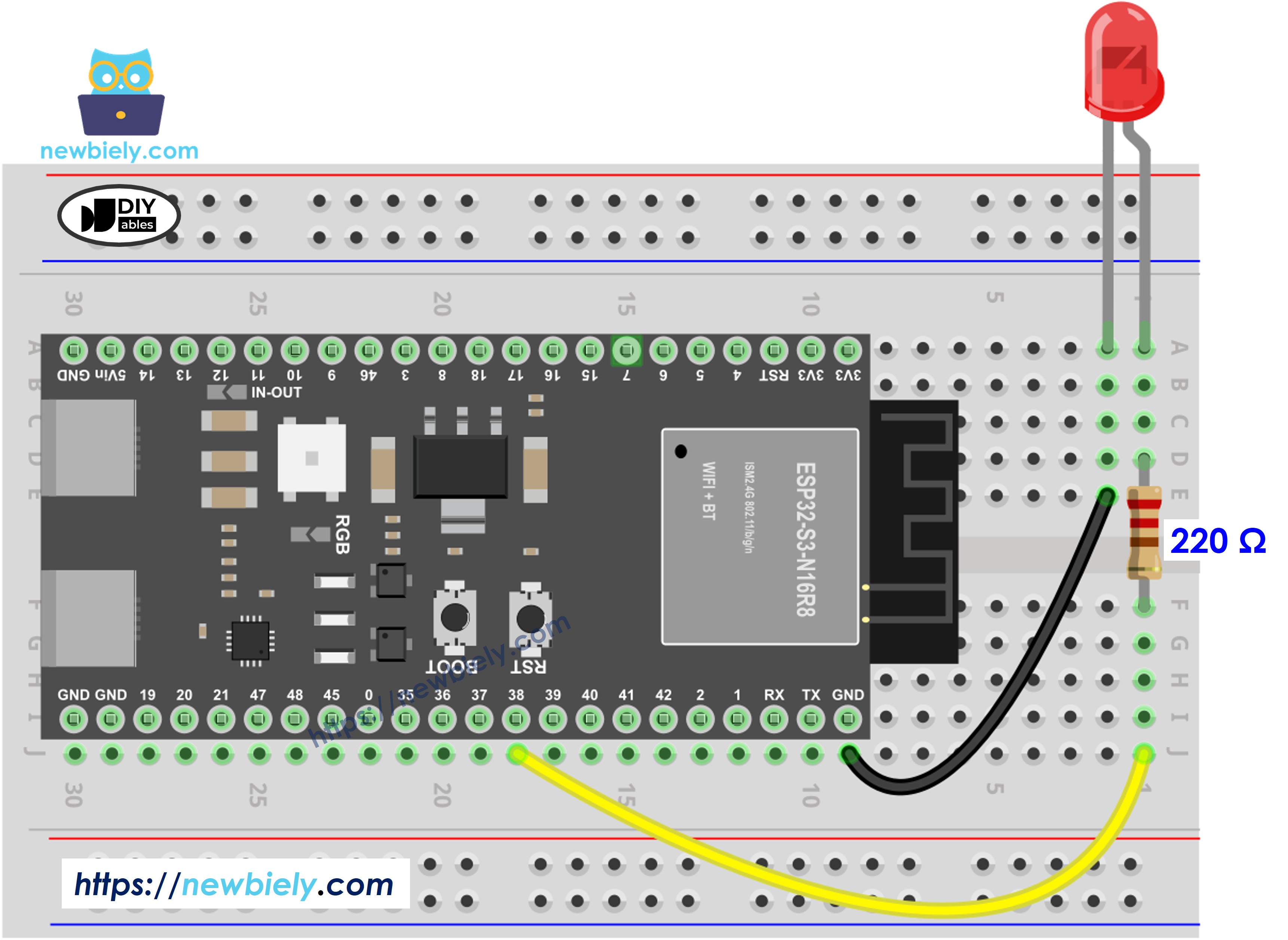
This image is created using Fritzing. Click to enlarge image
| LED Pin | Component | ESP32 S3 Pin |
|---|---|---|
| Anode (+) | 220Ω Resistor | GPIO38 |
| Cathode (-) | Direct Wire | GND |
How To Program
Controlling an LED with the ESP32 S3 requires just two Arduino functions: pinMode() to configure the pin as a digital output, and digitalWrite() to set it HIGH or LOW. The following snippets show each step individually before the complete sketch ties them together.
- Configure an ESP32 S3's pin to the digital output mode by using pinMode() function. For example, pin GPIO38:
ESP32 S3 Code
Detailed Instructions
- New to ESP32 S3? Complete our Getting Started with ESP32 S3 guide first.
- Wire the Circuit: Connect the components according to the wiring diagram above
- Connect Board: Plug the ESP32 S3 into your computer using a USB Type-C cable
- Open Arduino IDE: Launch the Arduino IDE on your computer
- Select Board: Choose ESP32 S3 and its corresponding COM port
- Copy Code: Copy the code below and paste it into Arduino IDE
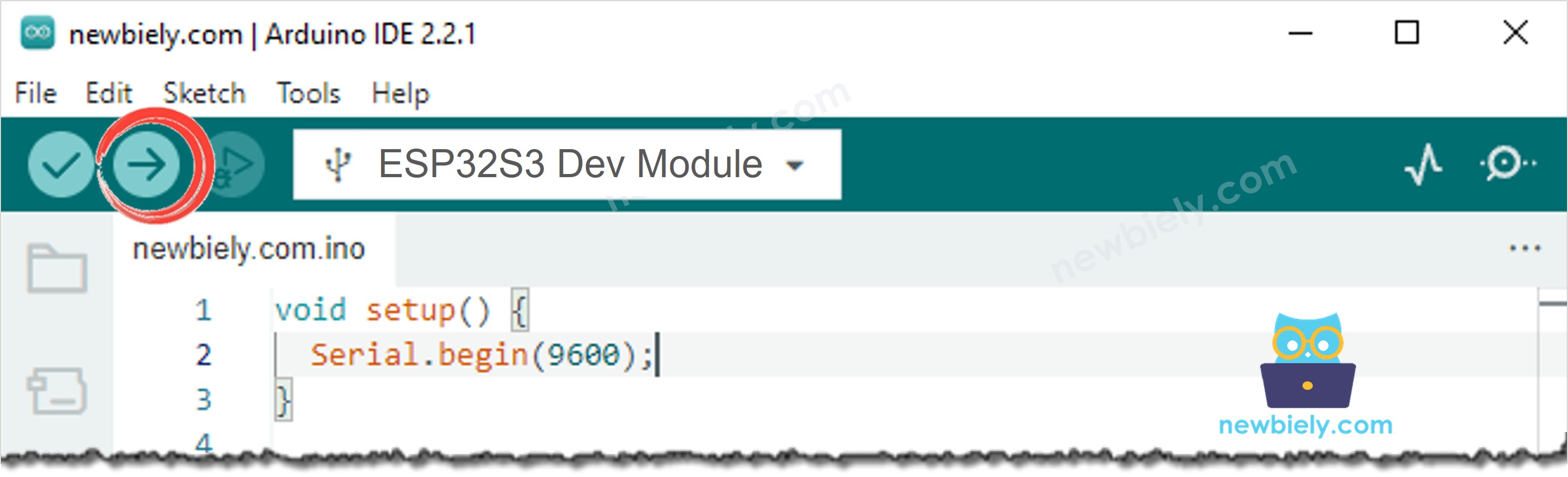
- Upload Code: Click the Upload button in Arduino IDE to compile and upload
- Observe Results: Watch the LED blink on and off once per second
- Pro Tip: Try changing the delay values to make the LED blink faster or slower—experiment with 100, 1000, or 2000 milliseconds!
Line-by-line Code Explanation
The above ESP32 S3 code contains line-by-line explanation. Please read the comments in the code!
※ NOTE THAT:
The above code uses the delay() function. This function blocks ESP32 S3 from doing other tasks. To avoid blocking ESP32 S3, see ESP32 S3 blink without delay
Application and Project Ideas
LED control is a gateway skill that applies directly to a wide variety of real-world ESP32 S3 projects.
- Status Indicator: Create visual alerts for temperature, humidity, or sensor thresholds using the ESP32 S3's analog inputs.
- Smart Home Lighting: Build a WiFi-controlled LED system that leverages the ESP32 S3's built-in wireless capabilities.
- Notification System: Flash an LED whenever the ESP32 S3 receives an IoT event, email alert, or MQTT message.
- Security Alarm: Design a motion-activated LED warning system triggered by a PIR sensor connected to the ESP32 S3.
- Traffic Light Controller: Simulate a traffic light by sequencing red, yellow, and green LEDs from separate GPIO pins.
- Visual Timer: Create a countdown timer with distinctive blinking patterns to indicate elapsed time.
Video Tutorial
Watch the step-by-step video walkthrough for this ESP32 S3 project below.
Challenge Yourself
Once your LED is blinking reliably on the ESP32 S3, push your skills further with these progressively challenging exercises.
- Beginner: Change the blink speed to flash 3 times per second instead of once per second.
- Beginner: Create an SOS pattern in Morse code (3 short, 3 long, 3 short blinks).
- Intermediate: Connect 3 LEDs and make them blink in sequence like a traffic light.
- Intermediate: Use the Serial Monitor to control LED on/off with keyboard commands sent to the ESP32 S3.
- Advanced: Implement LED brightness control using PWM and fade effects on the ESP32 S3.