
ESP32 S3 - DRV8825 Stepper Motor Driver
The ESP32 S3 pairs naturally with the DRV8825 stepper motor driver to deliver precise, programmable motion control using just two GPIO pins. This tutorial guides you from first wiring to running code, so you can have a NEMA 17 stepper motor stepping back and forth within minutes.
What you'll build:
- A DRV8825 stepper motor driver wired to your ESP32 S3 board
- A NEMA 17 stepper motor rotating forward and backward under AccelStepper control
- A safe power setup with a dedicated 12 V supply for the motor
- A foundation for 3D printers, CNC machines, and precision robotics projects
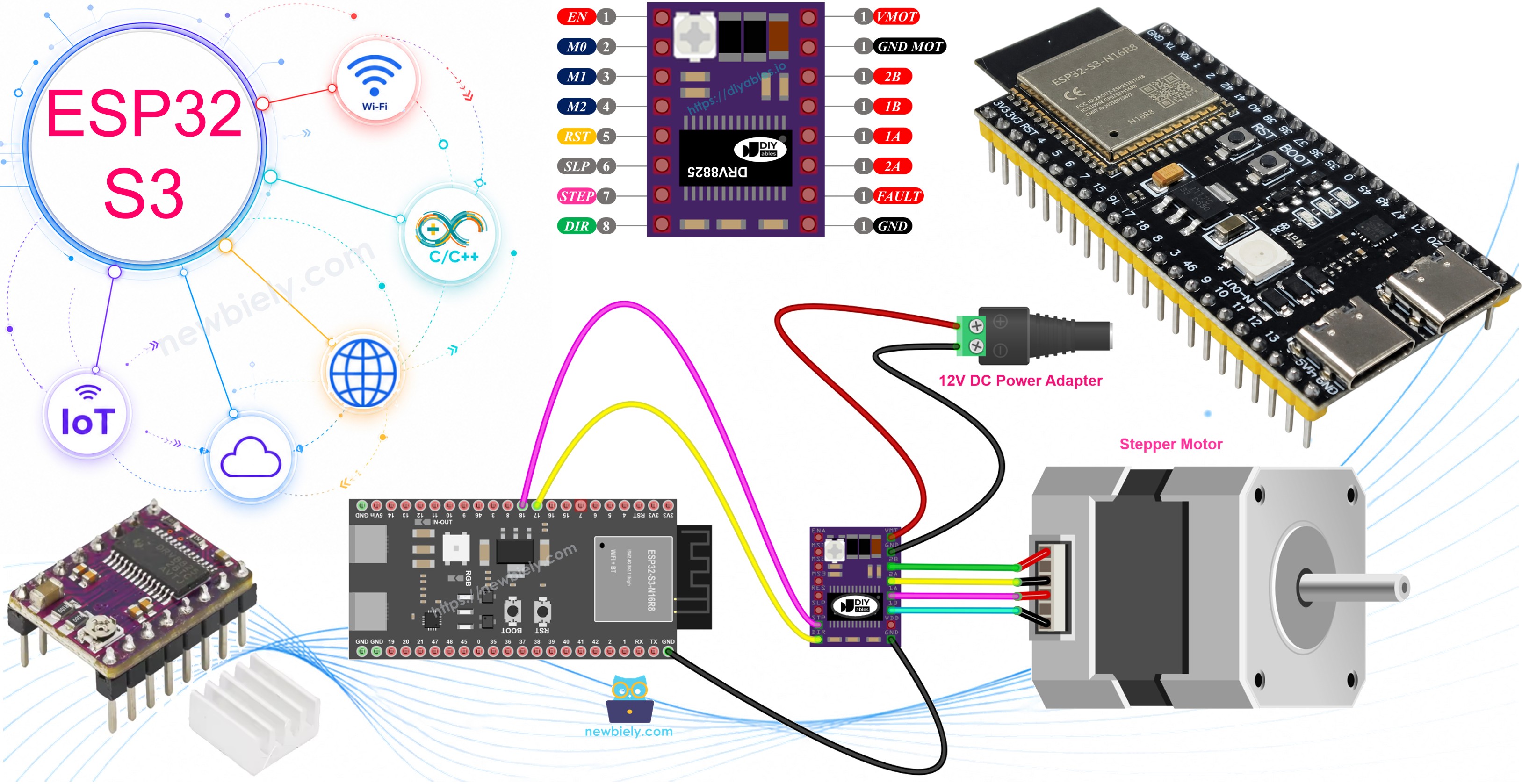
Hardware Preparation
Or you can buy the following kits:
| 1 | × | DIYables ESP32 S3 Starter Kit (ESP32 S3 included) | |
| 1 | × | DIYables Sensor Kit (18 sensors/displays) |
Additionally, some of these links are for products from our own brand, DIYables .
Overview of DRV8825 Stepper Motor Driver
The DRV8825 is a high-performance bipolar stepper motor driver that converts simple step-and-direction signals from a microcontroller into precisely timed coil currents. It supports microstepping down to 1/32 resolution, making motion noticeably smoother and quieter compared to full-step operation. An on-board adjustable potentiometer lets you dial in the current limit to match your motor's rating, and built-in over-current and thermal shutdown protection guard both the driver and motor during extended runs.
Key Specifications
- Voltage range: 8.2 V to 45 V motor power supply
- Current capacity: Up to 2.2 A per coil with proper cooling
- Microstepping: Supports full-step down to 1/32 step resolution
- Built-in protection: Over-current and thermal shutdown features
- Adjustable current limit: Potentiometer for easy adjustment
- Compact design: Perfect for 3D printers, CNC machines, and robotics
- Low pin count: Control with just 2 ESP32 S3 pins
- Built-in regulator: 3.3 V logic power derived from motor supply
- Beginner-friendly: Simple interface with step and direction control
To understand stepper motor concepts such as full-step, microstepping, unipolar stepper, and bipolar stepper, check out the ESP32 S3 - Stepper Motor guide.
DRV8825 Stepper Motor Driver Pinout
The DRV8825 module exposes 16 pins that cover motor outputs, power rails, and configuration inputs. The following numbered list describes each pin's role.
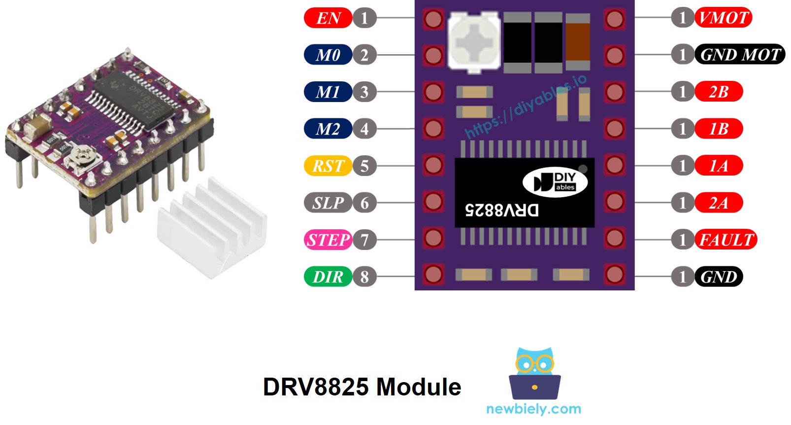
- VMOT — Motor power supply input (8.2 V to 45 V)
- GND (Motor) — Ground for motor power supply
- 2B, 2A — Output connections to stepper motor Coil B
- 1A, 1B — Output connections to stepper motor Coil A
- FAULT — Fault detection output (goes LOW on over-current or thermal shutdown)
- GND (Logic) — Ground reference for control signals (connect to ESP32 S3 GND)
- ENABLE — Active-LOW enable pin (LOW = motor enabled, HIGH = motor disabled)
- M0, M1, M2 — Microstepping resolution selector pins
- RESET — Active-LOW reset pin (LOW = reset driver)
- SLEEP — Active-LOW sleep mode pin (LOW = low-power sleep mode)
- STEP — Step input pin (rising edge advances motor one microstep)
- DIR — Direction control pin (sets rotation direction)
- Potentiometer — Adjustable current limit control
Pin grouping by function:
- Motor connections: 1A, 1B, 2A, 2B
- Motor control: DIR, STEP
- Driver configuration: ENABLE, M0, M1, M2, RESET, SLEEP
- Status output: FAULT
- Motor power: VMOT, GND (motor)
- Logic ground: GND (logic)
Important: Always connect the ESP32 S3 GND to the DRV8825 GND (logic) pin to establish a common ground reference. The DRV8825 powers its logic circuitry from the motor supply through its built-in 3.3 V regulator, so no separate logic supply is needed.
Microstep Configuration
The DRV8825 enables microstepping by electronically subdividing each full step into smaller increments, resulting in smoother motion, less vibration, and quieter operation at the cost of more step pulses per revolution.
Example microstep resolutions for NEMA 17 motor (1.8° step angle, 200 steps/revolution):
- Full-step mode: 200 steps per revolution
- Half-step mode: 400 steps per revolution
- Quarter-step mode (1/4): 800 steps per revolution
- Eighth-step mode (1/8): 1,600 steps per revolution
- Sixteenth-step mode (1/16): 3,200 steps per revolution
- Thirty-second-step mode (1/32): 6,400 steps per revolution
Benefits of higher microstepping:
- Smoother motor movement with less vibration
- Higher positioning accuracy
- Quieter operation
- More steps required per revolution (slower speed at same pulse rate)
Speed considerations:
- Higher microstepping requires more step pulses per revolution
- Motor speed depends on the ESP32 S3 pulse rate
- Faster pulse rates maintain speed with higher microstepping
- Maximum speed is limited by driver and microcontroller capabilities
DRV8825 Microstep Selection Pins
Configure microstepping resolution by setting the M0, M1, and M2 pins on the DRV8825 driver. All three pins have internal pull-down resistors and default to LOW, so leaving them unconnected puts the driver into full-step mode.
Microstepping selection table:
| M0 Pin | M1 Pin | M2 Pin | Microstep Resolution |
|---|---|---|---|
| Low | Low | Low | Full step |
| High | Low | Low | Half step |
| Low | High | Low | 1/4 step |
| High | High | Low | 1/8 step |
| Low | Low | High | 1/16 step |
| High | Low | High | 1/32 step |
| Low | High | High | 1/32 step |
| High | High | High | 1/32 step |
How it Works
The DRV8825 translates straightforward digital signals from the ESP32 S3 into the carefully timed coil currents that a bipolar stepper motor needs to rotate. On each rising edge of the STEP pin the driver advances the motor one microstep (or full step, depending on M0–M2 configuration), while the DIR pin selects clockwise or counter-clockwise rotation. Only two ESP32 S3 GPIO pins are needed for the most common use case, and additional pins such as ENABLE, RESET, and SLEEP can be left unconnected for defaults or tied to GPIO pins when dynamic control is required.
Basic operation:
- STEP Pin: Each rising edge moves the motor one microstep (or full step depending on configuration)
- DIR Pin: Controls rotation direction (HIGH or LOW)
- Driver logic: Converts step and direction signals into proper coil currents
- Motor outputs: Pins 1A, 1B, 2A, 2B deliver controlled current to motor coils
Optional pin configurations:
You can configure additional DRV8825 pins (ENABLE, M0, M1, M2, RESET, SLEEP) in three ways:
- Leave unconnected: Driver uses default settings (full-step, enabled)
- Connect to GND or VCC: Fixed configuration (e.g., always enabled or a specific microstep mode)
- Connect to ESP32 S3 pins: Dynamic control through your code
Wiring Diagram
Connect your ESP32 S3, DRV8825 stepper motor driver, and NEMA 17 stepper motor following this wiring diagram. The motor coil wires connect to the 1A/1B and 2A/2B outputs on the driver, while the STEP and DIR signals come from the ESP32 S3 GPIO pins.
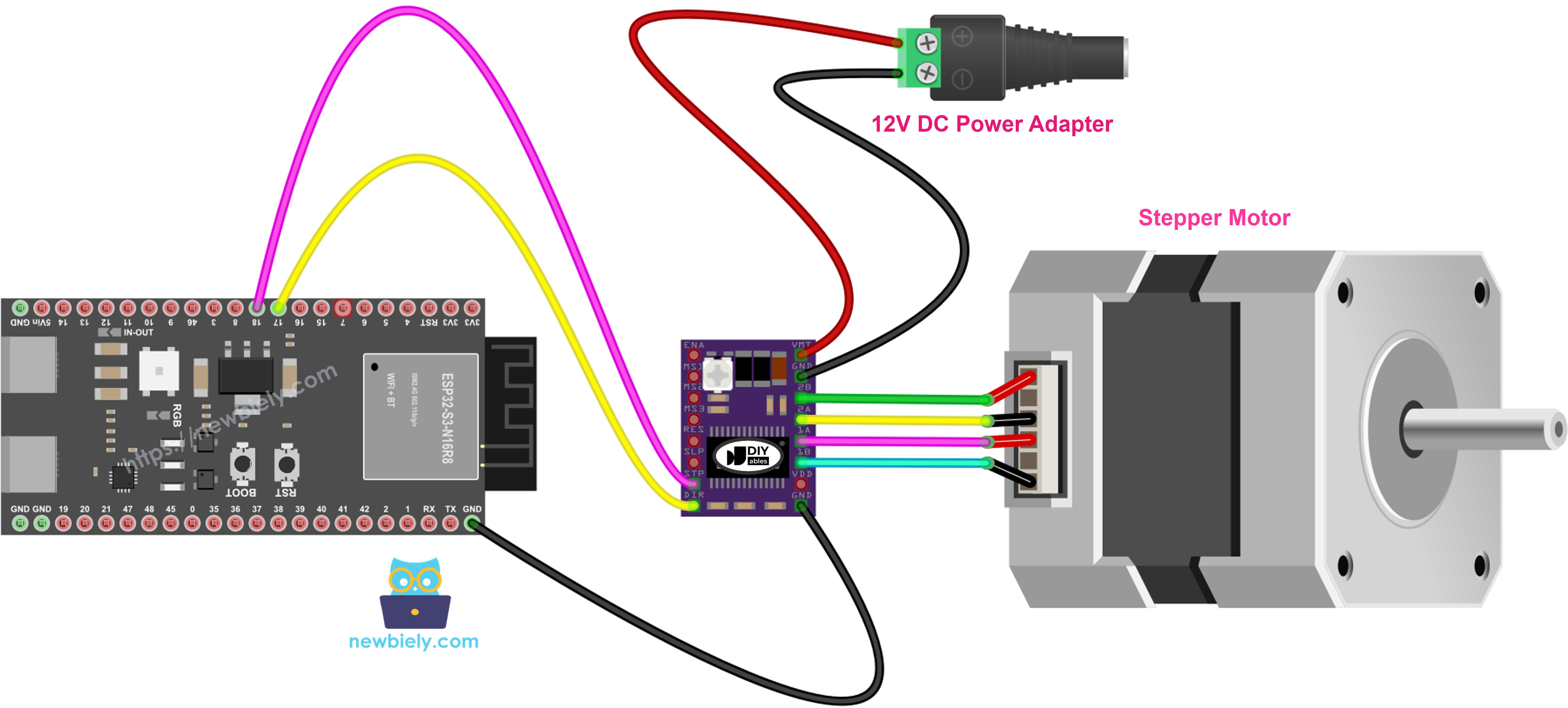
This image is created using Fritzing. Click to enlarge image
Safety Notes
Never connect or disconnect the stepper motor while the power supply is live — doing so can generate voltage spikes that permanently damage the DRV8825. Always verify that the motor power supply voltage matches your stepper motor's specifications (typically 12 V for NEMA 17 motors) before switching on, and confirm that the ESP32 S3 GND is shared with the DRV8825 logic GND before sending any step pulses.
| DRV8825 Pin | Connection | Notes |
|---|---|---|
| VMOT | 12V Power Supply (+) | Motor power input |
| GND (Motor) | 12V Power Supply (-) | Motor power ground |
| 1A | Stepper Motor Coil A Wire 1 | Coil A connection |
| 1B | Stepper Motor Coil A Wire 2 | Coil A connection |
| 2A | Stepper Motor Coil B Wire 1 | Coil B connection |
| 2B | Stepper Motor Coil B Wire 2 | Coil B connection |
| STEP | ESP32 S3 Pin D10 | Step control signal |
| DIR | ESP32 S3 Pin D9 | Direction control signal |
| GND (Logic) | ESP32 S3 GND | Common ground reference |
| ENABLE | Not connected | Default enabled |
| M0 | Not connected | Full-step mode |
| M1 | Not connected | Full-step mode |
| M2 | Not connected | Full-step mode |
| RESET | Not connected | Normal operation |
| SLEEP | Not connected | Normal operation |
This basic configuration runs the stepper motor in full-step mode with default settings.
ESP32 S3 Code
The following code demonstrates how to control a stepper motor with the ESP32 S3 and DRV8825 driver using the AccelStepper library. It configures the driver interface, sets a maximum speed and acceleration, then commands the motor to rotate 200 steps forward and 200 steps backward in a continuous loop — reading the inline comments will give you a line-by-line breakdown of how each section works.
Detailed Instructions
- New to ESP32 S3? Complete our Getting Started with ESP32 S3 guide first.
- Set up the Arduino IDE for ESP32 S3 by following the ESP32 S3 software installation guide.
- Wire the DRV8825, stepper motor, and 12 V power supply to the ESP32 S3 according to the wiring diagram above.
- Connect the ESP32 S3 board to your computer with a USB Type-C cable.
- Open the Arduino IDE on your computer.
- Select the ESP32 S3 board and its corresponding COM port under Tools.
- Open Library Manager by clicking the Libraries icon on the left sidebar.
- Type "AccelStepper" in the search box, find the library by Mike McCauley, and click Install.
- Search for AccelStepper created by Mike McCauley
- Copy the code above and paste it into a new Arduino IDE sketch.
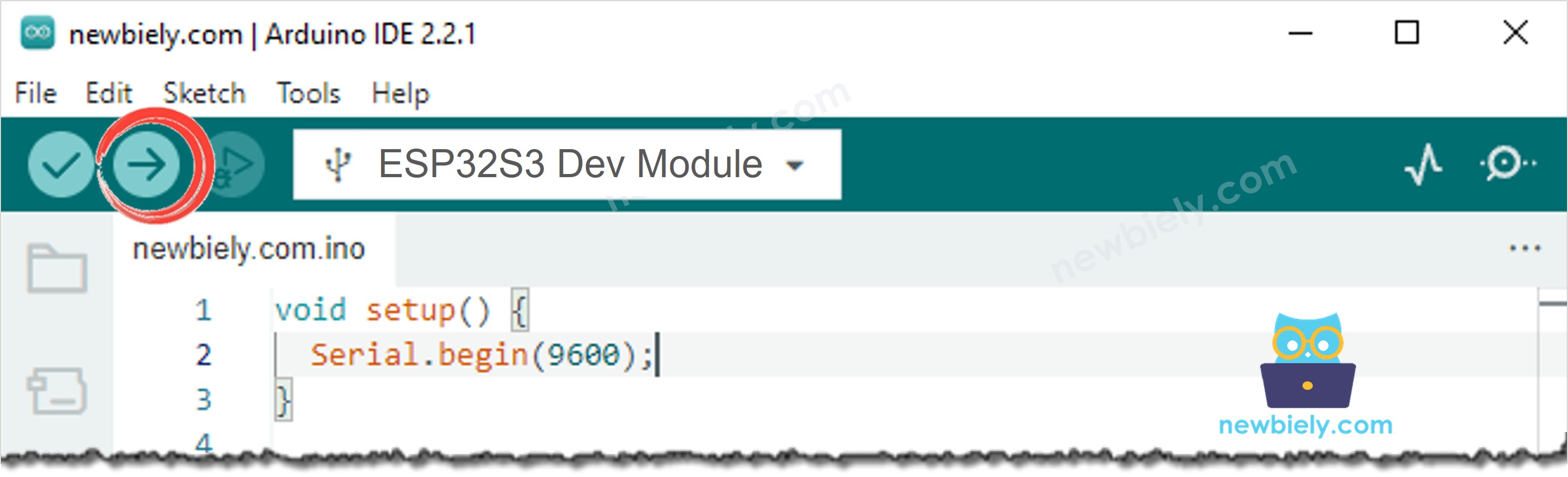
- Click the Upload button to compile and transfer the code to the ESP32 S3.
- Observe the stepper motor rotating back and forth continuously.
- Pro Tip: For smoother, quieter motor operation, enable microstepping by connecting M0, M1, and M2 to ESP32 S3 GPIO pins and setting them HIGH or LOW in your code to select the desired resolution.
Note: Full-step mode produces visible stepping motion. Enable microstepping for smoother, quieter operation by configuring the M0, M1, and M2 pins.
Serial Monitor Output
After uploading the code, open the Serial Monitor at 115200 baud rate to see the motor status. The output below reflects a typical session recorded in 2026.
Applications and Project Ideas
The ESP32 S3 paired with the DRV8825 stepper motor driver opens up a wide range of precision motion control projects, from desktop prototypes to production-grade automation systems:
- 3D Printer: Build a custom 3D printer with precise X, Y, and Z axis control driven by multiple DRV8825 drivers.
- CNC Machine: Create a mini CNC router or engraver for PCBs and small mechanical parts.
- Camera Slider: Design an automated camera slider for smooth, motorized time-lapse photography.
- Robotic Arm: Build a multi-axis robotic arm with accurate joint positioning for pick-and-place tasks.
- Automated Curtain Opener: Make smart curtains that open and close on a schedule or via a WiFi command.
- Pan-Tilt Camera Mount: Create a motorized two-axis camera mount for video surveillance or remote photography.
- Automatic Pet Feeder: Design a timed pet feeder with portion control using stepper-driven gate mechanism.
- Solar Panel Tracker: Build a sun-tracking system that rotates a solar panel for maximum energy harvest.
Watch the step-by-step video walkthrough for this ESP32 S3 project below.
Challenge Yourself
Once your stepper motor is running reliably with the ESP32 S3 and DRV8825, try these challenges to deepen your understanding of motor control and embedded programming:
- Beginner: Add a potentiometer to control motor speed in real time by reading an analog input and mapping it to the AccelStepper max speed.
- Beginner: Add LED indicators to show motor direction — a green LED for forward and a red LED for backward.
- Intermediate: Enable microstepping by wiring M0, M1, and M2 to ESP32 S3 GPIO pins and switch between resolutions in your code.
- Intermediate: Add push buttons to start and stop motor movement, and a third button to toggle direction.
- Advanced: Create a position control system that accepts Serial Monitor commands to move the motor to specific step positions.
- Advanced: Build a two-axis motion control system using two DRV8825 drivers and stepper motors for X-Y plotting or laser engraving.
- Advanced: Implement smooth acceleration and deceleration profiles for fast, precise moves that start and stop without losing steps.