
ESP32 S3 - Rotary Encoder
Learn how to use a rotary encoder with your ESP32 S3 to detect rotation direction and position. This tutorial walks you through wiring, basic polling code, and a more efficient interrupt-based approach — giving you everything you need to integrate a rotary encoder into your ESP32 S3 projects.
What you'll build:
- A circuit connecting a rotary encoder to the ESP32 S3
- A sketch that detects clockwise and counterclockwise rotation
- An interrupt-driven version for improved performance and reliability
- A foundation for real-world applications such as menus, motor control, and volume adjustment
Hardware Preparation
Or you can buy the following kits:
| 1 | × | DIYables ESP32 S3 Starter Kit (ESP32 S3 included) | |
| 1 | × | DIYables Sensor Kit (18 sensors/displays) |
Additionally, some of these links are for products from our own brand, DIYables .
Overview of Rotary Encoder
A rotary encoder is a position sensor that converts rotational movement into electrical signals, allowing a microcontroller like the ESP32 S3 to determine both the direction and the amount of rotation. Unlike a potentiometer, a rotary encoder can spin continuously without hitting a mechanical stop, making it ideal for navigation menus, motor speed control, and other applications where unlimited rotation is needed.
This tutorial focuses on incremental rotary encoders — the most common and beginner-friendly type for ESP32 S3 projects.
Key Specifications
Incremental encoders generate two digital pulse signals (A and B) that are 90 degrees out of phase. By comparing which signal changes first, the ESP32 S3 can determine whether the knob was turned clockwise or counterclockwise. Most modules also include an integrated push-button switch, activated by pressing down on the knob. The encoder can rotate continuously in either direction with no end stops, and the onboard module typically accepts a supply voltage of 3.3V to 5V.
Rotary Encoder Module Pinout
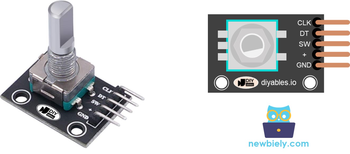
The rotary encoder module exposes five pins that connect to your ESP32 S3:
- CLK pin (Output A): Primary pulse output that signals rotation — outputs one complete LOW-to-HIGH-to-LOW cycle per detent click
- DT pin (Output B): Secondary pulse output that lags CLK by 90 degrees, used to determine rotation direction
- SW pin: Push-button connection — normally open, reads HIGH when idle and LOW when the knob is pressed (requires a pull-up resistor)
- VCC pin (+): Power supply — connect to 3.3V on the ESP32 S3
- GND pin: Ground reference — connect to GND
Rotary Encoder vs Potentiometer
You might be tempted to confuse a rotary encoder with a potentiometer, but they serve fundamentally different purposes. A potentiometer outputs an analog voltage proportional to a fixed rotation range (typically 270°), making it best for reading an absolute position. A rotary encoder outputs digital pulses over unlimited rotation, making it ideal for tracking relative movement — how much and in which direction the knob has turned.
Key Differences
Rotary encoders rotate continuously 360° while potentiometers have a fixed mechanical limit. Encoders output digital pulses; potentiometers output analog voltage. Encoders track relative movement; potentiometers track absolute position. For projects on the ESP32 S3 that need menu navigation, motor speed adjustment, or any knob that keeps spinning, a rotary encoder is the right choice.
How Rotary Encoder Works
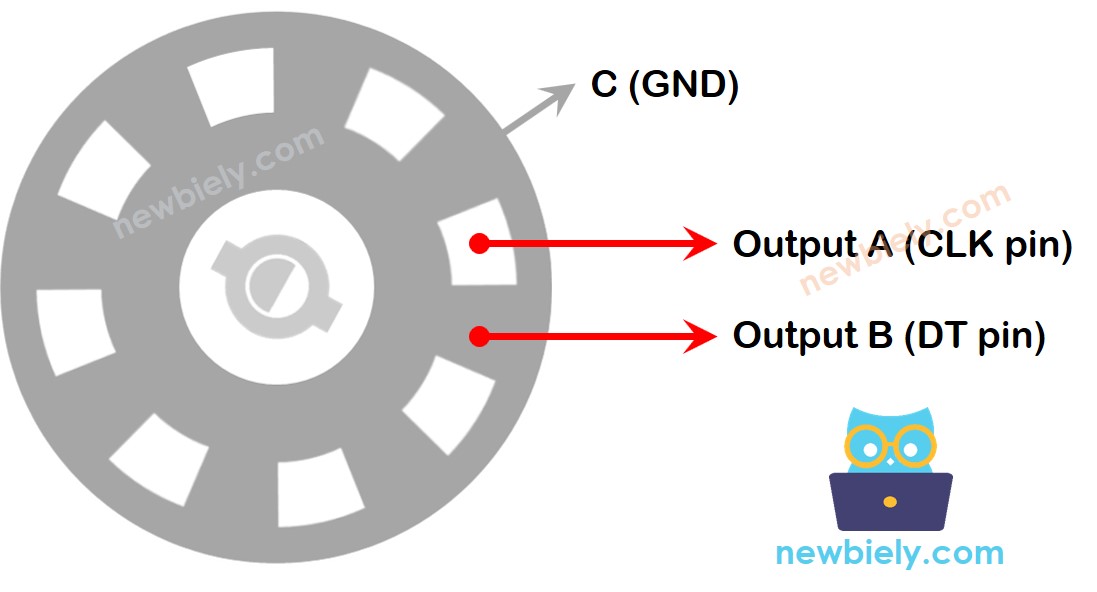
Inside the encoder, a slotted disc connects to a common ground (pin C). As the knob rotates, pins A and B alternately make contact with the common ground, generating two pulse trains that are 90 degrees out of phase — a technique called quadrature encoding.
Internal mechanism:
- A slotted disc inside connects to pin C (common ground)
- Pins A and B make contact with common ground as the knob rotates
- The order of contact between A and B determines rotation direction
- Two pulse signals 90 degrees out of phase are produced (quadrature encoding)
Detecting rotation direction:
- Clockwise rotation: Pin A contacts ground before pin B
- Counterclockwise rotation: Pin B contacts ground before pin A
- The ESP32 S3 reads pin B's state the moment pin A transitions, and uses that to determine direction
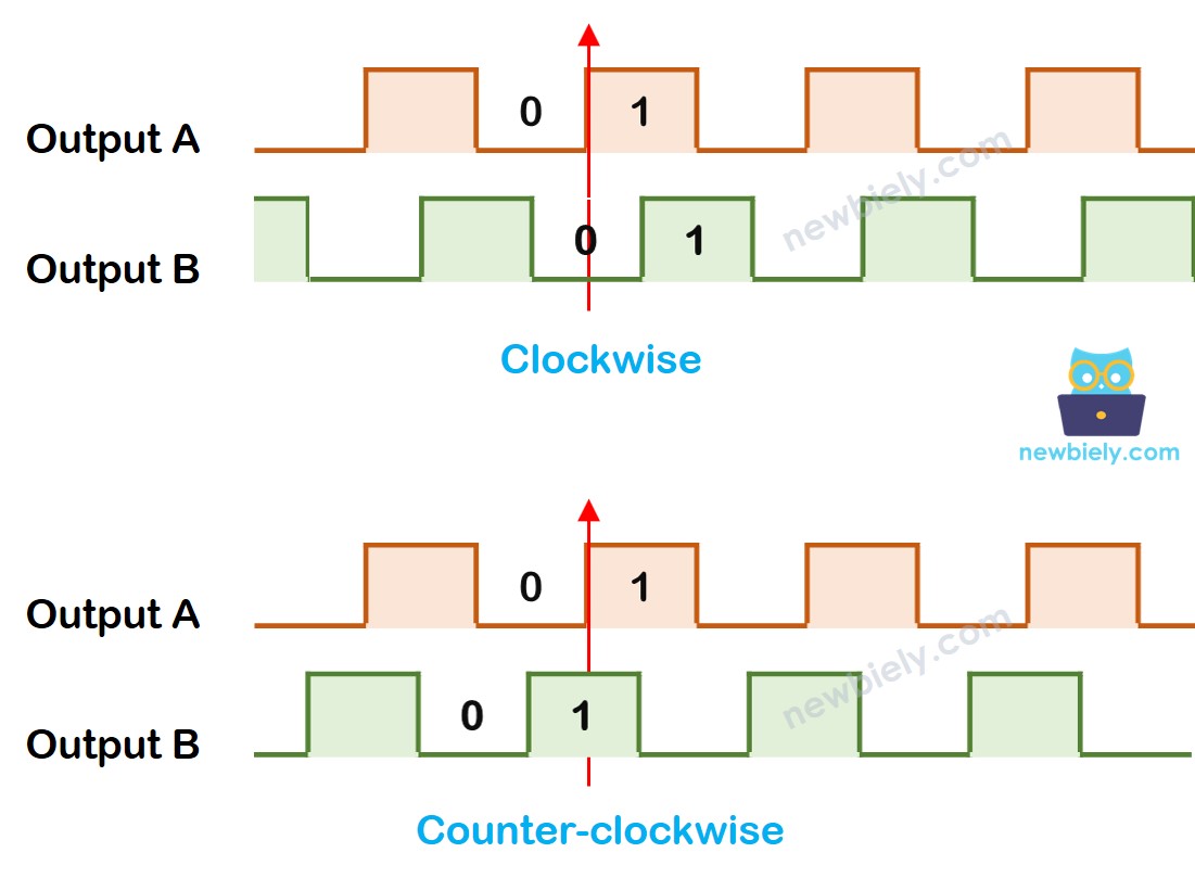
Direction detection logic:
When pin A changes from LOW to HIGH:
- If pin B is HIGH: The knob was turned counterclockwise
- If pin B is LOW: The knob was turned clockwise
※ NOTE THAT:
Pins A and B connect to CLK and DT pins. Depending on the manufacturer, the order may vary. The code below is tested with DIYables rotary encoders.
How To Program For Rotary Encoder
The ESP32 S3 reads the rotary encoder by monitoring the CLK pin for state changes. When CLK transitions from LOW to HIGH, the sketch immediately samples the DT pin:
- The ESP32 S3 monitors the CLK pin continuously
- When CLK rises from LOW to HIGH, the DT pin is read immediately
- If DT is HIGH: Counterclockwise rotation → increment the counter by 1
- If DT is LOW: Clockwise rotation → decrement the counter by 1
- This method reliably tracks both direction and cumulative rotation amount
Wiring Diagram
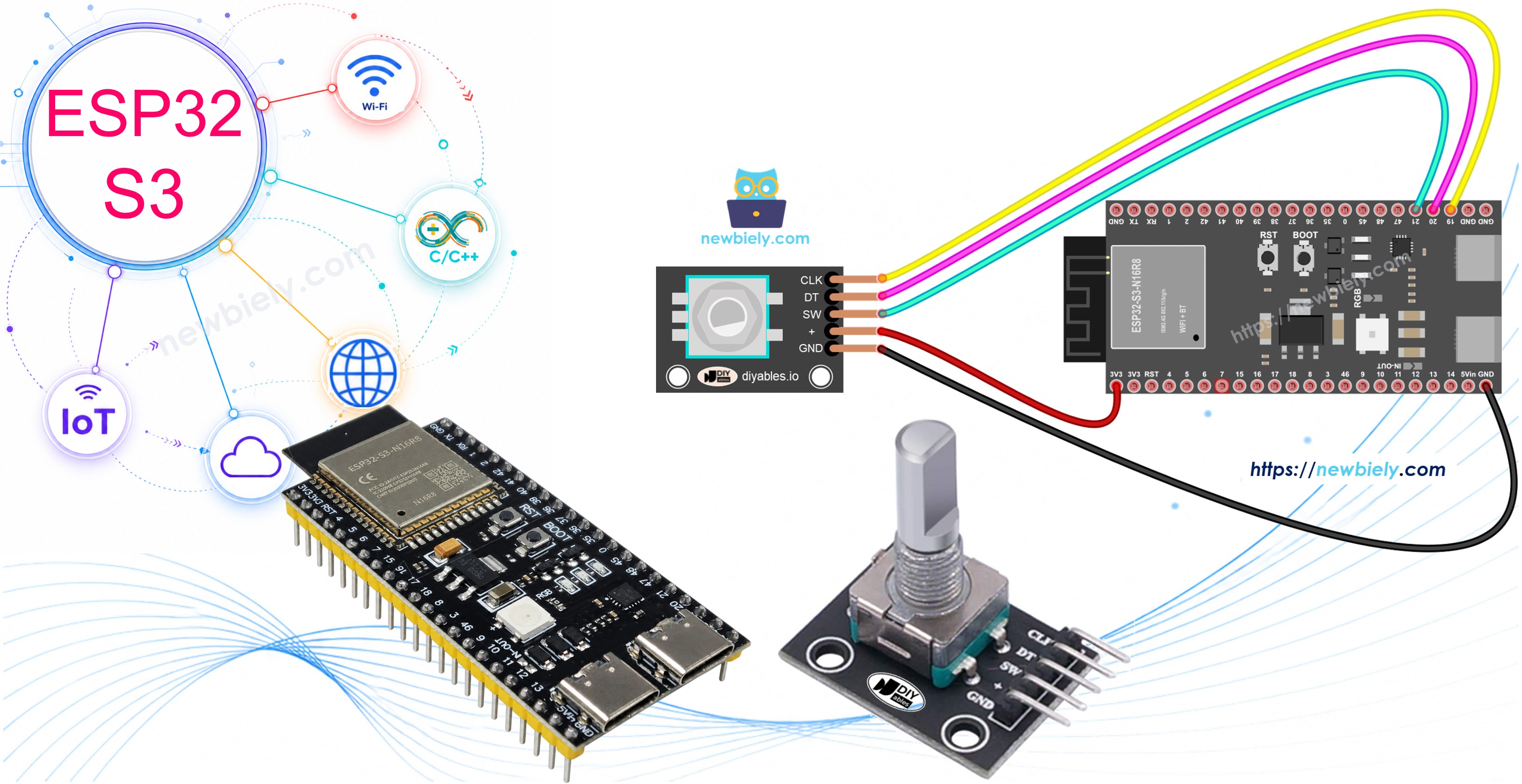
Connect the rotary encoder to your ESP32 S3 as shown in the diagram below. Use short jumper wires to keep signal lines clean and avoid noise that could cause false counts.
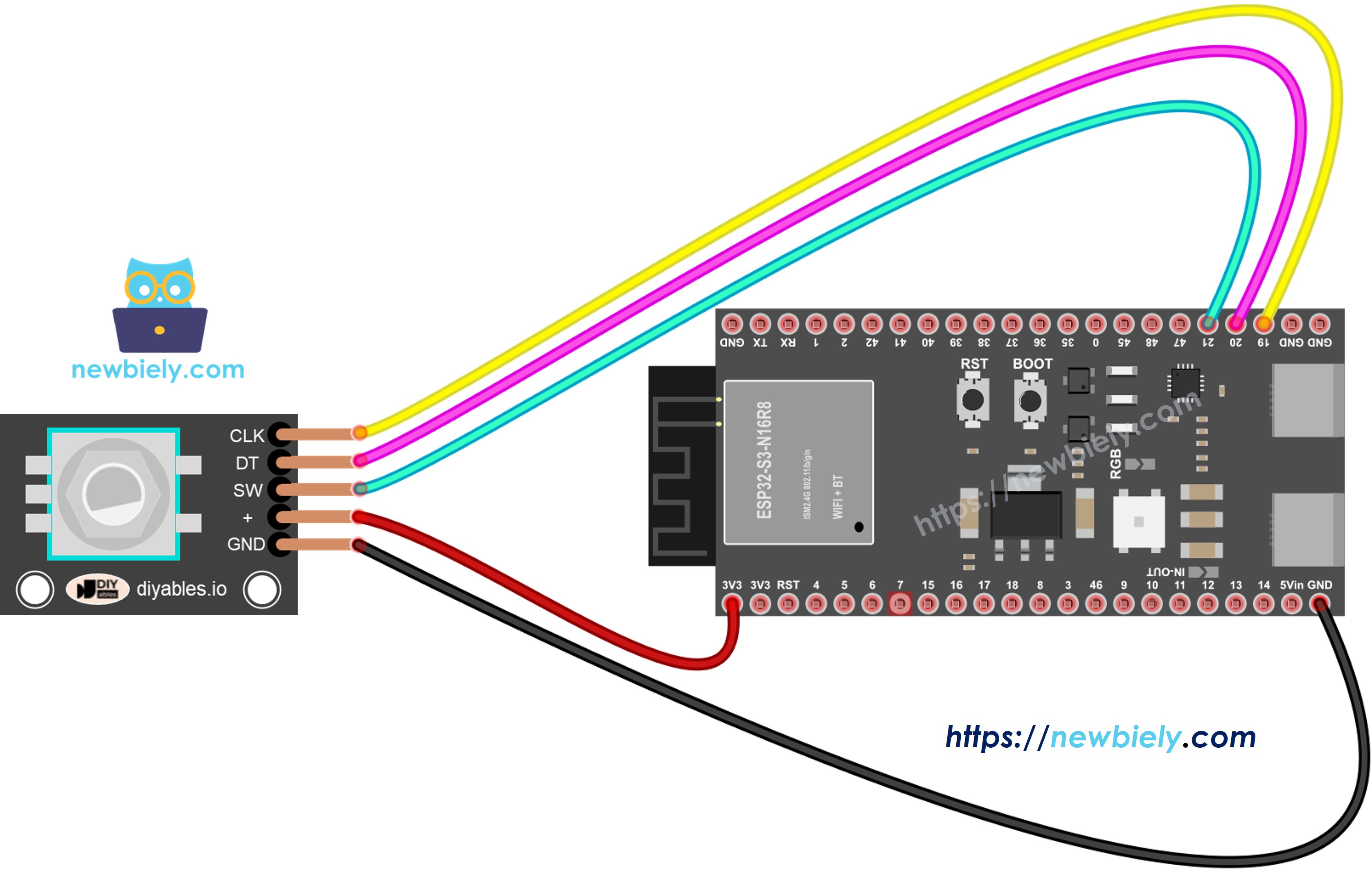
This image is created using Fritzing. Click to enlarge image
Safety Notes
Always connect VCC to the 3.3V pin on the ESP32 S3 rather than 5V to stay within the board's GPIO voltage tolerance. The SW pin requires a pull-up resistor — most rotary encoder modules include one onboard, but verify this on your module before skipping an external resistor.
| Rotary Encoder Pin | ESP32 S3 Pin |
|---|---|
| CLK | GPIO19 |
| DT | GPIO20 |
| SW | GPIO21 |
| VCC | 3.3V |
| GND | GND |
ESP32 S3 Code – Rotary Encoder
The following sketch demonstrates basic rotary encoder reading on the ESP32 S3 using a polling approach. It detects the rotation direction, maintains a running counter of detent clicks, and reports button presses — all printed to the Serial Monitor. The ezButton library handles switch debouncing automatically, making button detection reliable without extra boilerplate code.
Note: This code uses the ezButton library to simplify button debouncing for reliable button press detection.
Detailed Instructions
- New to ESP32 S3? Complete our Getting Started with ESP32 S3 guide first.
- Install Library: Add the ezButton library through Arduino IDE Library Manager
- Open Code: Copy the code above and paste it into Arduino IDE
- Upload: Click the Upload button to transfer the sketch to your ESP32 S3
- Test Rotation: Turn the encoder knob clockwise several clicks, then counterclockwise
- Test Button: Press down on the encoder knob
- View Results: Open Serial Monitor (115200 baud) to see rotation direction and count
- Pro Tip: Each tactile "click" you feel when turning the knob is called a detent — the encoder produces exactly one complete pulse cycle per detent, so your click count and the counter value will always match
Serial Monitor Output:
Code Explanation
Review the detailed line-by-line comments in the code above to understand how each section works.
ESP32 S3 Code – Rotary Encoder with Interrupt
The polling approach in the previous sketch works well for simple projects, but it consumes ESP32 S3 processing cycles even when the knob is not moving — and can miss pulses if other code runs too slowly. Interrupts solve both problems by letting the hardware notify the ESP32 S3 the instant a CLK transition occurs, freeing the main loop for other tasks.
The following sketch uses a hardware interrupt on the CLK pin to read the rotary encoder efficiently. The direction logic is identical to the polling version, but the encoder state is captured inside an interrupt service routine (ISR) so no pulses are ever missed.
When you turn the knob, the Serial Monitor displays the same rotation information as the previous example, but with improved performance and reliability on the ESP32 S3.
※ NOTE THAT:
- One interrupt is enough: Many tutorials attach interrupts to both CLK and DT, but a single interrupt on CLK is sufficient and uses fewer resources
- Use volatile keyword: Always declare variables that are modified inside an ISR as volatile so the compiler does not optimize them away
- Keep ISRs short: Avoid calling Serial.print() or Serial.println() inside an interrupt — set a flag or update a counter, then handle output in the main loop
- Fast execution: The shorter and faster your ISR, the more reliable encoder reading will be under load
ESP32 S3 Rotary Encoder Applications
Rotary encoders pair naturally with the ESP32 S3's processing power and connectivity, enabling a wide range of interactive and control-oriented projects.
- Servo motor control: Rotate the encoder to set servo position with precise, click-by-click angular control
- LED brightness dimmer: Map the encoder counter to a PWM duty cycle for smooth, stepless brightness adjustment
- Stepper motor speed control: Regulate stepper speed in real time for robotics and CNC applications
- Digital volume control: Adjust audio output level in home automation or Bluetooth speaker projects
- OLED menu navigation: Scroll through menu items by turning the knob and select with a button press
- Smart thermostat: Set target temperature with the encoder and display the value on a screen
- RGB LED color picker: Map encoder position to hue, cycling through the full color spectrum
Video Tutorial
Watch the step-by-step video walkthrough for this ESP32 S3 project below.
Challenge Yourself
Now that you have a working rotary encoder on the ESP32 S3, try these exercises to deepen your understanding and push the project further.
- Beginner: Wire up an LED that blinks once each time the encoder button is pressed
- Beginner: Display the current counter value on a 4-digit 7-segment display instead of the Serial Monitor
- Intermediate: Use the encoder counter to control a servo motor angle — map the counter range to 0–180 degrees
- Intermediate: Build a PWM-based LED brightness dimmer that responds in real time to encoder rotation
- Advanced: Create a multi-level menu system on an OLED or LCD display, with the encoder for scrolling and the button for selection