
ESP32 S3 - LED - Blink Without Delay

The simplest way to blink an LED is with the delay() function, but this blocks the ESP32 S3 from doing anything else during the wait. This tutorial teaches you a better approach using the millis() function, which lets the ESP32 S3 blink an LED while staying free to handle other tasks simultaneously.

What you'll build:

  1. An ESP32 S3 circuit with an LED and a button wired to the board
  2. A non-blocking LED blink using millis() instead of delay()
  3. A button-state monitor that works correctly even while the LED is blinking
  4. A multi-task example blinking two LEDs at different intervals alongside button detection
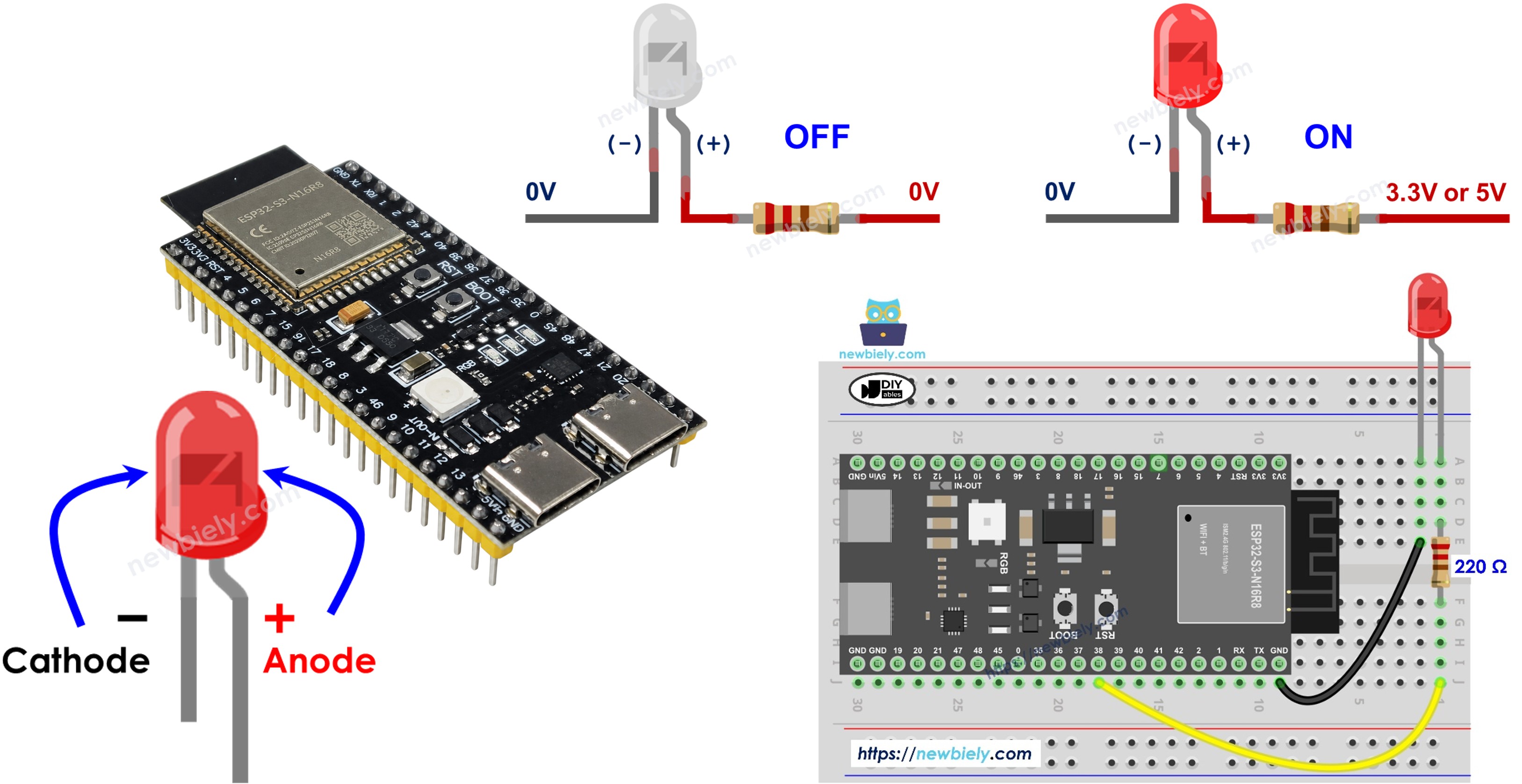
ESP32 S3 - LED - Blink Without Delay

We will run through three examples and compare the difference between them.

This method can be applied to let ESP32 S3 do several tasks at the same time. Blinking LED is just an example.

Hardware Preparation

1×ESP32 S3 WROOM N16R8
1×USB Cable Type-A to Type-C (for USB-A PC)
1×USB Cable Type-C to Type-C (for USB-C PC)
1×LED Kit
1×LED (red)
1×LED Module
1×Alternatively, Button and LED Kit
1×220Ω Resistor
1×Breadboard-mount Button with Cap
1×Breadboard-mount Button Kit
1×Panel-mount Push Button
1×Push Button Module
1×Breadboard
1×Jumper Wires
1×Optionally, DC Power Jack

Or you can buy the following kits:

1×DIYables Sensor Kit (18 sensors/displays)
Disclosure: Some of the links provided in this section are Amazon affiliate links. We may receive a commission for any purchases made through these links at no additional cost to you.
Additionally, some of these links are for products from our own brand, DIYables .

Buy Note: Use the LED Module for easier wiring. It includes an integrated resistor.

Overview of LED and Button

LEDs and buttons are the two most fundamental components for building interactive ESP32 S3 projects. The LED provides instant visual feedback from your program, while the button supplies digital input that the ESP32 S3 reads in real time. Combining them in a non-blocking sketch lets you observe how millis()-based timing keeps the ESP32 S3 responsive to input even while it is managing timed output.

Key Specifications

We have dedicated tutorials for each component with detailed pinouts, wiring instructions, and example code:

Wiring Diagram

Connect the LED and button to your ESP32 S3 by following the wiring diagram below. Make sure the LED is wired through a 220 ohm resistor and that the polarity is correct before powering the board.
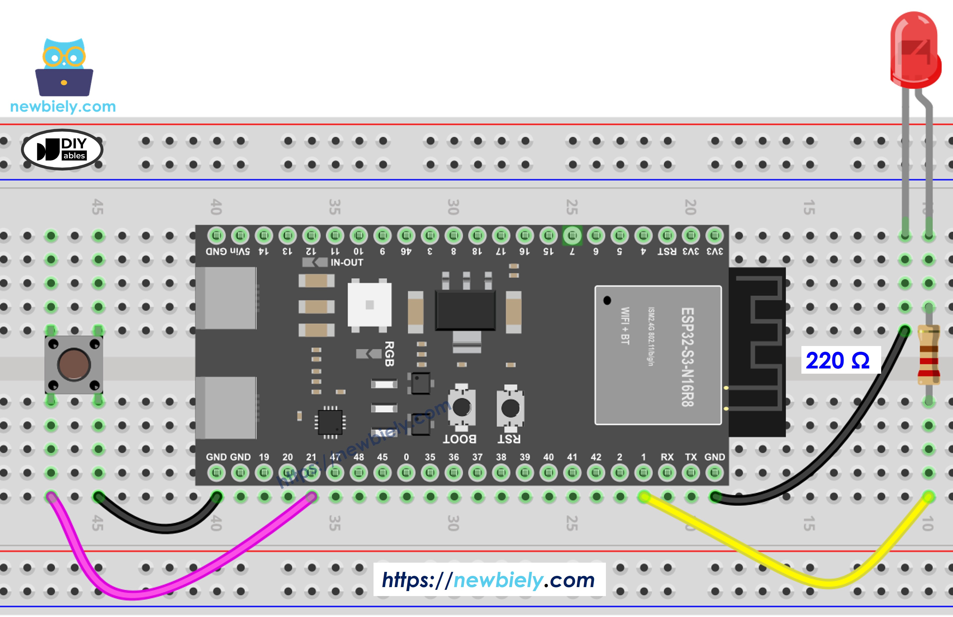
The wiring diagram between ESP32 S3 LED button

This image is created using Fritzing. Click to enlarge image

Safety Notes

Always place the 220 ohm resistor in series with the LED to limit current and protect both the LED and the ESP32 S3 GPIO pin from damage. The button connects one terminal to GND and the other to a GPIO pin; the sketch enables the internal pull-up resistor so no external resistor is needed for the button.

Component Pin ESP32 S3 Pin
LED Anode (long leg) D7
LED Cathode (short leg) 220Ω resistor to GND
Button One terminal D5
Button Other terminal GND

Let's compare the ESP32 S3 code that blinks LED with and without using delay() function

ESP32 S3 Code - With Delay

The following code blinks an LED using the blocking delay() function and also reads a button state on every loop iteration. While simple to write, this approach has a significant limitation: the ESP32 S3 cannot process button presses or any other input during the delay period, causing missed events.

/* * This ESP32 S3 code was developed by newbiely.com * * This ESP32 S3 code is made available for public use without any restriction * * For comprehensive instructions and wiring diagrams, please visit: * https://newbiely.com/tutorials/esp32-s3/esp32-s3-led-blink-without-delay */ #define LED_PIN 7 // The ESP32 S3 pin GPIO7 connected to LED #define BUTTON_PIN 5 // The ESP32 S3 pin GPIO5 connected to button #define BLINK_INTERVAL 1000 // interval at which to blink LED (milliseconds) // Variables will change: int ledState = LOW; // ledState used to set the LED int previousButtonState = LOW; // will store last time button was updated void setup() { Serial.begin(9600); // set the digital pin as output: pinMode(LED_PIN, OUTPUT); // set the digital pin as an input: pinMode(BUTTON_PIN, INPUT_PULLUP); } void loop() { // if the LED is off turn it on and vice-versa: ledState = (ledState == LOW) ? HIGH : LOW; // set the LED with the ledState of the variable: digitalWrite(LED_PIN, ledState); delay(BLINK_INTERVAL); // If button is pressed during this time, Arduino CANNOT detect int currentButtonState = digitalRead(BUTTON_PIN); if (currentButtonState != previousButtonState) { // print out the state of the button: Serial.println(currentButtonState); // save the last state of button previousButtonState = currentButtonState; } // DO OTHER WORKS HERE }

Detailed Instructions

  1. New to ESP32 S3? Complete our Getting Started with ESP32 S3 guide first.
  2. Wire the Circuit: Connect the components according to the wiring diagram above.
  3. Connect Board: Plug the ESP32 S3 into your computer using a USB Type-C cable.
  4. Open Arduino IDE: Launch the Arduino IDE on your computer.
  5. Select Board: Choose ESP32 S3 and its corresponding COM port.
  6. Copy Code: Copy the code above and paste it into Arduino IDE.
  7. Upload Code: Click the Upload button in Arduino IDE to compile and upload.
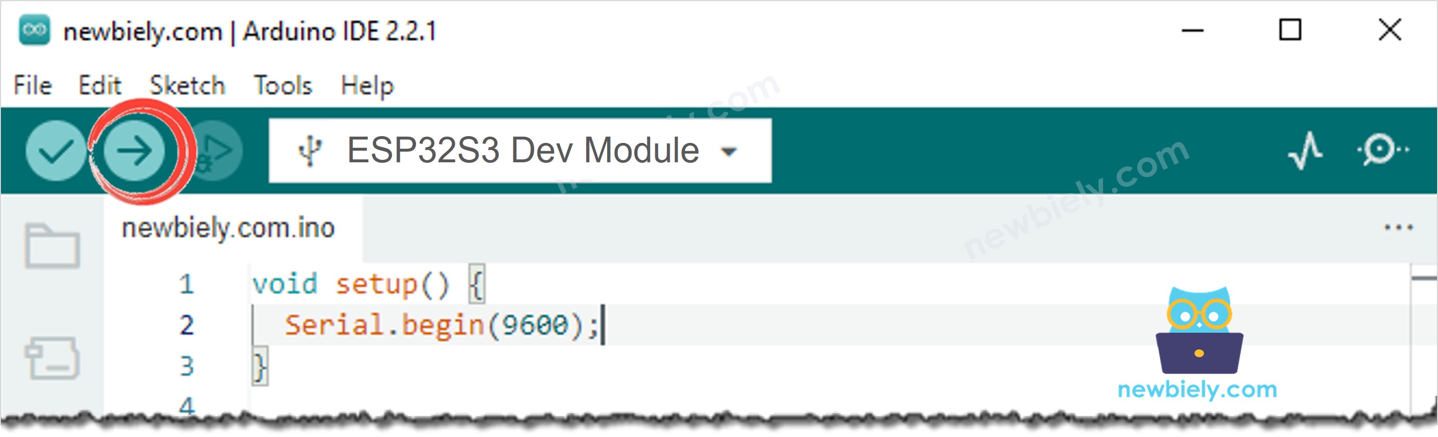
How to upload ESP32 S3 code on Arduino IDE
  1. Open Serial Monitor: Open Serial Monitor from the Tools menu in Arduino IDE.
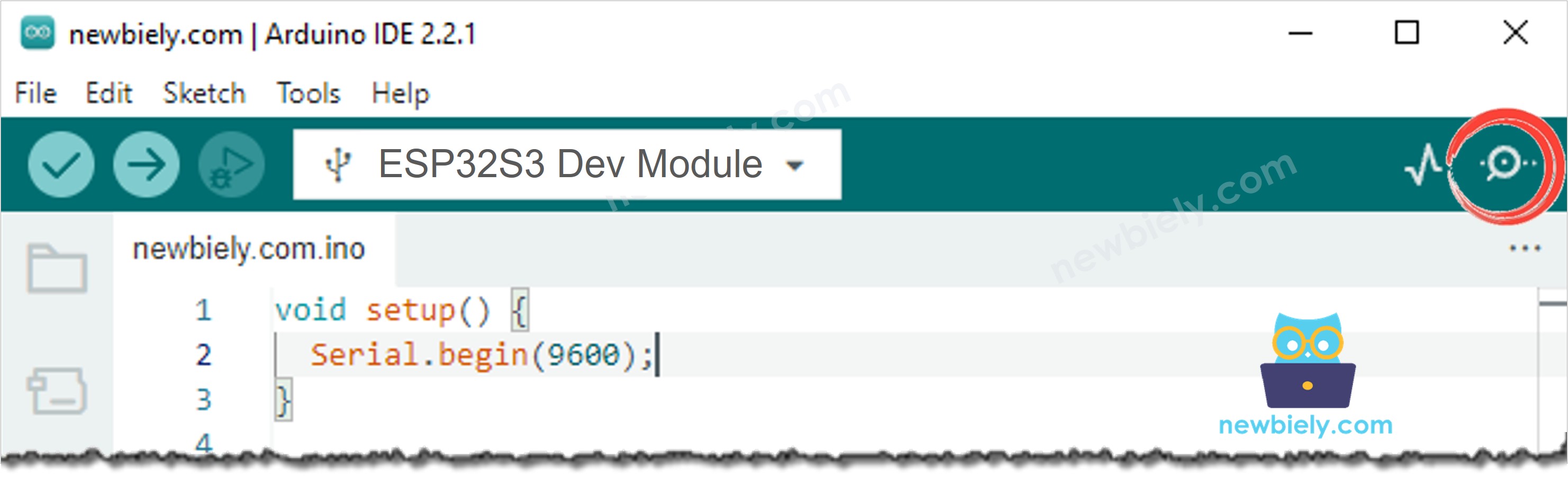
How to open serial monitor on Arduino IDE
  1. Press the button 4 times while the LED is blinking.
  2. Observe the LED: The LED toggles between ON and OFF every second.
  3. Check Serial Monitor output:
Newbiely | Arduino IDE 2.3.8
──
File
Edit
Sketch
Tools
Help
ESP32S3 Dev Module
Newbiely.ino
···
8 Serial.println("Hello World!");
Output
Serial Monitor
Message (Enter to send message to 'ESP32S3 Dev Module' on 'COM15')
New Line
9600 baud
[2026-06-16 10:00:01] Button state: 1 [2026-06-16 10:00:02] Button state: 0 [2026-06-16 10:00:05] Button state: 1 [2026-06-16 10:00:06] Button state: 0
Ln 11, Col 1
ESP32S3 Dev Module on COM15
2
  1. Pro Tip: Notice that you will NOT see all four button presses in the Serial Monitor. This is because the ESP32 S3 cannot detect input during the delay() blocking period — some presses are simply missed.

ESP32 S3 Code - Without Delay

The following code replaces delay() with millis() to track elapsed time without blocking the processor. Because the loop runs continuously, the ESP32 S3 can check the button state on every iteration even while it manages the LED blink timing independently.

/* * This ESP32 S3 code was developed by newbiely.com * * This ESP32 S3 code is made available for public use without any restriction * * For comprehensive instructions and wiring diagrams, please visit: * https://newbiely.com/tutorials/esp32-s3/esp32-s3-led-blink-without-delay */ #define LED_PIN 7 // The ESP32 S3 pin GPIO7 connected to LED #define BUTTON_PIN 5 // The ESP32 S3 pin GPIO5 connected to button #define BLINK_INTERVAL 1000 // interval at which to blink LED (milliseconds) // Variables will change: int ledState = LOW; // ledState used to set the LED int previousButtonState = LOW; // will store last time button was updated unsigned long previousMillis = 0; // will store last time LED was updated void setup() { Serial.begin(9600); // set the digital pin as output: pinMode(LED_PIN, OUTPUT); // set the digital pin as an input: pinMode(BUTTON_PIN, INPUT_PULLUP); } void loop() { // check to see if it's time to blink the LED; that is, if the difference // between the current time and last time you blinked the LED is bigger than // the interval at which you want to blink the LED. unsigned long currentMillis = millis(); if (currentMillis - previousMillis >= BLINK_INTERVAL) { // if the LED is off turn it on and vice-versa: ledState = (ledState == LOW) ? HIGH : LOW; // set the LED with the ledState of the variable: digitalWrite(LED_PIN, ledState); // save the last time you blinked the LED previousMillis = currentMillis; } // check button state's change int currentButtonState = digitalRead(BUTTON_PIN); if (currentButtonState != previousButtonState) { // print out the state of the button: Serial.println(currentButtonState); // save the last state of button previousButtonState = currentButtonState; } // DO OTHER WORKS HERE }

Detailed Instructions

  1. New to ESP32 S3? Complete our Getting Started with ESP32 S3 guide first.
  2. Upload the code: Copy the code above and upload it to your ESP32 S3.
  3. Press the button 4 times while the LED is blinking.
  4. Observe the LED: The LED still toggles between ON and OFF every second.
  5. Check Serial Monitor output:
Newbiely | Arduino IDE 2.3.8
──
File
Edit
Sketch
Tools
Help
ESP32S3 Dev Module
Newbiely.ino
···
8 Serial.println("Hello World!");
Output
Serial Monitor
Message (Enter to send message to 'ESP32S3 Dev Module' on 'COM15')
New Line
9600 baud
[2026-06-16 10:00:01] Button state: 1 [2026-06-16 10:00:02] Button state: 0 [2026-06-16 10:00:03] Button state: 1 [2026-06-16 10:00:04] Button state: 0 [2026-06-16 10:00:05] Button state: 1 [2026-06-16 10:00:06] Button state: 0 [2026-06-16 10:00:07] Button state: 1 [2026-06-16 10:00:08] Button state: 0
Ln 11, Col 1
ESP32S3 Dev Module on COM15
2
  1. Compare with delay version: All four button press events are now detected and logged correctly.
  2. Pro Tip: The millis() pattern is the foundation of multi-tasking on the ESP32 S3 — master it once and apply it to any timed operation throughout your projects.

Line-by-line Code Explanation

The above ESP32 S3 code contains line-by-line explanation. Please read the comments in the code!

Adding More Tasks

The following code demonstrates the full power of non-blocking programming on the ESP32 S3 by blinking two LEDs at different intervals while simultaneously monitoring a button — all without a single delay() call. Each task maintains its own timestamp variable, and the main loop cycles through all of them on every iteration so no task ever waits on another.
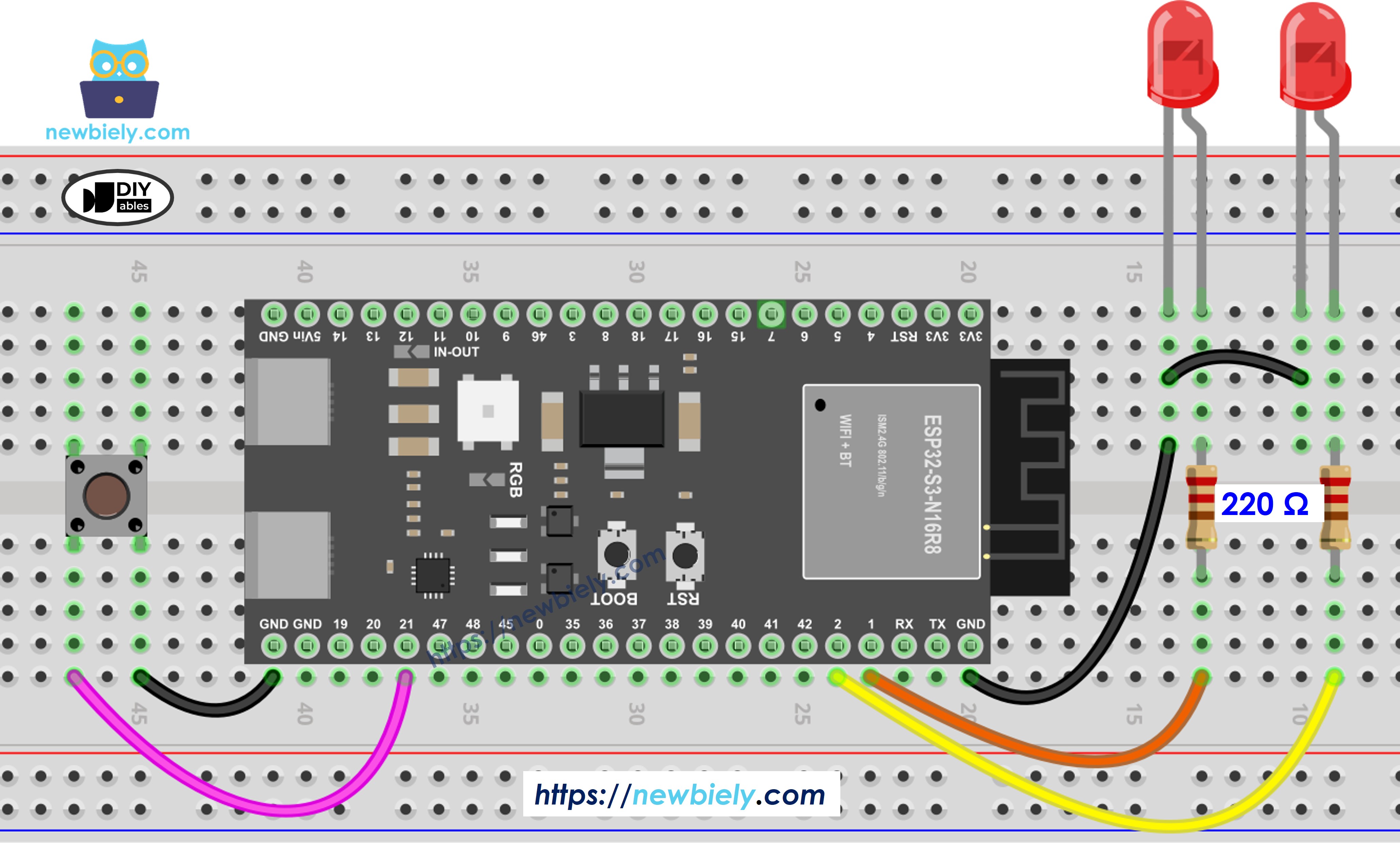
The wiring diagram between ESP32 S3 LED two button

This image is created using Fritzing. Click to enlarge image

/* * This ESP32 S3 code was developed by newbiely.com * * This ESP32 S3 code is made available for public use without any restriction * * For comprehensive instructions and wiring diagrams, please visit: * https://newbiely.com/tutorials/esp32-s3/esp32-s3-led-blink-without-delay */ #define LED_PIN_1 7 // The ESP32 S3 pin GPIO7 connected to LED 1 #define LED_PIN_2 6 // The ESP32 S3 pin GPIO6 connected to LED 2 #define BUTTON_PIN 5 // The ESP32 S3 pin GPIO5 connected to button #define BLINK_INTERVAL_1 1000 // interval at which to blink LED 1 (milliseconds) #define BLINK_INTERVAL_2 500 // interval at which to blink LED 2 (milliseconds) // Variables will change: int ledState_1 = LOW; // ledState used to set the LED 1 int ledState_2 = LOW; // ledState used to set the LED 2 int previousButtonState = LOW; // will store last time button was updated unsigned long previousMillis_1 = 0; // will store last time LED 1 was updated unsigned long previousMillis_2 = 0; // will store last time LED 2 was updated void setup() { Serial.begin(9600); // set the digital pin as output: pinMode(LED_PIN_1, OUTPUT); pinMode(LED_PIN_2, OUTPUT); // set the digital pin as an input: pinMode(BUTTON_PIN, INPUT_PULLUP); } void loop() { unsigned long currentMillis = millis(); // check to see if it's time to blink the LED 1 if (currentMillis - previousMillis_1 >= BLINK_INTERVAL_1) { // if the LED is off turn it on and vice-versa: ledState_1 = (ledState_1 == LOW) ? HIGH : LOW; // set the LED with the ledState of the variable: digitalWrite(LED_PIN_1, ledState_1); // save the last time you blinked the LED previousMillis_1 = currentMillis; } // check to see if it's time to blink the LED 2 if (currentMillis - previousMillis_2 >= BLINK_INTERVAL_2) { // if the LED is off turn it on and vice-versa: ledState_2 = (ledState_2 == LOW) ? HIGH : LOW; // set the LED with the ledState of the variable: digitalWrite(LED_PIN_2, ledState_2); // save the last time you blinked the LED previousMillis_2 = currentMillis; } // check button state's change int currentButtonState = digitalRead(BUTTON_PIN); if (currentButtonState != previousButtonState) { // print out the state of the button: Serial.println(currentButtonState); // save the last state of button previousButtonState = currentButtonState; } // DO OTHER WORKS HERE }

Application Ideas

Non-blocking timing with millis() is one of the most versatile patterns in ESP32 S3 programming, applicable far beyond simple LED blinking.

  1. Multi-sensor polling: Read temperature, humidity, and motion sensors at different intervals without any blocking between readings.
  2. Heartbeat indicator: Blink a status LED at a fixed rate while the ESP32 S3 simultaneously handles WiFi connections or MQTT messaging.
  3. Debounced button input: Combine millis() timing with button debouncing to reliably detect presses without interrupting other tasks.
  4. Timed relay control: Switch relays on and off at precise intervals for irrigation systems, lighting schedules, or industrial automation.
  5. Motor speed control: Manage PWM timing for motors or servos while monitoring safety sensors concurrently on the ESP32 S3.
  6. Data logging scheduler: Sample sensor data at regular intervals and buffer it for periodic upload over WiFi without blocking the sensor loop.

Video Tutorial

Watch the step-by-step video walkthrough for this ESP32 S3 project below.

Challenge Yourself

Once you have the non-blocking blink working on your ESP32 S3, push your understanding further with these progressively challenging exercises.

  1. Beginner: Change the blink interval from 1000 ms to 250 ms and observe how the LED blinks faster without affecting button detection.
  2. Beginner: Add a second LED and make it blink at twice the speed of the first LED using separate millis() timers.
  3. Intermediate: Use the button to toggle the LED blink on and off, so one press starts blinking and the next press stops it.
  4. Intermediate: Implement three independent millis() tasks: blink LED1 at 500 ms, blink LED2 at 300 ms, and read a button state at 50 ms intervals.
  5. Advanced: Replace the millis() timing logic with the ezLED library and compare code complexity and behavior on the ESP32 S3.

※ OUR MESSAGES

  • As freelancers, We are AVAILABLE for HIRE. See how to outsource your project to us
  • Please feel free to share the link of this tutorial. However, Please do not use our content on any other websites. We invested a lot of effort and time to create the content, please respect our work!