
ESP32 S3 - RFID
Learn how to connect an RC522 RFID/NFC reader module to an ESP32 S3 and read the unique identifier (UID) from any compatible RFID or NFC tag. This tutorial walks you through everything from wiring the hardware to uploading the finished sketch, so you can identify cards and tags with your ESP32 S3 in just a few minutes.
What you'll build:
- A circuit connecting the RFID-RC522 module to the ESP32 S3 over SPI
- Firmware that detects when an RFID or NFC tag is present and reads its UID
- A Serial Monitor output that prints the tag type and UID in hexadecimal format
- A foundation you can extend into access-control systems, inventory trackers, and smart-lock projects
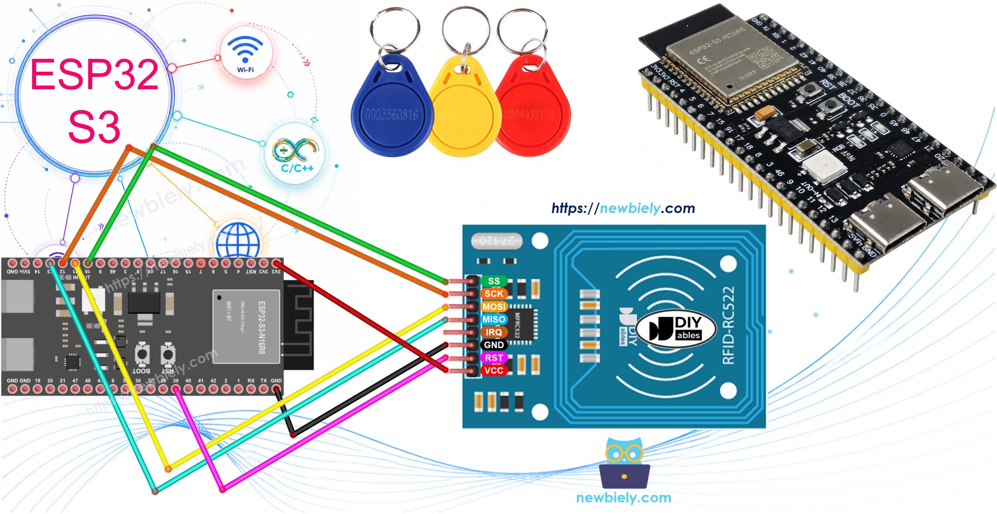
Hardware Preparation
Or you can buy the following kits:
| 1 | × | DIYables ESP32 S3 Starter Kit (ESP32 S3 included) | |
| 1 | × | DIYables Sensor Kit (18 sensors/displays) |
Additionally, some of these links are for products from our own brand, DIYables .
Overview of RFID-RC522 Module
The RFID-RC522 is a low-cost, 13.56 MHz RFID reader module based on the MFRC522 chip from NXP Semiconductors. It communicates with the ESP32 S3 over SPI and can detect and read ISO 14443A-compatible cards and tags — including the popular MIFARE card family — at distances of up to about 5 cm. The module operates at 3.3 V logic levels, making it directly compatible with the ESP32 S3 without any level-shifting circuitry.
Key Specifications
- Operating frequency: 13.56 MHz
- Communication interface: SPI (default), I2C, UART
- Operating voltage: 3.3 V (do not connect VCC to 5 V)
- Read range: up to ~5 cm (depending on tag and antenna orientation)
- Supported tag types: MIFARE 1KB, MIFARE Ultralight, MIFARE Classic, and other ISO 14443A cards
- Dimensions: approximately 40 mm × 60 mm
Pinout
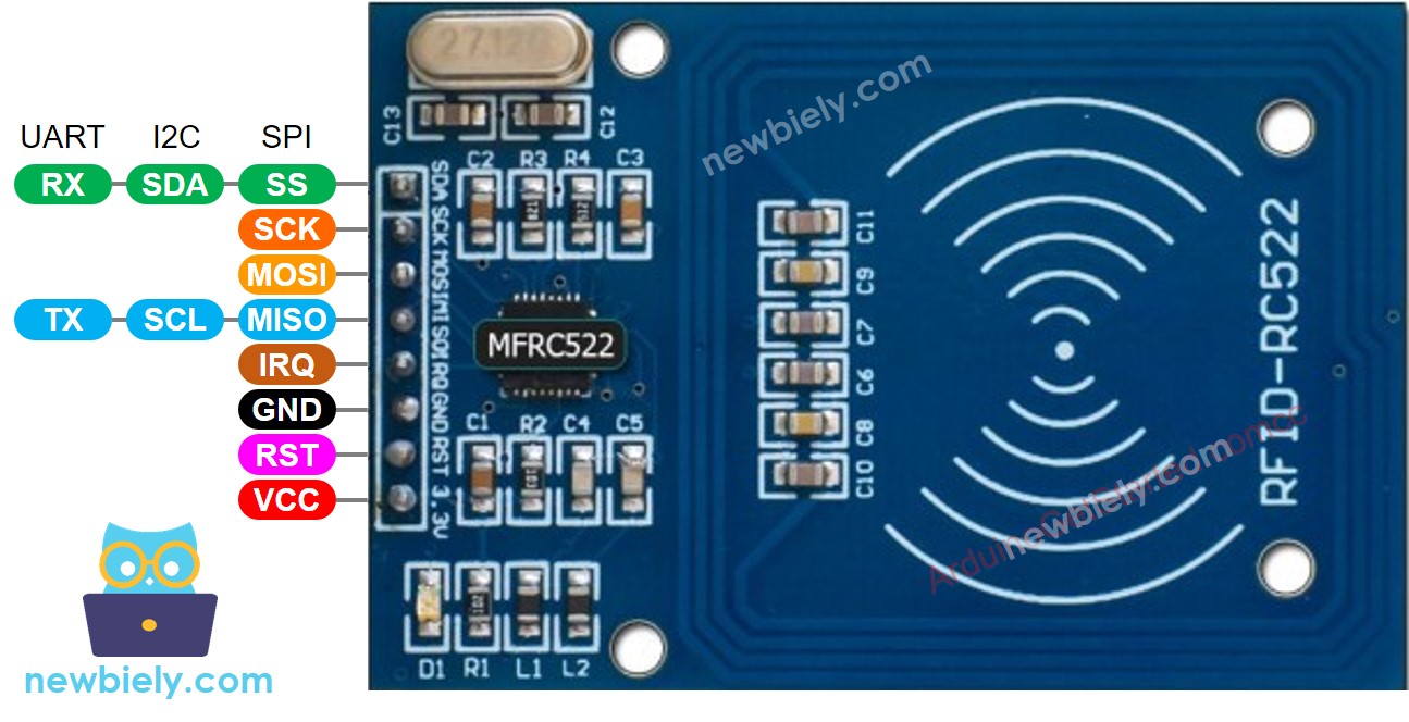
The RFID-RC522 module has 8 pins, some of which are shared among three communication interfaces: SPI, I2C, and UART. Only one communication mode can be active at a time. The pins are:
- GND: Connect to GND (0 V)
- VCC: Connect to 3.3 V — never connect to 5 V
- RST: Reset and power-down control — when pulled low, hard power-down is enabled; the module resets on the rising edge
- IRQ: Interrupt output — alerts the ESP32 S3 when an RFID tag enters the detection range (not used in this tutorial)
- MISO / SCL / TX: Serves as MISO (SPI), SCL (I2C), or TX (UART) depending on the active interface
- MOSI: MOSI data line when SPI is enabled
- SCK: Serial clock when SPI is enabled
- SS / SDA / RX: Serves as SS (SPI), SDA (I2C), or RX (UART) depending on the active interface
※ NOTE THAT:
- The pin order can vary between manufacturers. Always use the labels printed on the module itself. The image above shows the pinout of modules from the DIYables manufacturer.
- The RFID-RC522 module operates at 3.3 V. Connecting the VCC pin to 5 V will permanently damage the module.
- This tutorial uses the SPI interface for communication between the ESP32 S3 and the RFID-RC522 module.
Wiring Diagram
Connecting the RFID-RC522 module to the ESP32 S3 requires only a handful of jumper wires because the module uses the hardware SPI bus. Keep all wires short to reduce noise on the SPI lines and double-check each connection before powering the board.
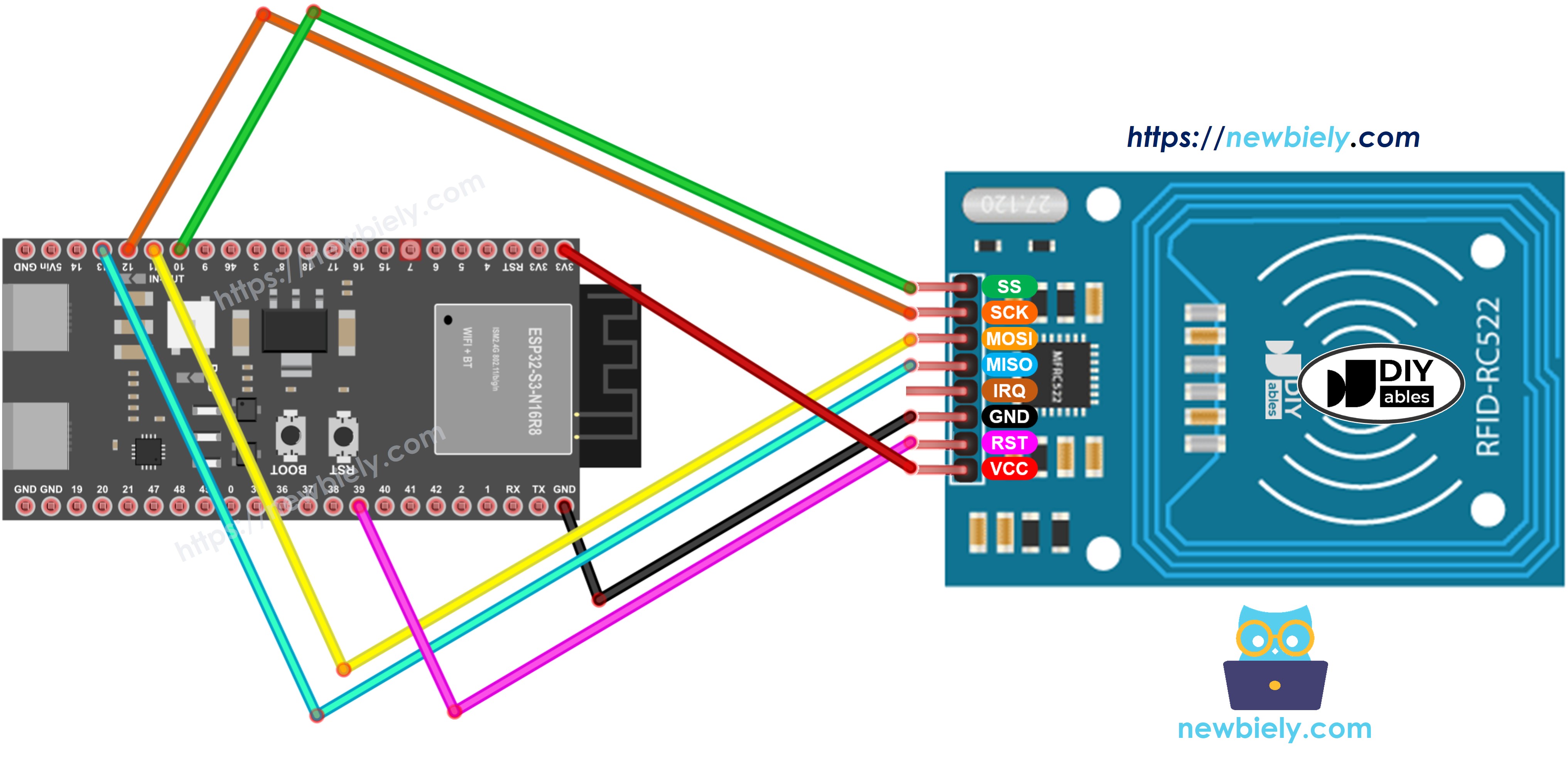
This image is created using Fritzing. Click to enlarge image
Safety Notes
The RFID-RC522 module runs on 3.3 V logic — connecting its VCC pin to the 5 V rail will immediately destroy the module, so always verify your power connection before applying power. The IRQ pin is left unconnected in this tutorial, which is fine; simply leave it floating if your wiring harness does not have a wire assigned to it. Because the ESP32 S3's SPI bus operates at 3.3 V, no level-shifting resistors are needed between the module and the board.
| RFID/NFC RC522 Module | ESP32 S3 Pin |
|---|---|
| SS pin | GPIO10 (SS/CS) |
| SCK pin | GPIO12 (SCK) |
| MOSI pin | GPIO11 (MOSI) |
| MISO pin | GPIO13 (MISO) |
| IRQ pin (not connected) | |
| GND pin | GND |
| RST pin | GPIO39 |
| VCC pin | 3.3V |
ESP32 S3 RFID/NFC Code
The following code initializes the SPI bus and the MFRC522 library, then continuously polls for a new tag. When a tag is detected, it reads the tag type and UID, prints both to the Serial Monitor in hexadecimal format, and then halts the card so the next tap will be treated as a fresh read.
Detailed Instructions
- New to ESP32 S3? Complete our Getting Started with ESP32 S3 guide first.
- Wire the circuit: Connect the RFID-RC522 module to the ESP32 S3 according to the wiring diagram above.
- Connect to computer: Plug the ESP32 S3 into your computer using a USB Type-C cable.
- Open Arduino IDE: Launch the Arduino IDE on your computer.
- Select your board: Choose ESP32 S3 from the board selector and select the correct COM port.
- Install the MFRC522 library: Click the Libraries icon on the left bar of the Arduino IDE.
- Search for the library: Type "MFRC522" in the search box, then look for the library by GithubCommunity.
- Install: Click the Install button to install the MFRC522 library.
- Search for MFRC522 created by GithubCommunity and click the Install button.
- Upload the code: Copy the code above, paste it into Arduino IDE, and click the Upload button.
- Open Serial Monitor: Open the Serial Monitor in Arduino IDE after uploading.
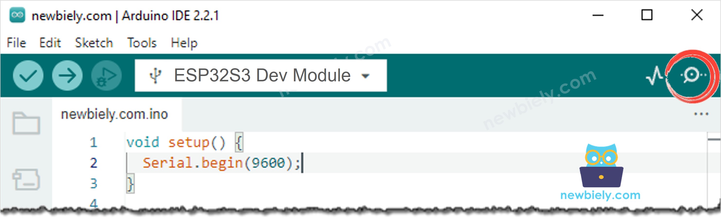
- Test the reader: Tap several RFID or NFC tags against the RC522 module.
- View the output: Watch the tag type and UID appear in the Serial Monitor.
- Pro Tip: Hold each tag flat and parallel to the RC522 antenna coil at a distance of 1–3 cm for the most reliable reads.
Serial Monitor Output
Open the Serial Monitor at 9600 baud after uploading the code, then tap RFID or NFC tags onto the RC522 module to see their type and UID printed for each scan.
Applications and Project Ideas
The ESP32 S3 paired with an RC522 RFID module opens up a wide range of identification and access-control applications that can be deployed with minimal extra hardware. Here are practical ways to put this circuit to work:
- Access control system: Grant or deny entry by comparing a scanned UID against a stored list of authorized cards.
- Attendance tracker: Log each RFID scan with a timestamp over Wi-Fi to a cloud spreadsheet or database for automated attendance records.
- Smart locker: Pair with a solenoid lock or servo to create a keyless locker that opens only for registered tags.
- Inventory management: Tag items with RFID stickers and scan them with the ESP32 S3 to automate stock counting.
- Library book tracker: Attach RFID tags to books and track check-outs and returns without manual barcode scanning.
- Pet or asset identification: Read passive RFID chips embedded in pets or equipment for automatic identification at a checkpoint.
- Game or puzzle controller: Use RFID tokens as physical inputs in escape rooms, treasure hunts, or interactive installations.
Video Tutorial
Watch the step-by-step video walkthrough for this ESP32 S3 project below.
Challenge Yourself
Now that your ESP32 S3 is successfully reading RFID and NFC tag UIDs, push the project further with these progressively harder challenges:
- Beginner: Store a known UID in the sketch and print "Access Granted" or "Access Denied" depending on whether the scanned tag matches.
- Beginner: Add an LED indicator that turns green on an authorized tag and red on an unauthorized tag.
- Intermediate: Connect a buzzer and play a short tone on every successful scan, with a different tone for unauthorized tags.
- Intermediate: Log every scanned UID with a timestamp to a Micro SD Card for a persistent audit trail.
- Advanced: Build a web-based admin panel using the ESP32 S3's Wi-Fi to add and remove authorized UIDs at runtime without re-flashing the firmware.
- Advanced: Combine the RC522 reader with a solenoid lock and a keypad so the door opens only when both the correct RFID card and a PIN are presented.