
ESP32 S3 - Potentiometer
This tutorial instructs you how to use the ESP32 S3 with a potentiometer. The potentiometer is one of the most versatile input devices, allowing you to translate physical rotation into a digital value your ESP32 S3 can read and act on.
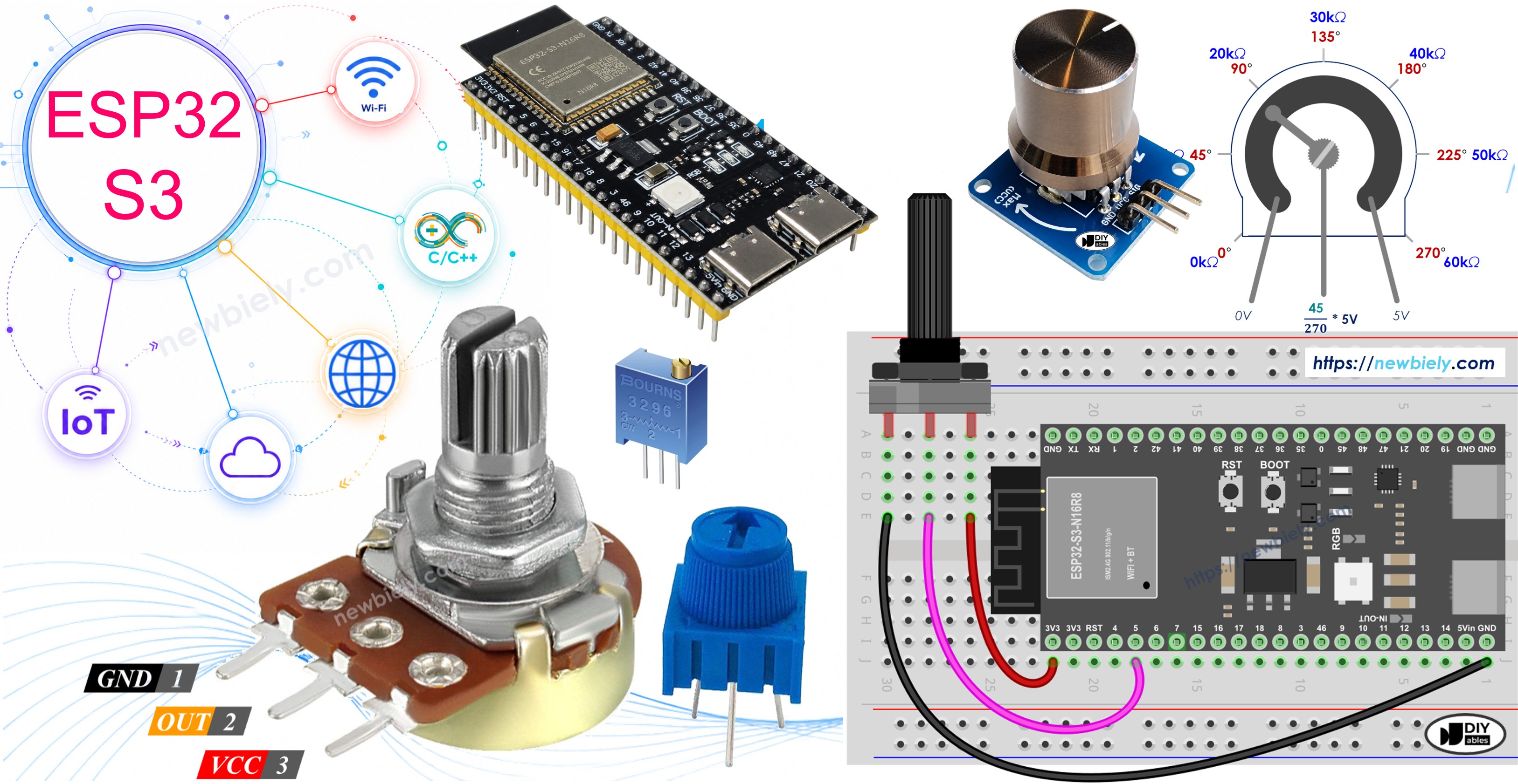
What you'll build:
- A circuit connecting a potentiometer to the ESP32 S3
- Code that reads the raw analog value from the potentiometer
- A voltage conversion that maps the ADC reading to real volts
- Serial Monitor output that displays live analog and voltage readings
Hardware Preparation
Or you can buy the following kits:
| 1 | × | DIYables ESP32 S3 Starter Kit (ESP32 S3 included) | |
| 1 | × | DIYables Sensor Kit (18 sensors/displays) |
Additionally, some of these links are for products from our own brand, DIYables .
Overview of Potentiometer
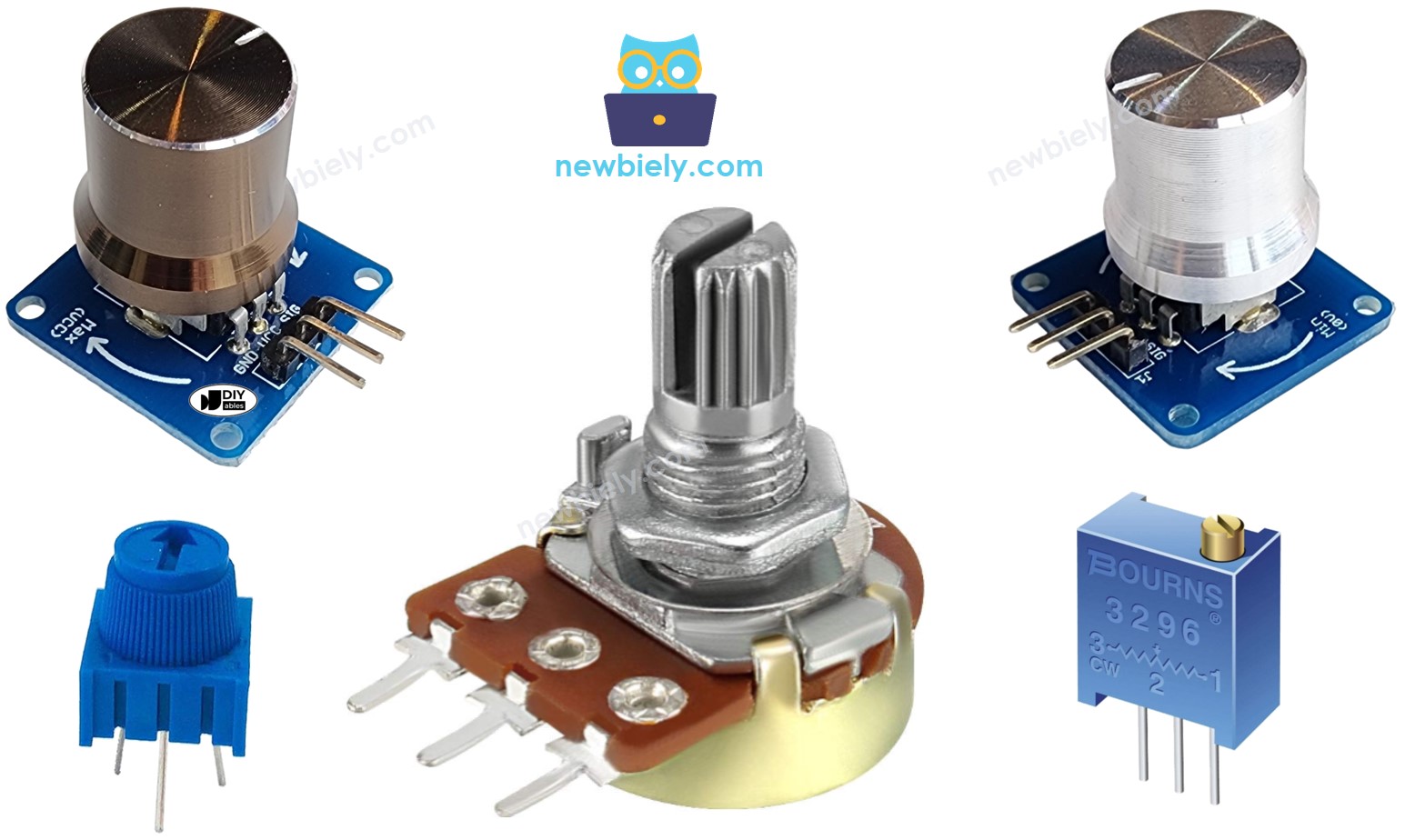
The potentiometer (also known as a rotary angle sensor) is a three-terminal variable resistor used to control settings such as speaker volume, room temperature, or lamp brightness. By rotating its shaft, you vary the resistance between the output pin and each supply rail, producing a proportional output voltage that your microcontroller can read.
Key Specifications
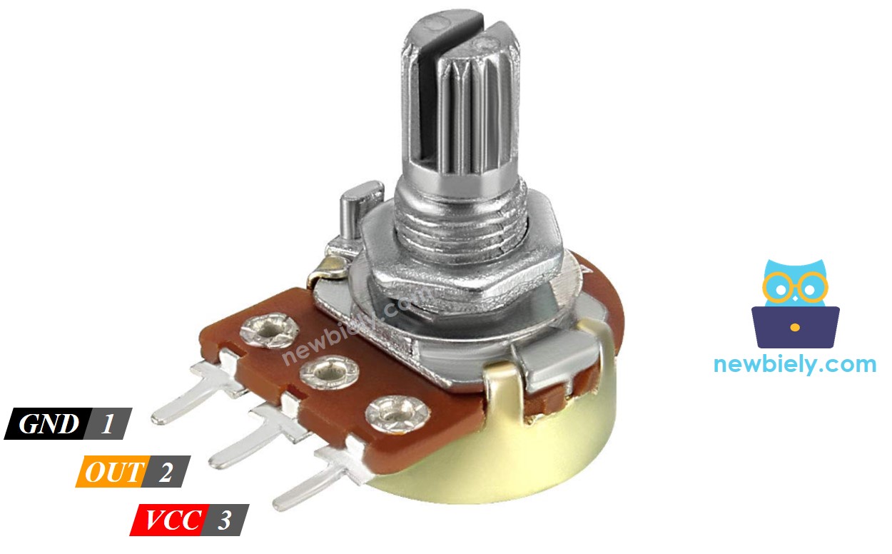
Potentiometer Pinout
A potentiometer usually has 3 pins:
- VCC pin: connect this pin to VCC (5V or 3.3V)
- GND pin: connect this pin to GND (0V)
- Output pin: outputs the voltage to the ESP32 S3's analog input pin
※ NOTE THAT:
The GND pin and VCC pin are interchangeable
How Potentiometer Works
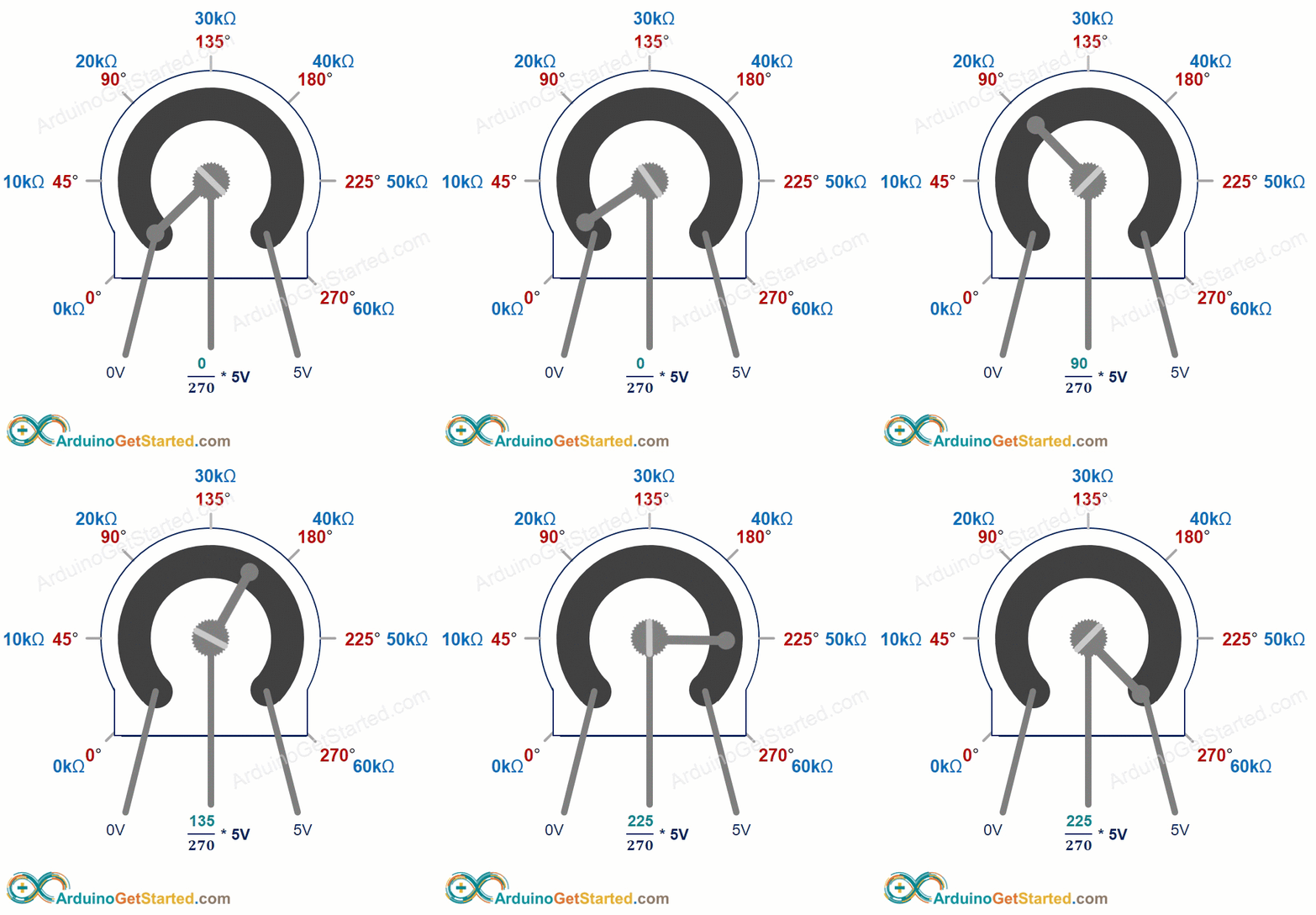
The potentiometer's shaft can be rotated from 0° (closest to GND pin) to an angle (closest to VCC pin), called ANGLE_MAX.
The voltage on the output pin is directly proportional to the shaft's angle, varying from 0 V to VCC. The table below shows the relationship between angle and output voltage:
| Angle | Voltage |
|---|---|
| 0° | 0v |
| ANGLE_MAX° | VCC |
| angle° | angle° × VCC / ANGLE_MAX° |
※ NOTE THAT:
The ANGLE_MAX value depends on the manufacturer.
ESP32 S3 - Rotary Potentiometer
The ESP32 S3's analog input pin converts a voltage (between 0 V and 3.3 V) into an integer value (between 0 and 4095), called an ADC value or analog value.
You can connect the potentiometer's output pin to an ESP32 S3 analog input pin and then read the analog value from that pin. The analog value can be rescaled into other useful values:
- Rescale the analog value to the potentiometer's angle.
- Rescale the analog value to the potentiometer's voltage.
- Rescale the analog value to a controllable setting (e.g. speaker volume, room temperature, or lamp brightness).
Rescale Range
| FROM | TO | |||
|---|---|---|---|---|
| Angle | rotated by user | 0° | → | ANGLE_MAX° |
| Voltage | from potentiometer's pin | 0V | → | 3.3V |
| ADC value | read by ESP32 S3 | 0 | → | 4095 |
| Setting value | converted by ESP32 S3 | VALUE_MIN | → | VALUE_MAX |
Wiring Diagram between Potentiometer and ESP32 S3
Connect the potentiometer to your ESP32 S3 using a breadboard and jumper wires as shown in the diagram below. Ensure the potentiometer's output pin connects to an ADC-capable GPIO on the ESP32 S3.
- How to connect ESP32 S3 and potentiometer using breadboard
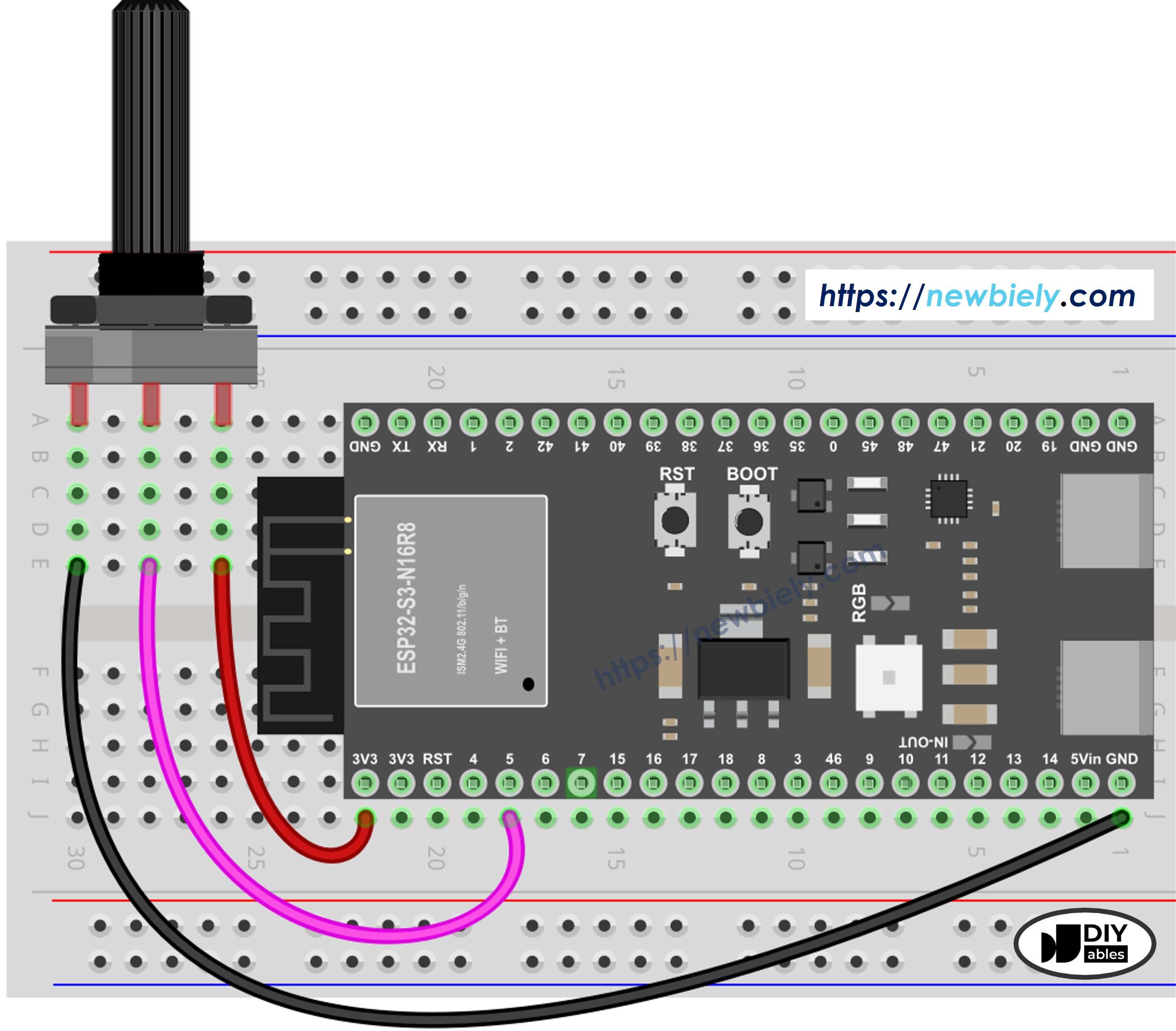
This image is created using Fritzing. Click to enlarge image
Safety Notes
Always power the potentiometer from the ESP32 S3's 3.3 V rail rather than 5 V, since the ESP32 S3's ADC input is rated for a maximum of 3.3 V. Double-check your wiring before powering up to avoid applying over-voltage to the analog pin.
| Potentiometer Pin | ESP32 S3 Pin |
|---|---|
| VCC | 3.3V |
| GND | GND |
| Output | GPIO5 (or any ADC-capable GPIO) |
How To Program Potentiometer
Reading a potentiometer with the ESP32 S3 requires only a few lines of Arduino code. The following code snippets show each step — from reading the raw ADC value to converting it into meaningful units.
- Read the value from an input pin connected to the output pin of the potentiometer using the analogRead() function.
- Rescale to the potentiometer's angle using the map() function.
- Rescale to the potentiometer's voltage:
- Rescale to a controllable value (e.g. volume, brightness, or motor speed):
- For example, rescaling to the brightness of an LED. As mentioned in the PWM tutorial, LED brightness can be controlled with a PWM value from 0 (always OFF) to 255 (always ON). You can map the analog value to LED brightness like this:
If you want to dim the LED from a nightlight level to the brightest:
※ NOTE THAT:
The map() function can only rescale the analog value to an int or long type value. If the controllable value is a float type, use the floatMap() function instead.
floatMap() function:
ESP32 S3 Code
The following code reads the raw ADC value and the corresponding voltage from the potentiometer, then prints both to the Serial Monitor every 500 ms. Upload the sketch to your ESP32 S3 and open the Serial Monitor to see live readings as you rotate the knob.
Detailed Instructions
- New to ESP32 S3? Complete our Getting Started with ESP32 S3 guide first.
- Copy the above code and paste it into the Arduino IDE.
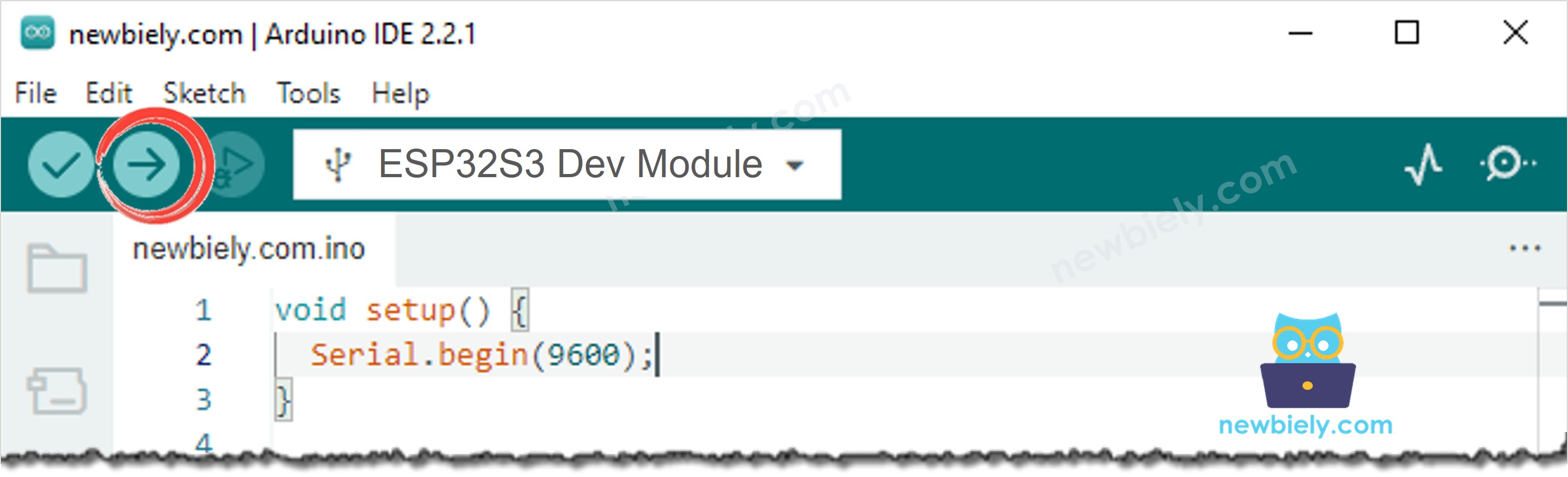
- Compile and upload the code to the ESP32 S3 board by clicking the Upload button in Arduino IDE.
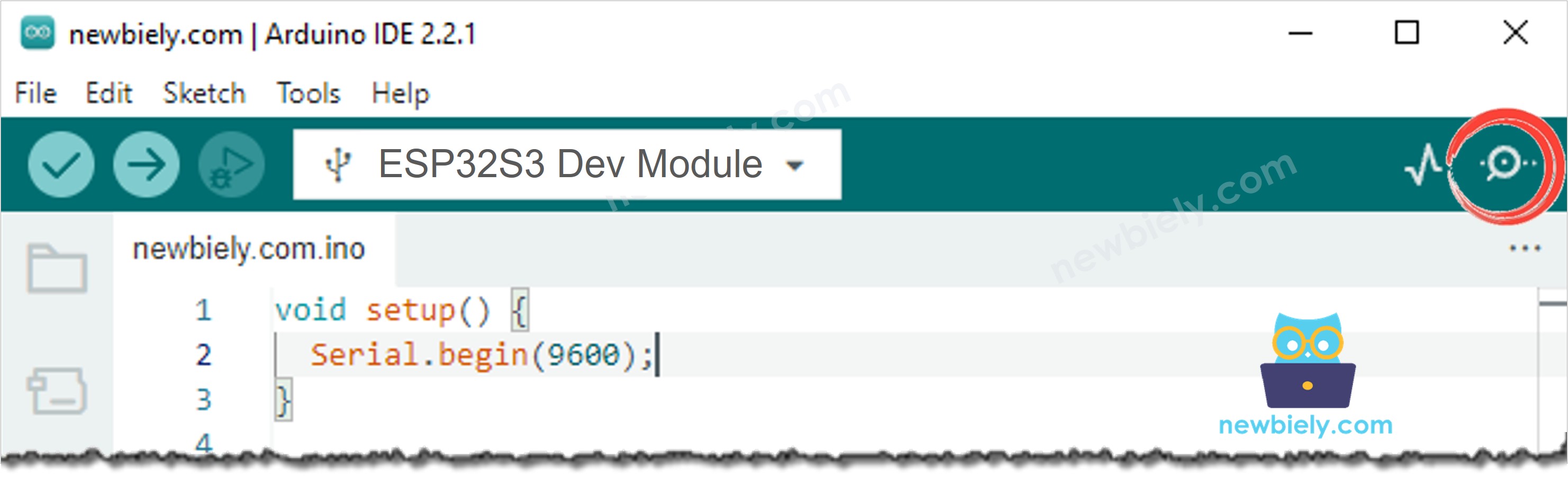
- Open the Serial Monitor in Arduino IDE.
- Rotate the potentiometer knob slowly from one end to the other.
- Observe the live readings in the Serial Monitor.
- Pro Tip: Try mapping the analog value to an LED brightness using PWM to see a physical effect of the potentiometer in real time.
Serial Monitor
After uploading, the Serial Monitor will display the raw analog value alongside the calculated voltage. Rotate the potentiometer to see the values change in real time. The following readings were captured in 2026:
※ NOTE THAT:
This tutorial uses the analogRead() function to read values from the ADC connected to the potentiometer. The ESP32 S3 ADC is suitable for projects that do NOT require high accuracy. For projects needing precise measurements, note:
- The ESP32 S3 ADC is not perfectly accurate and may need calibration. Each board can behave slightly differently.
- Calibration can be challenging for beginners and may not always yield exact results.
For high-precision projects, consider using an external ADC (e.g. ADS1115) with the ESP32 S3. If you still want to calibrate the ADC, refer to ESP32 ADC Calibration Driver.
Applications
Potentiometers are commonly used wherever a user needs to dial in a setting interactively. Some practical applications for your ESP32 S3 projects include:
- Volume control: Adjust audio output level in a Bluetooth or wired speaker system.
- Brightness dimmer: Control the intensity of LEDs or an LCD backlight.
- Motor speed control: Set the target RPM of a DC motor via PWM mapping.
- Temperature setpoint: Allow users to dial a desired room temperature for a thermostat.
- Servo position: Rotate a servo motor to a user-selected angle in a robotic arm.
Video Tutorial
Watch the step-by-step video walkthrough for this ESP32 S3 project below.
Challenges
Now that you have a working potentiometer circuit on the ESP32 S3, try extending the project with these exercises to deepen your understanding.
- Beginner: Change the GPIO pin used for the potentiometer and update the code accordingly, then verify the readings still work correctly.
- Intermediate: Use the potentiometer value to control the brightness of an LED connected to a PWM-capable pin on the ESP32 S3.
- Advanced: Build a simple UI on an OLED display that shows a progress bar representing the current potentiometer position as a percentage.