
ESP32 S3 - Buzzer
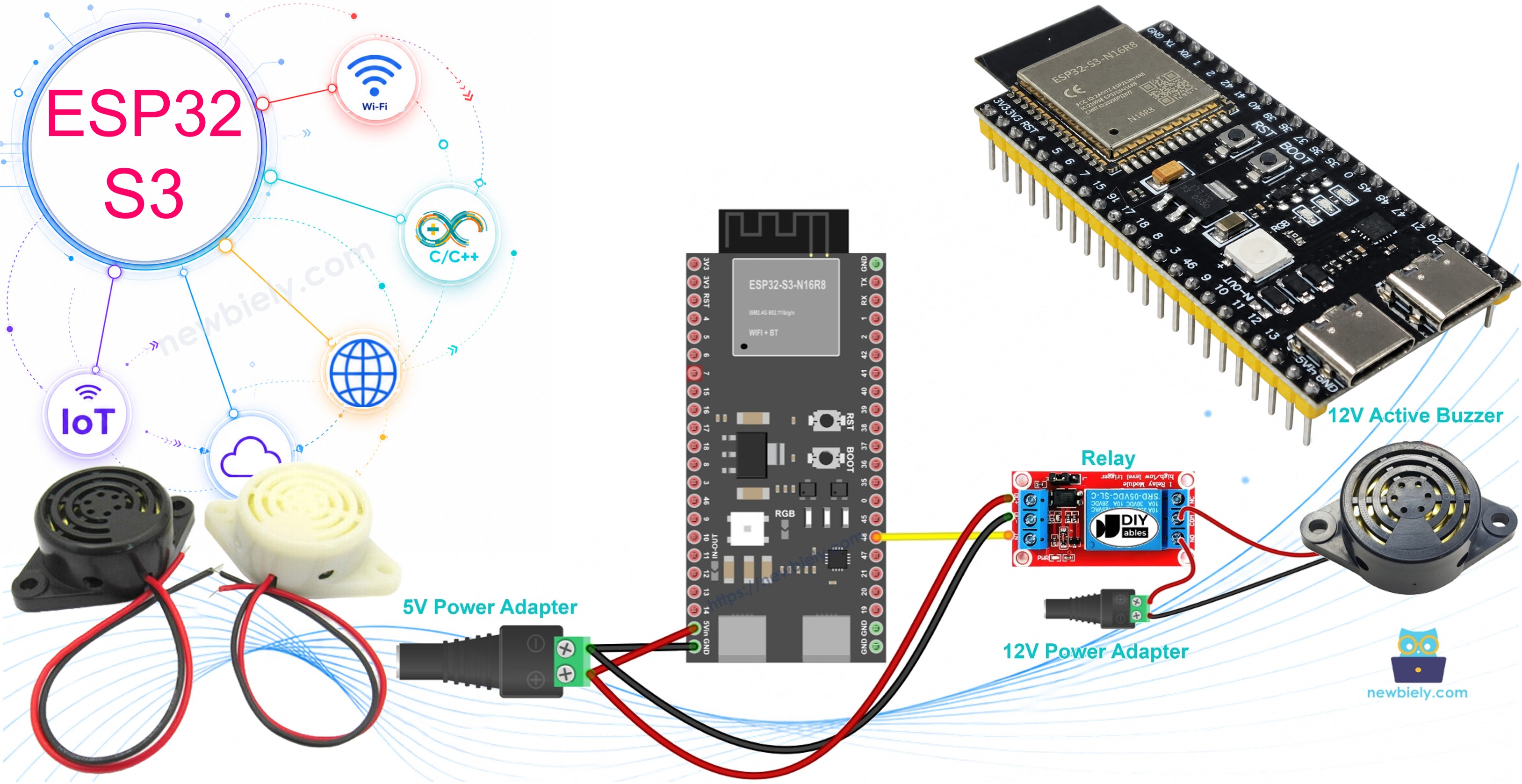
Learn how to program your ESP32 S3 to control a 12V active buzzer and generate loud, attention-grabbing sounds perfect for alarms and notifications. This beginner-friendly tutorial walks you through the wiring, code, and concepts needed to build a fully working buzzer project with the ESP32 S3.
What you'll build:
- A relay-controlled 12V active buzzer circuit connected to an ESP32 S3
- Firmware that cycles the buzzer ON for 1 second and OFF for 2 seconds in a repeating alarm pattern
- A safe, isolated switching design that protects your ESP32 S3 from high-voltage components
- A foundation you can extend into real-world security alarms, notification systems, and IoT alert devices
Note: If you want to control a 5V active/passive buzzer, check out this ESP32 S3 Piezo Buzzer tutorial
Hardware Preparation
Or you can buy the following kits:
| 1 | × | DIYables ESP32 S3 Starter Kit (ESP32 S3 included) | |
| 1 | × | DIYables Sensor Kit (18 sensors/displays) |
Additionally, some of these links are for products from our own brand, DIYables .
Overview of 12V Active Buzzer
The 12V Active Buzzer is an electronic component that produces a loud, high-decibel sound well suited to alarm systems and attention alerts. Unlike passive buzzers that require a PWM signal, an active buzzer contains a built-in oscillator, so it emits sound the moment power is applied — no tone generation needed in your code.
Key Specifications
The buzzer operates on a 12V DC supply and delivers significantly more volume than a standard 5V piezo buzzer, making it ideal for outdoor environments or noisy spaces. Because the ESP32 S3 outputs only 3.3V, the buzzer must be powered by an external 12V supply and switched through a relay module. This design also keeps your ESP32 S3 electrically isolated from the higher-voltage circuit, protecting the microcontroller from damage.
Pinout
The 12V Active Buzzer has just two connection points, making wiring straightforward.
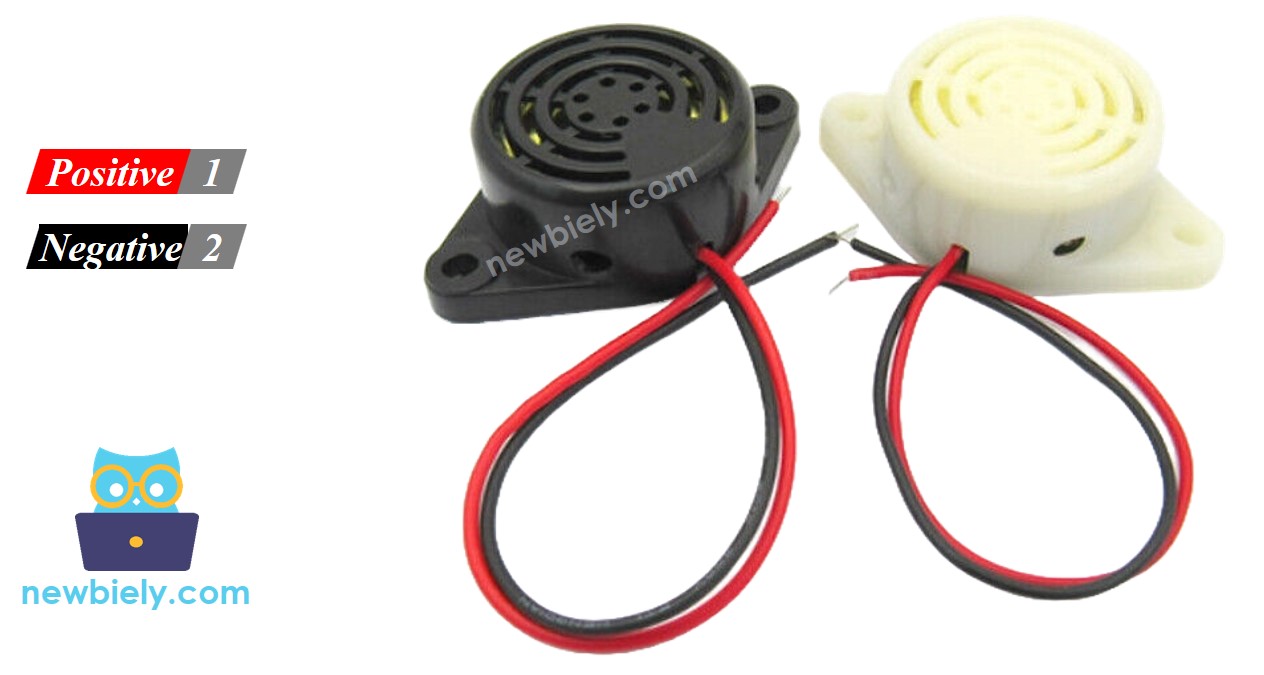
- Negative (-) pin (black): Connect to GND of the 12V DC power supply
- Positive (+) pin (red): Connect to the 12V positive rail of the DC power supply (switched through the relay)
How to Control 12V Active Buzzer
The ESP32 S3 outputs only 3.3V logic, which is far below the 12V the buzzer requires and unsafe to connect directly. The solution is to place a relay module between the ESP32 S3 and the buzzer circuit. The ESP32 S3 drives the relay coil with a single digital GPIO pin; the relay then acts as a mechanical switch, connecting or disconnecting the 12V supply to the buzzer on demand.
Important: If you're new to relays, check out the ESP32 S3 - Relay tutorial to understand pinout, operation, and programming basics before proceeding.
Wiring Diagram
Connect your ESP32 S3 to the 12V active buzzer through a relay module using the diagram and table below. Keep the 12V power wiring on one side of the breadboard and the ESP32 S3 signal wires on the other to reduce the risk of interference.
Safety Notes
Always verify the polarity of your 12V power supply before applying power — reversed polarity can permanently damage the buzzer. Route 12V wiring away from ESP32 S3 signal lines to avoid electrical noise that could cause erratic behavior.
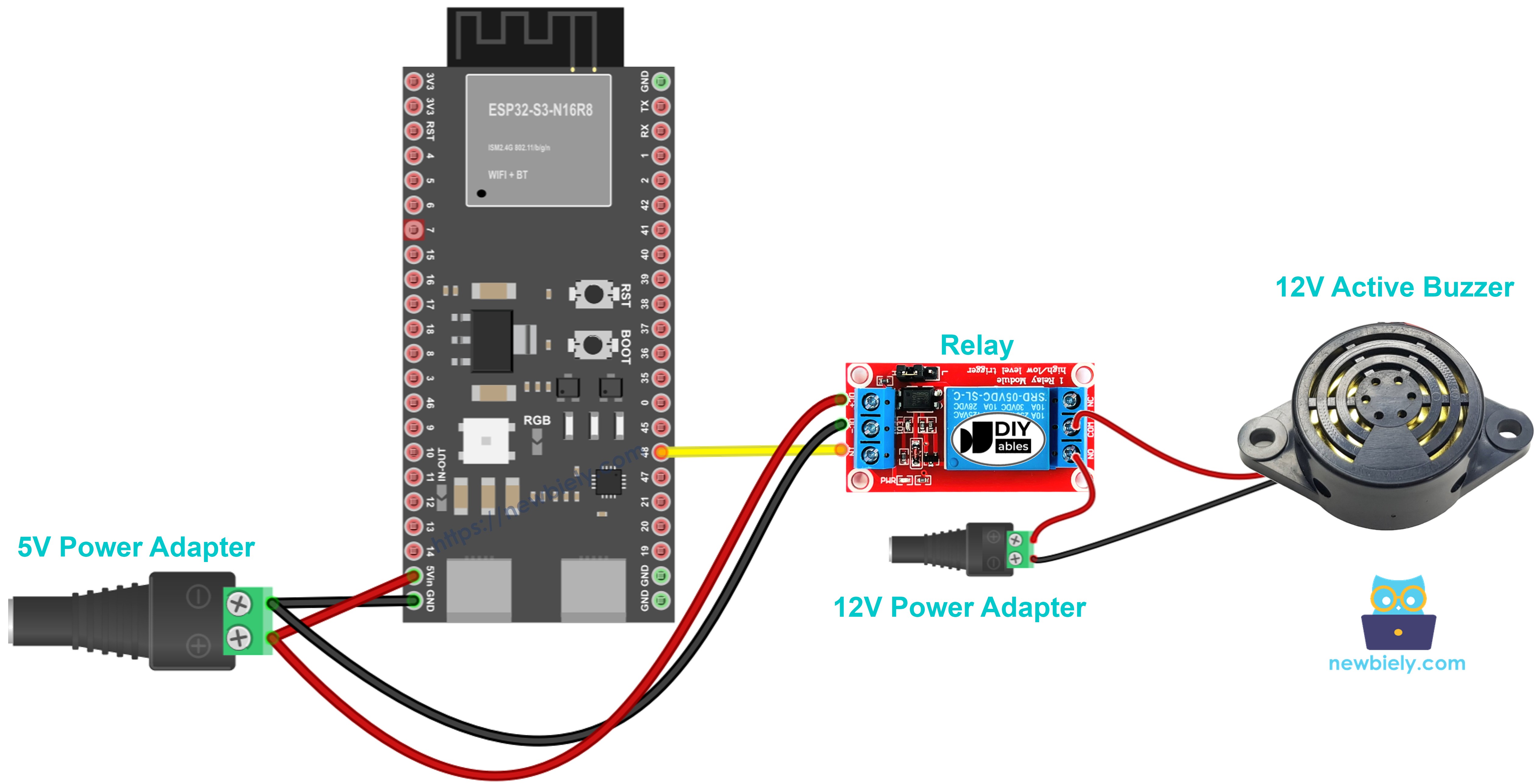
This image is created using Fritzing. Click to enlarge image
| Component Pin | Connection Point |
|---|---|
| ESP32 Pin 2 | Relay Signal Pin (IN) |
| ESP32 GND | Relay GND |
| ESP32 5V | Relay VCC |
| Relay COM | 12V Power Supply (+) |
| Relay NO | Buzzer (+) Red Wire |
| Buzzer (-) Black Wire | 12V Power Supply GND (-) |
ESP32 S3 Code
The following sketch controls the 12V active buzzer through the relay by toggling GPIO pin 2 at a fixed interval. It turns the buzzer ON for 1 second and then OFF for 2 seconds, repeating indefinitely to produce a recognizable alarm-style beep pattern. The logic is intentionally simple so you can easily modify the timing to suit your application.
Detailed Instructions
- New to ESP32 S3? Complete our Getting Started with ESP32 S3 guide first.
- Connect hardware: Wire the ESP32 S3, relay, buzzer, and 12V power supply according to the wiring diagram above.
- Connect to PC: Plug your ESP32 S3 into your computer using the USB Type-C cable.
- Open Arduino IDE: Launch the Arduino IDE and select the correct board and port for your ESP32 S3.
- Upload code: Copy the code above, paste it into the Arduino IDE, and click the Upload button.
- Test buzzer: Listen for the buzzer to beep ON for 1 second and OFF for 2 seconds repeatedly.
- Verify operation: The relay's onboard LED should blink in sync with the buzzer sound, confirming the relay is switching correctly.
- Pro Tip: Adjust the delay() values in the code to create different beep patterns — shorter delays produce rapid alarm sounds, while longer delays create slow, deliberate warning beeps.
Code Explanation
The code comments explain each line in detail. Read through them to understand exactly how the buzzer control works and where to make changes for your own projects.
The sketch uses four core Arduino functions: pinMode() configures GPIO 2 as a digital output, digitalWrite(HIGH) energizes the relay coil to connect 12V power to the buzzer, digitalWrite(LOW) releases the relay to cut power and silence the buzzer, and delay() pauses execution to control how long each state lasts.
Applications and Project Ideas
The ESP32 S3 paired with a 12V active buzzer opens the door to a wide range of practical, real-world projects that demand attention-grabbing audio alerts.
- Security alarm system: Trigger loud alerts when motion sensors detect intrusion.
- Timer notifications: Create kitchen timers or workout interval buzzers that are impossible to ignore.
- Door/window alerts: Sound an alarm when doors or windows open unexpectedly.
- Water leak detector: Combine with a moisture sensor to provide immediate leak warnings.
- Temperature warnings: Pair with a temperature sensor to raise an overheat alarm.
- Reminder system: Build a medication or appointment reminder device with a loud, unmissable alert.
- IoT alarm system: Use the ESP32 S3's built-in WiFi to create a remotely controlled or monitored security alert.
Video Tutorial
Watch the step-by-step video walkthrough for this ESP32 S3 project below.
Challenge Yourself
Once your basic ESP32 S3 buzzer project is working, push your skills further with these progressively harder challenges.
- Beginner: Modify the code to produce an SOS pattern (3 short beeps, 3 long beeps, 3 short beeps).
- Beginner: Add a push button so the buzzer only sounds while the button is held down.
- Intermediate: Program multiple different beep durations and pauses to create a recognizable melody.
- Intermediate: Integrate a PIR motion sensor so the alarm triggers automatically on movement detection.
- Advanced: Build a smartphone-controlled alarm using the ESP32 S3's WiFi and the Blynk IoT platform.
- Advanced: Design a multi-zone alarm system where each zone has its own buzzer controlled independently by the ESP32 S3.