
ESP32 S3 - LED RGB
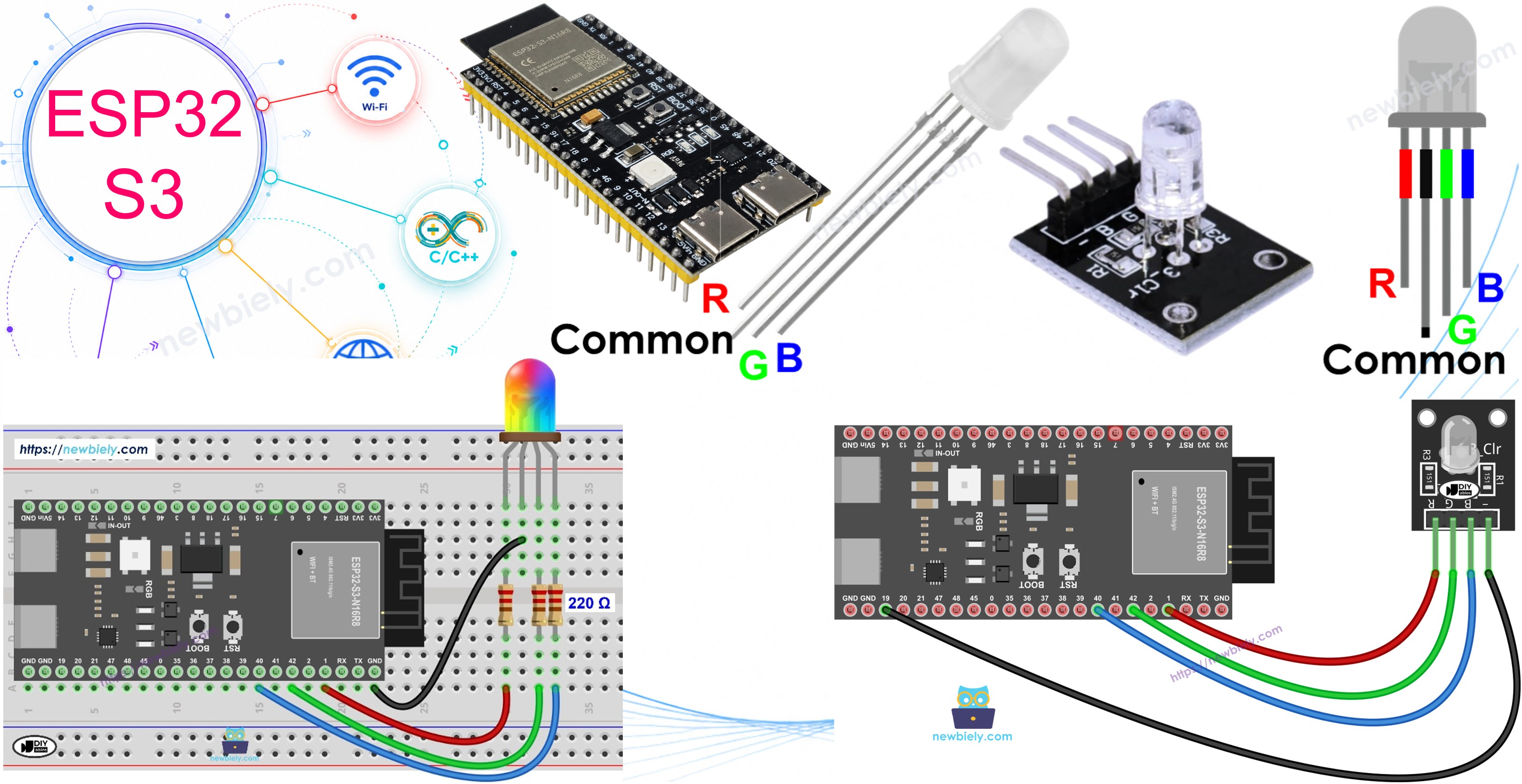
The ESP32 S3 can drive an RGB LED to produce any color by mixing red, green, and blue light through PWM signals — giving you over 16 million possible color combinations from a single component. This tutorial walks you through wiring, coding, and understanding the color-mixing principles so you can add vivid visual feedback to your ESP32 S3 projects.
What you'll build:
- A circuit connecting an RGB LED (or RGB LED module) to the ESP32 S3
- An Arduino sketch that cycles through three distinct colors using PWM
- A reusable setColor() helper function for clean, readable color control
- A foundation for any project that needs full-color visual output on the ESP32 S3
Hardware Preparation
Or you can buy the following kits:
| 1 | × | DIYables ESP32 S3 Starter Kit (ESP32 S3 included) | |
| 1 | × | DIYables Sensor Kit (18 sensors/displays) |
Additionally, some of these links are for products from our own brand, DIYables .
Overview of RGB LED
An RGB LED combines three individual LEDs — red, green, and blue — inside a single package, allowing any color to be produced by adjusting the brightness of each element independently. Because the three light sources are so close together, the human eye perceives their blended output as a single, unified color.
Key Specifications
A common-cathode RGB LED has four pins: one shared ground and one control pin per color channel. Each channel behaves like a standard LED, operating at roughly 2–3 V forward voltage with a current draw near 20 mA, so a current-limiting resistor is required for each channel unless you use a pre-built RGB LED module that already includes resistors. The ESP32 S3 drives each channel with a PWM value between 0 (off) and 255 (maximum brightness), giving 256 intensity levels per channel and over 16 million combined color possibilities.
RGB LED Pinout
The RGB LED includes four pins that map to each light element:
- R (red) pin: Controls the red color element
- G (green) pin: Controls the green color element
- B (blue) pin: Controls the blue color element
- Common (Cathode−) pin: Connect this pin to GND (0V)
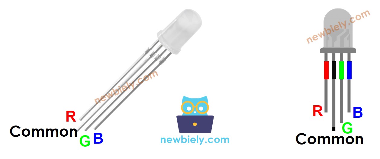
To hook up an RGB LED to the ESP32 S3, you must add current-limiting resistors to each color pin. This can complicate the wiring — luckily, an RGB LED module comes with pre-built current-limiting resistors and is the recommended option for beginners.
RGB LED Module also includes four pins:
- Common (Cathode−) pin: Needs to be connected to GND (0V)
- R (red): Pin used to control red
- G (green): Pin used to control green
- B (blue): Pin used to control blue
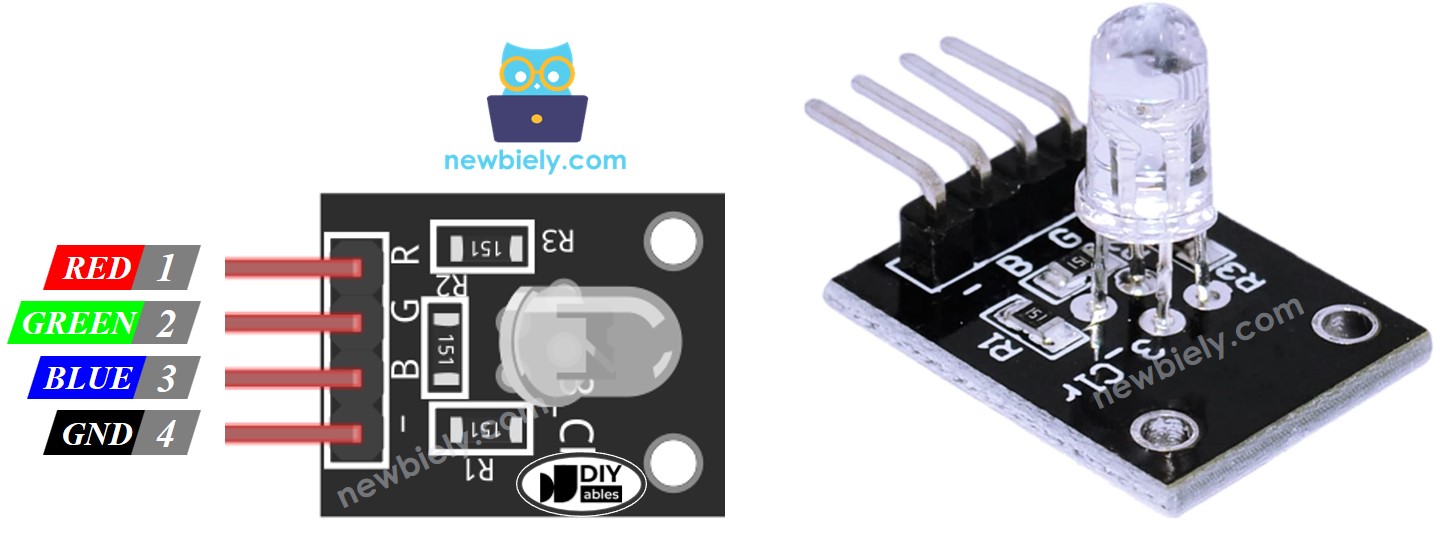
※ NOTE THAT:
According to the common pin, there are two types of LED: common anode and common cathode. This tutorial uses a common cathode LED.
How RGB LED Works
In terms of physics, every color is a combination of three primary elements: Red (R), Green (G), and Blue (B). Each element's value ranges from 0 to 255, and their combination creates 256 × 256 × 256 = over 16 million total colors.
When the ESP32 S3 generates PWM signals on the R, G, and B pins, the RGB LED displays the color corresponding to those duty cycle values. By changing the duty cycle of each PWM signal (from 0 to 255), the RGB LED can display any color. The color values of Red (R), Green (G), and Blue (B) correspond to the PWM duty cycle on the R, G, and B pins respectively.
Wiring Diagram between RGB LED and ESP32 S3
Connect the RGB LED module to the ESP32 S3 by running three wires from the color pins to digital output pins, then connect the common cathode pin directly to any GND pin on the board. If you are using a bare RGB LED (without the module), remember to add a 220 ohm current-limiting resistor in series with each color pin.
Safety Notes
Always use current-limiting resistors (220 ohm per channel) when wiring a bare RGB LED — omitting them risks permanently damaging the LED or burning out the ESP32 S3 GPIO pins. Using an RGB LED module eliminates this concern because the resistors are already built in.
- Wiring diagram between ESP32 S3 and RGB LED
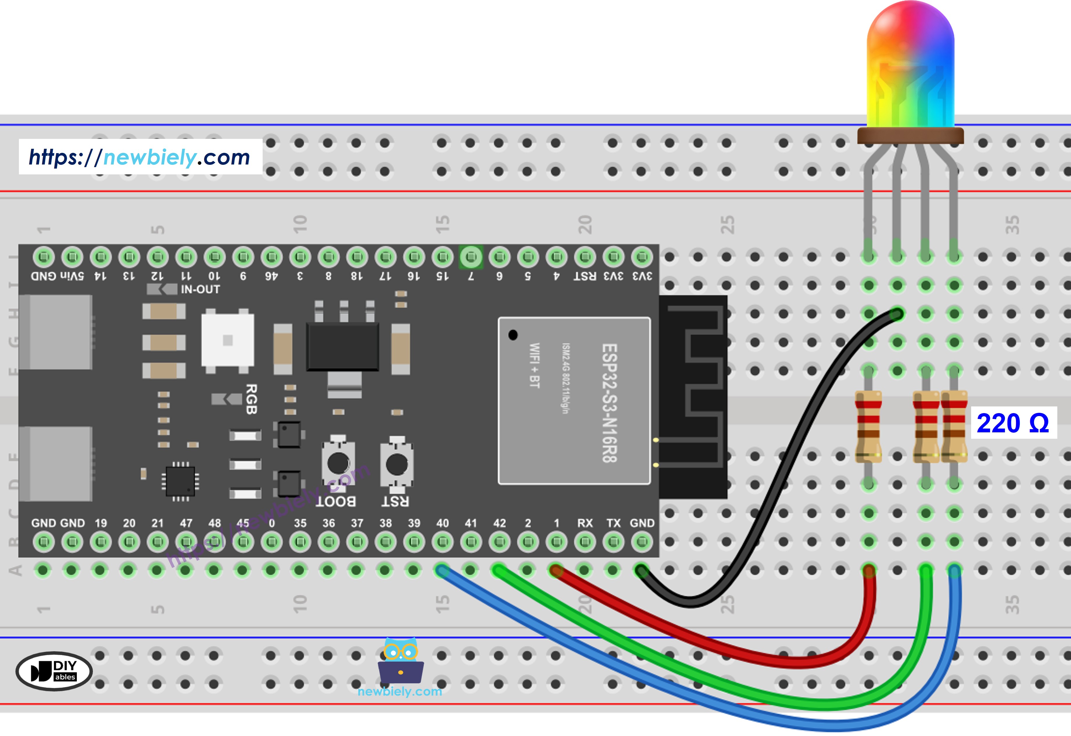
This image is created using Fritzing. Click to enlarge image
- Wiring diagram between ESP32 S3 and RGB LED module
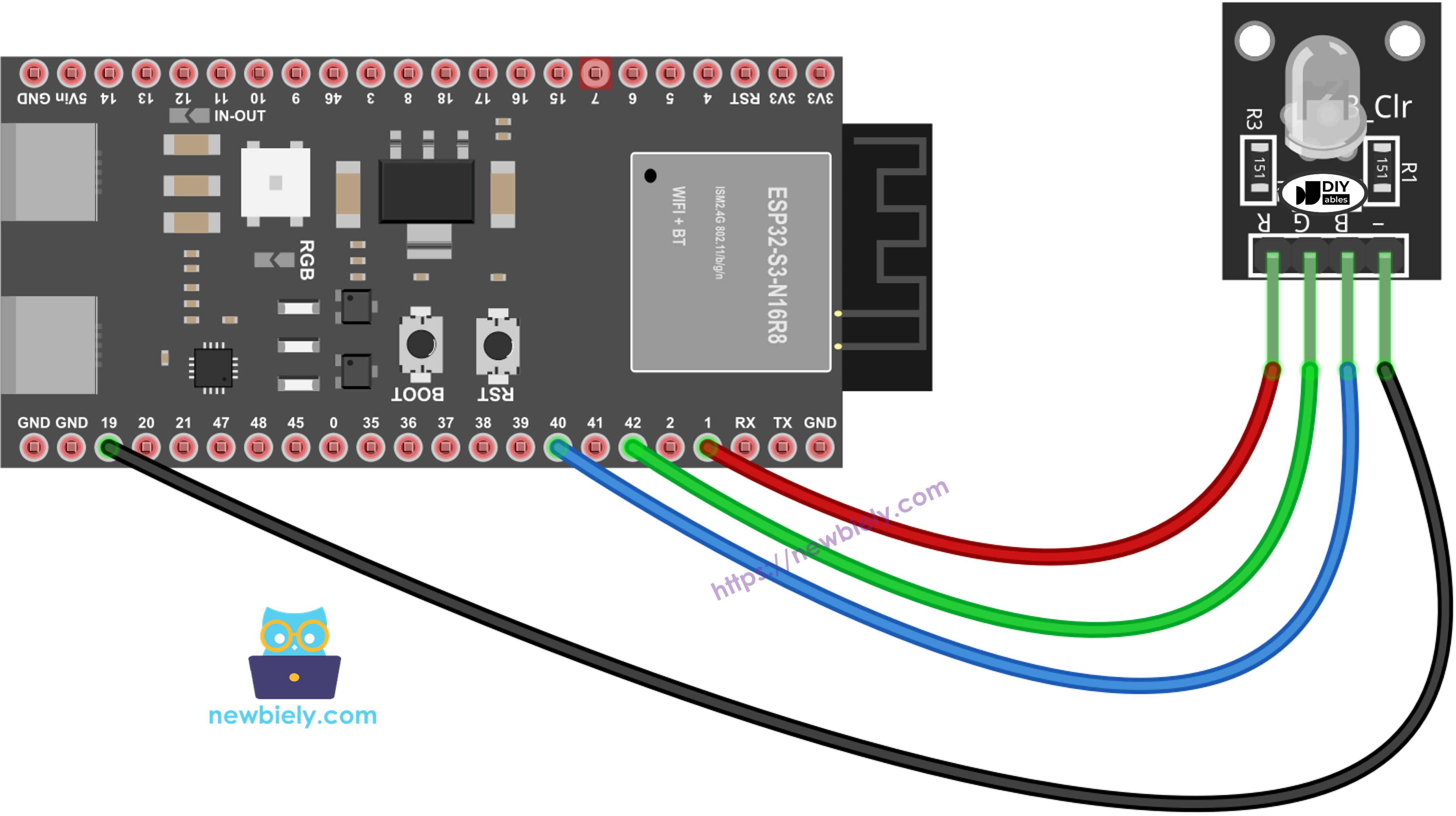
This image is created using Fritzing. Click to enlarge image
| RGB LED Pin | Component | ESP32 S3 Pin |
|---|---|---|
| R (red) | 220Ω Resistor (or built-in on module) | GPIO1 |
| G (green) | 220Ω Resistor (or built-in on module) | GPIO42 |
| B (blue) | 220Ω Resistor (or built-in on module) | GPIO40 |
| Common (Cathode−) | Direct Wire | GND |
How To Control RGB LED
Controlling the RGB LED with the ESP32 S3 involves three steps: selecting a target color, converting it to R/G/B values, and writing those values with analogWrite(). The following steps walk through the process using the color #00979D as an example.
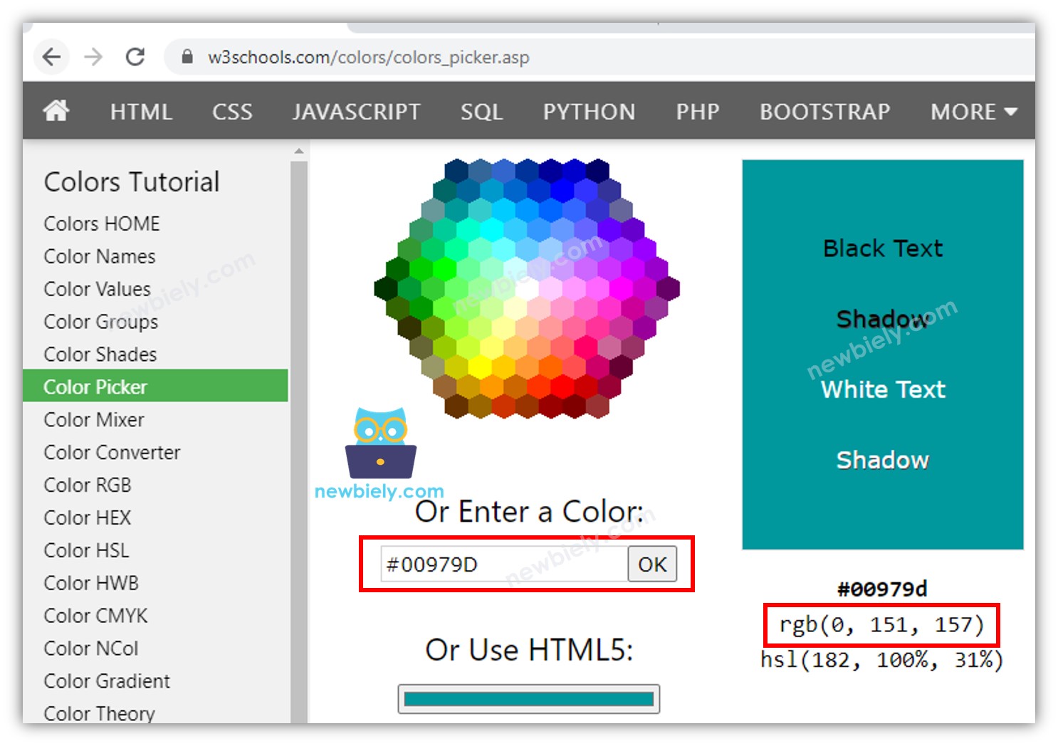
- Find the color code. Tips:
- You can pick up the color code you want from the color picker
- If you want to use a color from an image, use the online Colors From Image tool
- Convert the color code to R, G, B values using the tool from w3schools. In this case: R = 0, G = 151, B = 157
- Define the ESP32 S3 pins connected to R, G, and B. For example:
- Configure these ESP32 S3 pins as outputs:
- Control the LED to emit the target color (#00979D → R = 0, G = 151, B = 157):
ESP32 S3 Code
Detailed Instructions
The following code cycles the RGB LED through three colors in sequence. Before uploading, make sure your wiring matches the diagram above and your Arduino IDE is configured for the ESP32 S3 board.
- New to ESP32 S3? Complete our Getting Started with ESP32 S3 guide first.
- Wire the Circuit: Connect the RGB LED (or module) to the ESP32 S3 according to the wiring diagram above.
- Connect Board: Plug the ESP32 S3 into your computer using a USB Type-C cable.
- Open Arduino IDE: Launch the Arduino IDE on your computer.
- Select Board: Choose ESP32 S3 and its corresponding COM port.
- Copy Code: Copy the code below and paste it into Arduino IDE.
The following code changes the LED color among three values in sequence:
- #00C9CC (R = 0, G = 201, B = 204)
- #F7788A (R = 247, G = 120, B = 138)
- #34A853 (R = 52, G = 168, B = 83)
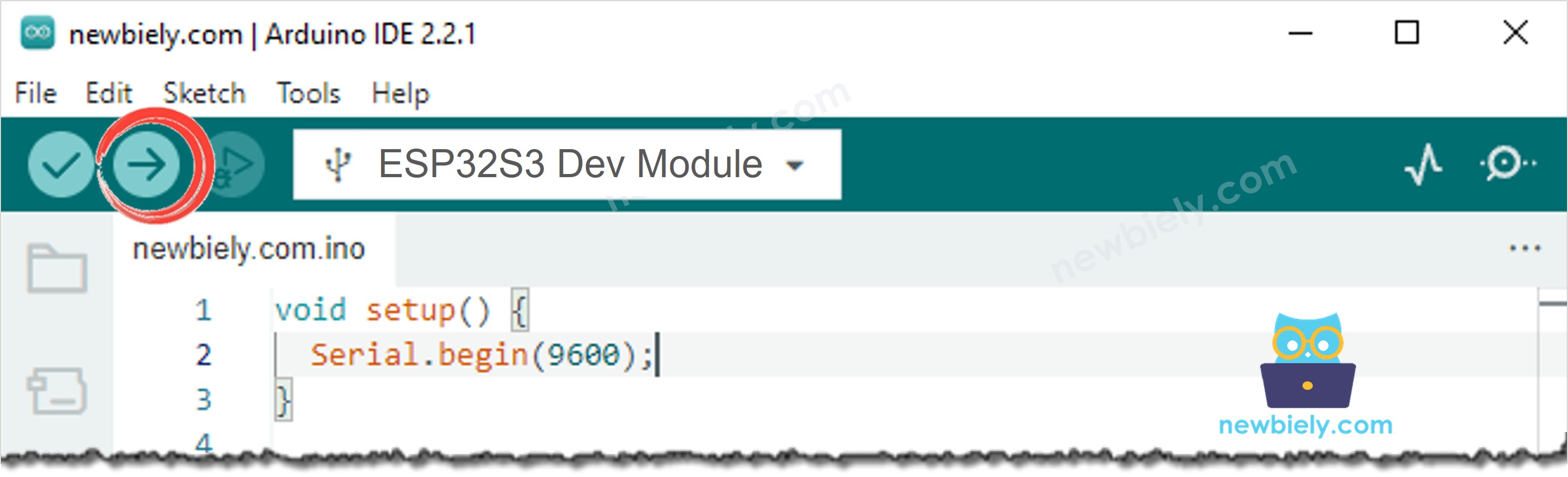
- Upload Code: Click the Upload button in Arduino IDE to compile and upload.
- Observe Results: Watch the RGB LED cycle through three different colors, each held for one second.
- Pro Tip: Use an online color picker to find the hex code for any color you want, convert it to R/G/B values, and plug those numbers directly into analogWrite() calls to display that exact color on your LED.
Line-by-line Code Explanation
The above ESP32 S3 code contains line-by-line explanation. Please read the comments in the code!
When using many colors, we could shorten the code by creating a function:
When your project needs to display many different colors, repeating three analogWrite() calls for each color quickly becomes unwieldy. The following code refactors the color logic into a reusable setColor() function, making the sketch cleaner and easier to maintain.
Serial Monitor Output
The RGB LED tutorial does not produce Serial Monitor output by default, but you can add Serial.begin(9600) in setup() and log each color change to verify your code is running as expected. Sample output after adding serial logging would look like:
Application and Project Ideas
RGB LED color control is a powerful building block for a wide range of ESP32 S3 projects that need expressive visual output.
- Mood Lamp: Build a WiFi-controlled ambient light that lets users select any color from a web page, leveraging the ESP32 S3's built-in wireless capabilities.
- Status Indicator: Display green for normal, yellow for warning, and red for error states in an IoT monitoring system connected to the ESP32 S3.
- Notification Light: Flash a specific color when the ESP32 S3 receives a particular MQTT message, email alert, or webhook trigger.
- Temperature Visualizer: Map sensor temperature readings to a color gradient — blue for cold, green for comfortable, red for hot — using the ESP32 S3's analog inputs.
- Game Controller Feedback: Use color changes to signal game states, hit detection, or player turns in an ESP32 S3-powered interactive project.
- Night Light Timer: Cycle through warm colors in the evening and gradually shift to cooler tones at night on a time-based schedule driven by the ESP32 S3's internal clock.
Video Tutorial
Watch the step-by-step video walkthrough for this ESP32 S3 project below.
Challenge Yourself
Once your RGB LED is cycling colors reliably on the ESP32 S3, these progressively challenging exercises will help you deepen your understanding of PWM, color theory, and timing.
- Beginner: Change the three colors in the loop to colors of your own choosing using an online color picker to find the R/G/B values.
- Beginner: Add a fourth color and adjust the delays so each color displays for a different amount of time.
- Intermediate: Create a smooth rainbow fade effect that cycles continuously through the full color spectrum using a loop and setColor().
- Intermediate: Add a push button that advances the ESP32 S3 to the next color in the sequence each time it is pressed.
- Advanced: Implement a smooth color crossfade between any two colors by interpolating the R, G, and B values step by step without using delay().
- Advanced: Connect a photoresistor to the ESP32 S3 and use ambient light readings to automatically adjust the LED color or brightness in real time.