
ESP32 S3 Camera - Save Photo to SD Card When Motion Detected
This tutorial instructs you how to build a small security camera with the ESP32 S3. A PIR motion sensor watches the room. When somebody walks in front of it, the ESP32 S3 takes a photo and saves it to a microSD card. The board works alone. It does not need WiFi, and it does not need a computer.
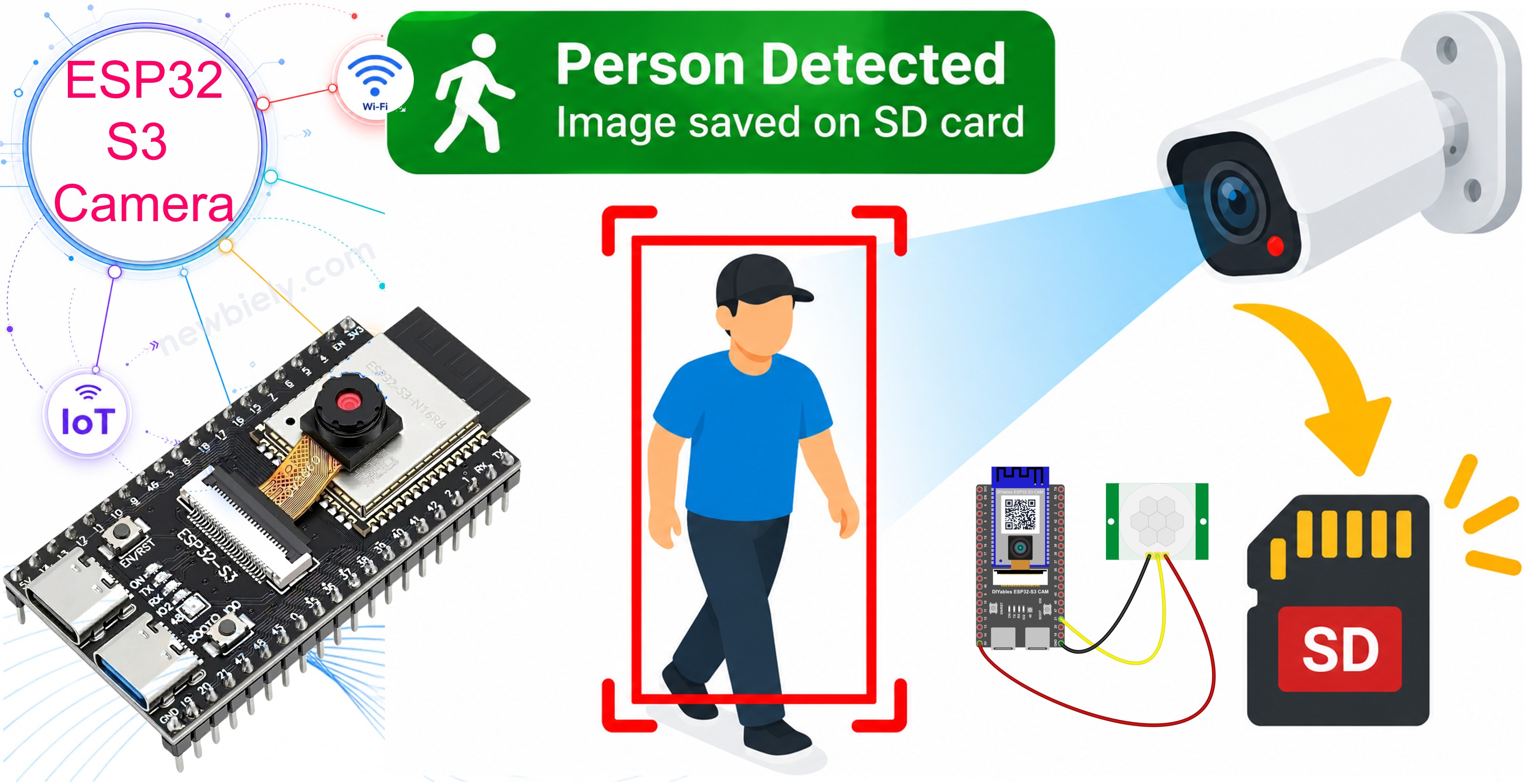
What you'll build:
- An ESP32 S3 camera with a PIR motion sensor
- A photo saved to the microSD card every time the sensor sees a movement
- A quiet time, so one person walking does not fill your card with 50 photos
- A camera that works without internet
Hardware Preparation
Or you can buy the following kits:
| 1 | × | DIYables Sensor Kit (18 sensors/displays) |
Additionally, some of these links are for products from our own brand, DIYables .
※ NOTE THAT:
The ESP32 S3 camera board has 40 pins, but the screw terminal block and the breakout board have 44 pins. They still work together. Put the camera board in the center of the 44-pin board, so 2 pins stay free on the left side and 2 pins stay free on the right side.
The screw terminal block lets you connect wires with a screwdriver, with no soldering. The breakout board gives you easy pin headers for a breadboard.
Overview of PIR Motion Sensor
A PIR motion sensor sees the heat of a human body. PIR means "Passive InfraRed". The sensor does not send anything out. It only listens to the infrared light (heat) around it. When a warm body moves in front of it, the heat pattern changes, and the sensor tells the ESP32 S3.
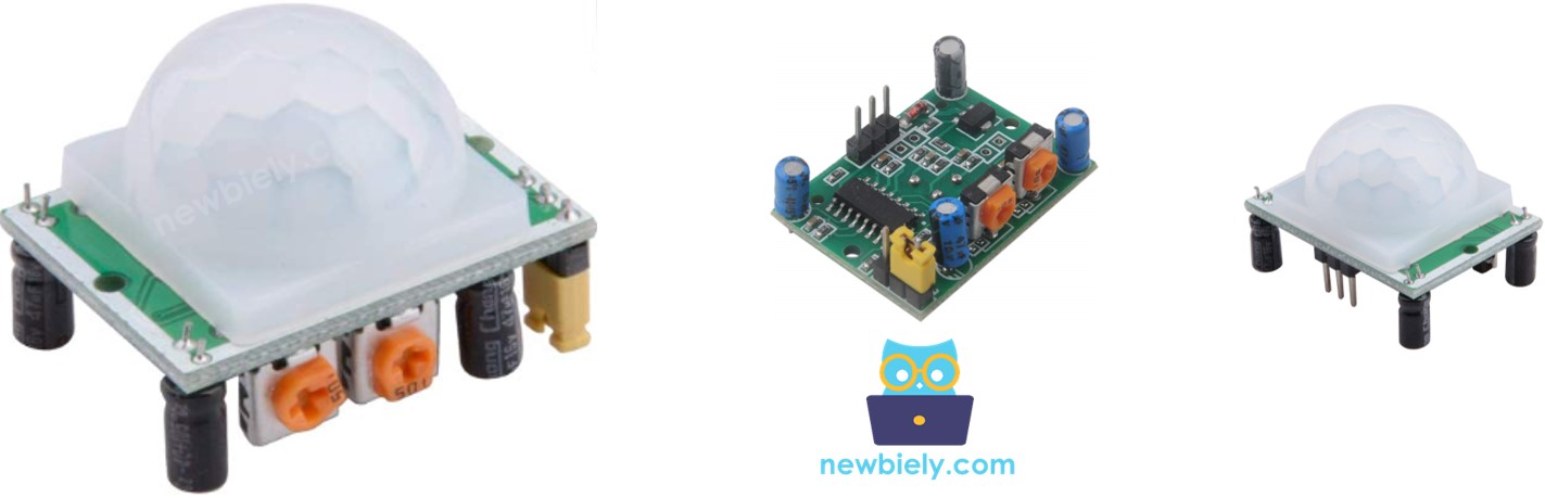
For more detail about the motion sensor, see the ESP32 S3 - Motion Sensor tutorial.
Key Specifications
| Item | Value |
|---|---|
| Power | 5V |
| Output | 3.3V HIGH when it sees a movement, LOW when it sees nothing |
| Distance | 3 to 7 meters (you can change it) |
| Angle | about 110° |
| Warm-up time | 30 to 60 seconds after power on |
※ NOTE THAT:
The output of the HC-SR501 is 3.3V, so you can connect it directly to an ESP32 S3 pin. It is safe.
PIR Motion Sensor Pinout
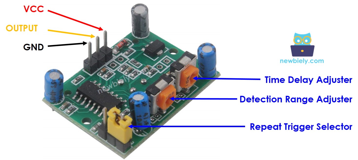
The sensor has 3 pins:
- VCC pin: connect this pin to 5V
- GND pin: connect this pin to GND
- OUT pin: goes HIGH when the sensor sees a movement
The Two Orange Screws
The HC-SR501 has two small orange screws. Turn them with a small screwdriver:
| Screw | What it changes | Turn right (clockwise) |
|---|---|---|
| Sensitivity | How far the sensor sees | Sees further (up to 7 m) |
| Time delay | How long the output stays HIGH | Stays HIGH longer (up to 5 minutes) |
※ NOTE THAT:
For this project, turn the time delay screw all the way to the left. The output then stays HIGH for only about 3 seconds, so the sensor is ready again quickly.
The Jumper with Two Positions
Next to the pins there is a small jumper:
| Position | Name | What happens |
|---|---|---|
| H | Repeat | The output stays HIGH while the movement continues |
| L | Single | The output goes HIGH one time, then LOW |
Both positions work with this code. H is the usual choice.
How The Project Works
The code watches the OUT pin all the time. It does not look for "the pin is HIGH". It looks for the moment the pin changes from LOW to HIGH:
This is important. If the code only looked for HIGH, it would take a new photo hundreds of times per second while a person stands in front of the camera.
Wiring Diagram between PIR Motion Sensor and ESP32 S3
Connect the PIR motion sensor to your ESP32 S3 with three jumper wires.
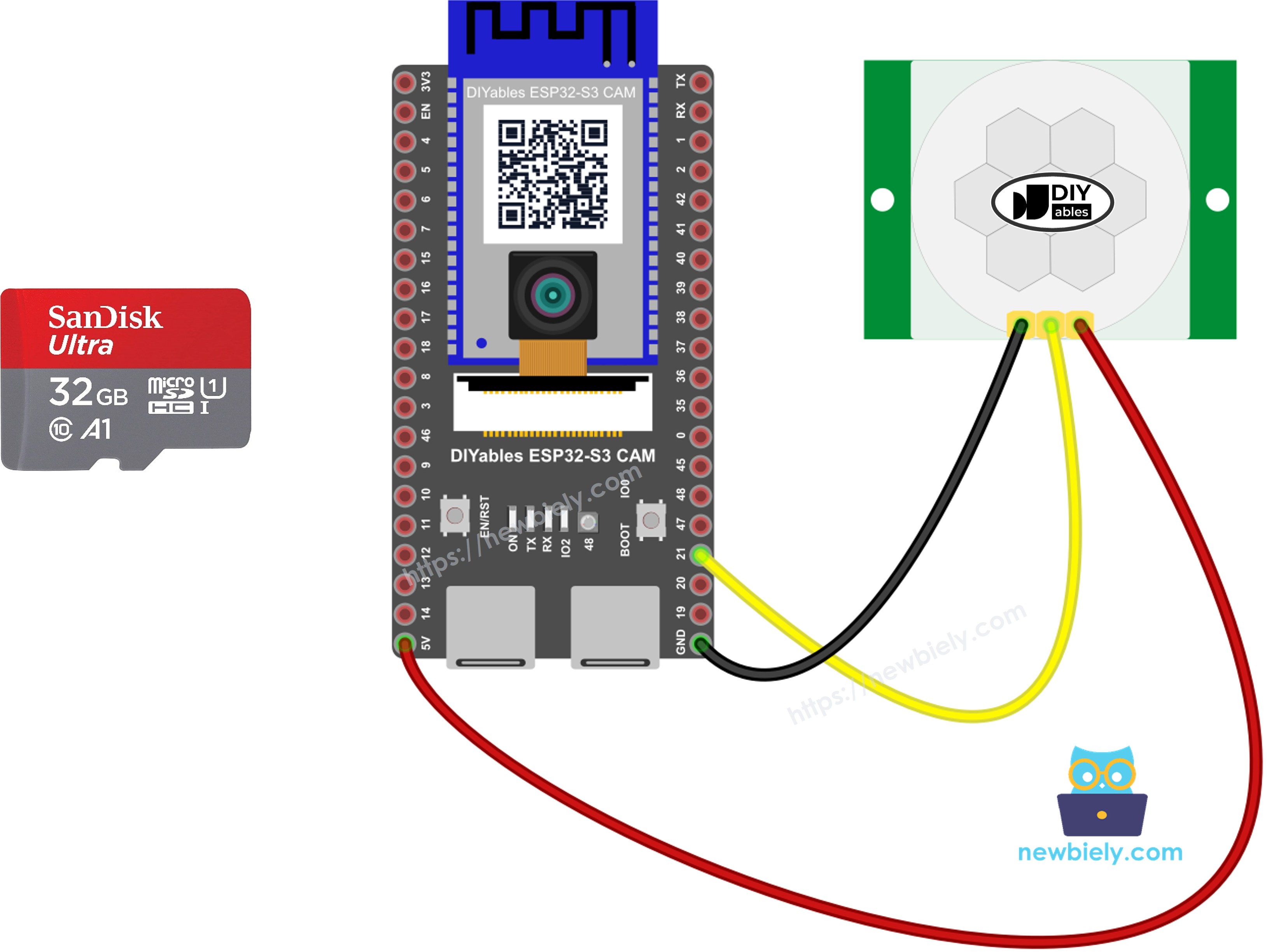
This image is created using Fritzing. Click to enlarge image
| PIR Sensor Pin | ESP32 S3 Pin |
|---|---|
| VCC | 5V |
| GND | GND |
| OUT | GPIO21 |
Then put the microSD card into the slot on the board.
Safety Notes
The PIR sensor needs 5V on its VCC pin, not 3.3V. With 3.3V it looks like it works, but it gives wrong signals. Its OUT pin gives 3.3V, which is correct for the ESP32 S3.
Do not use a camera pin for the sensor. The camera already uses GPIO4, 5, 6, 7, 8, 9, 10, 11, 12, 13, 15, 16, 17 and 18. The card slot uses GPIO38, 39 and 40. GPIO21 is free, so we use it.
Arduino IDE Settings for ESP32 S3 Camera
The camera does not work with the default settings of the Arduino IDE. You must change some items in the Tools menu before you upload the code.
| Tools Menu Item | Select This |
|---|---|
| Board | ESP32S3 Dev Module |
| Flash Size | 16MB (128Mb) |
| PSRAM | OPI PSRAM |
| Partition Scheme | Huge APP (3MB No OTA/1MB SPIFFS) |
| CPU Frequency | 240MHz (WiFi) |
| USB Mode | Hardware CDC and JTAG |
| Upload Mode | UART0 / Hardware CDC |
| Upload Speed | 921600 |
| USB CDC On Boot | Enabled |
※ NOTE THAT:
PSRAM must be OPI PSRAM, and Partition Scheme must be Huge APP. Change Flash Size first, because the list of Partition Scheme options changes after that.
How To Program the Motion Camera
- Set the sensor pin as an input.
- Wait for the sensor after you start the board. A PIR sensor needs 30 to 60 seconds to learn the heat of the room. Before that, it gives false alarms.
- Look for the moment the pin changes from LOW to HIGH.
- Add a quiet time. Without it, one person walking slowly makes ten photos.
- Save the photo to the card. This part is the same as in the ESP32 S3 Camera - Save Photo to SD Card Every Few Seconds tutorial.
ESP32 S3 Code
The following code saves a photo named motion_00001.jpg, motion_00002.jpg, and so on, every time the sensor sees a movement. The quiet time is 5 seconds. To change it, change the line #define QUIET_TIME 5000.
Detailed Instructions
- New to ESP32 S3? Complete our Getting Started with ESP32 S3 guide first.
- Format your microSD card as FAT32 on your computer.
- Unplug the USB cable. Put the card into the slot, and wire the PIR sensor as in the table above.
- Turn the time delay screw of the sensor all the way to the left.
- Copy the above code and paste it into the Arduino IDE.
- Change the settings in the Tools menu. See the table above.
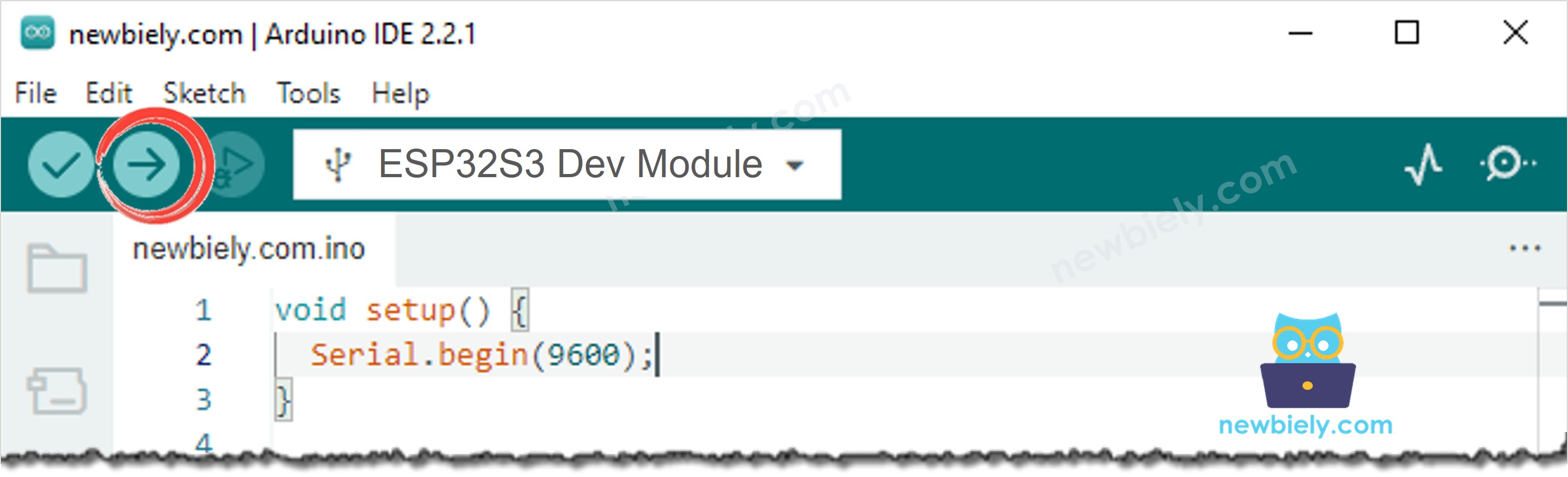
- Compile and upload the code to the ESP32 S3 board by clicking the Upload button in Arduino IDE.
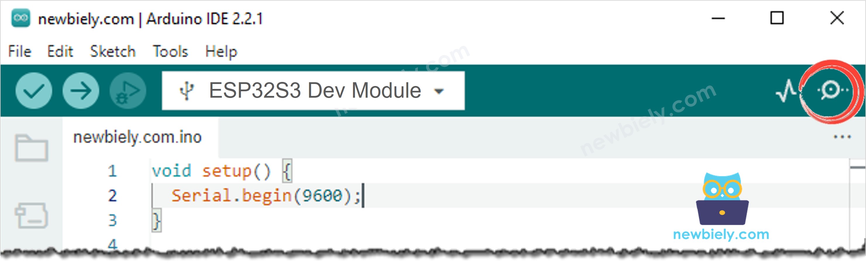
- Open the Serial Monitor in Arduino IDE.
- Press the RESET button one time, then leave the room for 30 seconds. The sensor is warming up.
- Come back and walk in front of the camera.
- Look at the Serial Monitor. You see Motion detected! and the name of the photo.
- Pro Tip: Point the sensor away from windows, heaters and air conditioners. Moving warm air makes false alarms.
Serial Monitor
The following readings were captured in 2026:
Troubleshooting
The sensor sees a movement all the time, even in an empty room.
Try these, one by one:
- Wait one full minute after you start the board. The sensor is still warming up.
- Turn the sensitivity screw a little to the left.
- Point the sensor away from windows, heaters, air conditioners and lamps.
- Check that VCC is on 5V, not on 3.3V. This is the most common mistake.
The sensor never sees anything.
- Check the wire on the OUT pin. It must go to GPIO21.
- Turn the sensitivity screw a little to the right.
- Walk across the front of the sensor, not straight towards it. A PIR sensor sees side movement much better.
One person makes five or six photos.
Increase QUIET_TIME from 5000 to 15000 (15 seconds).
The Serial Monitor shows SD card not found.
Format the card as FAT32, use a card of 32 GB or smaller, and push the card in again.
The photo is dark.
A PIR sensor also works in the dark, but the camera does not. Add a light, or a lamp that switches on with the movement.
The Serial Monitor shows nothing after the boot messages.
If your USB cable is in the port named UART, set USB CDC On Boot to Disabled. If it is in the port named USB, set it to Enabled.
Applications
This camera keeps everything on the microSD card, so it works with no WiFi, no internet and no monthly payment. Here are practical projects you can build with this code:
- Offline security camera: See who came into your room while you were away, with no internet connection at all.
- Package delivery camera: Take a photo when the delivery person arrives at your door.
- Wildlife and trail camera: Photograph cats, birds, foxes or deer in your garden or in the forest at night.
- Shop alarm record: Keep a picture of every person who enters after closing time.
- Garage and bicycle watcher: Watch your bicycle, your car or your motorbike in a garage with no WiFi.
- Holiday home camera: Leave it in an empty house for weeks, and read the card when you come back.
- Building site camera: Keep a photo of everybody who enters the site outside working hours.
- Farm and field camera: Watch a gate or a barn far away from any router.
- Classroom science project: Show students how a sensor, a camera and a memory card work together.
- Backup for a WiFi camera: Keep photos on the card even when the internet is down.
Video Tutorial
Watch the step-by-step video walkthrough for this ESP32 S3 project below.
Challenges
- Beginner: Add an LED that turns on for two seconds every time a photo is saved.
- Intermediate: Save three photos in a row on every movement, so you see the direction of the person.
- Advanced: Write a text file on the card with one line per event, for example the photo name and the time since the board started.