
ESP32 S3 - Water Sensor
Learn how to interface a water level sensor with your ESP32 S3 to detect water leakage, rainfall, tank overflow, and measure water levels in this beginner-friendly Arduino tutorial.
What you'll build:
- A water level reader that outputs raw analog values to Serial Monitor
- A water leakage detector that lights an LED when water is present
- A multi-level water depth monitor categorizing levels from empty to high
- A calibrated sensor setup for accurate real-world water level measurements
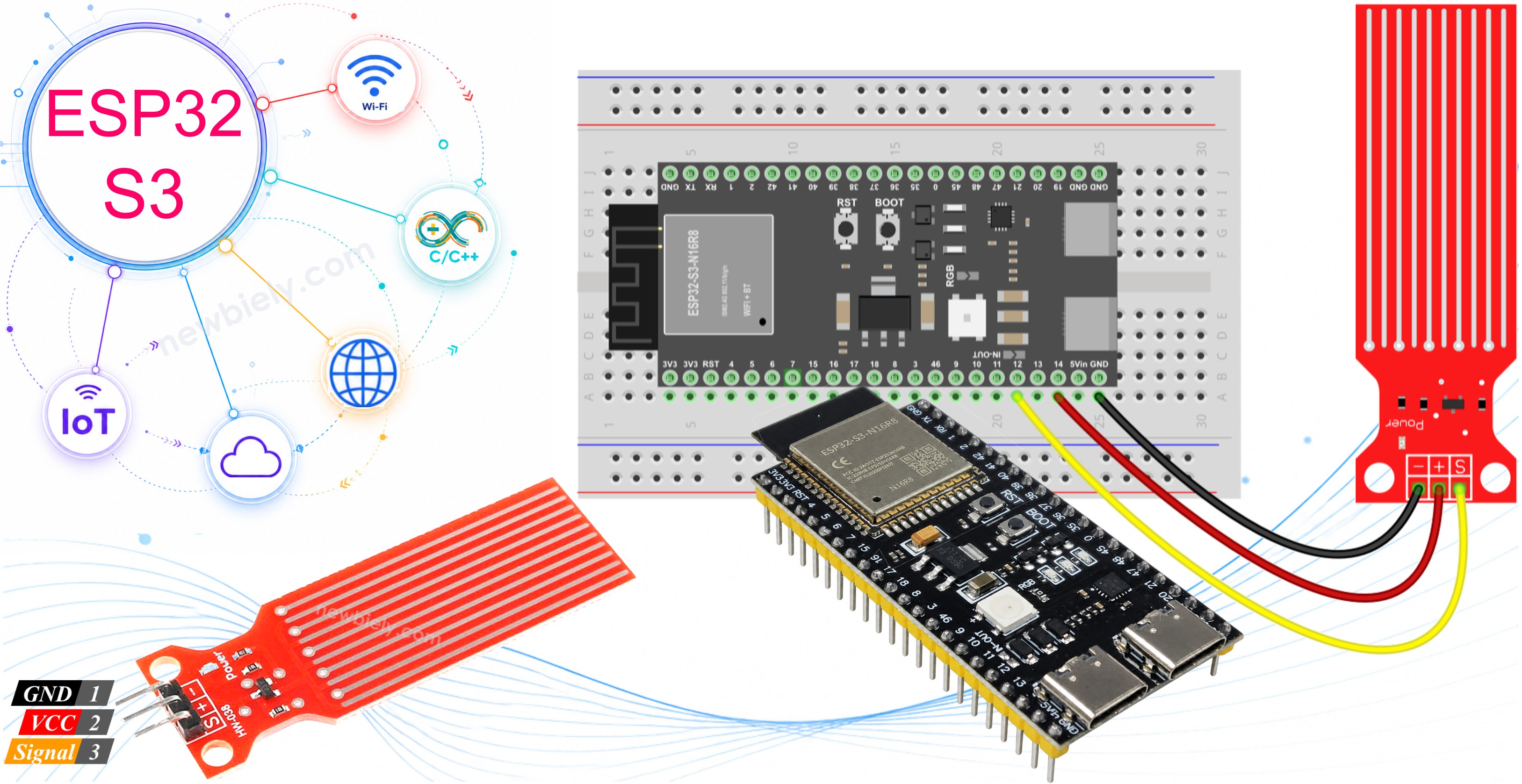
Hardware Preparation
Or you can buy the following kits:
| 1 | × | DIYables ESP32 S3 Starter Kit (ESP32 S3 included) | |
| 1 | × | DIYables Sensor Kit (18 sensors/displays) |
Additionally, some of these links are for products from our own brand, DIYables .
Overview of Water Level Sensor
A water level sensor is an analog sensor that detects the presence and depth of water by measuring resistance between exposed conductive traces on its PCB. As water bridges more of these traces, electrical resistance decreases and the output voltage rises proportionally. This makes it straightforward to pair with the ESP32 S3's built-in ADC for a range of water detection and measurement applications.
Key Specifications
The sensor operates on either 3.3V or 5V, making it directly compatible with the ESP32 S3's logic levels without any level-shifting circuitry. It exposes three pins — Signal, VCC, and GND — and outputs an analog voltage that scales with the depth of water contact. The sensing area consists of alternating conductive traces; only this exposed region should be immersed in water, keeping the onboard electronics dry at all times.
Water Level Sensor Pinout
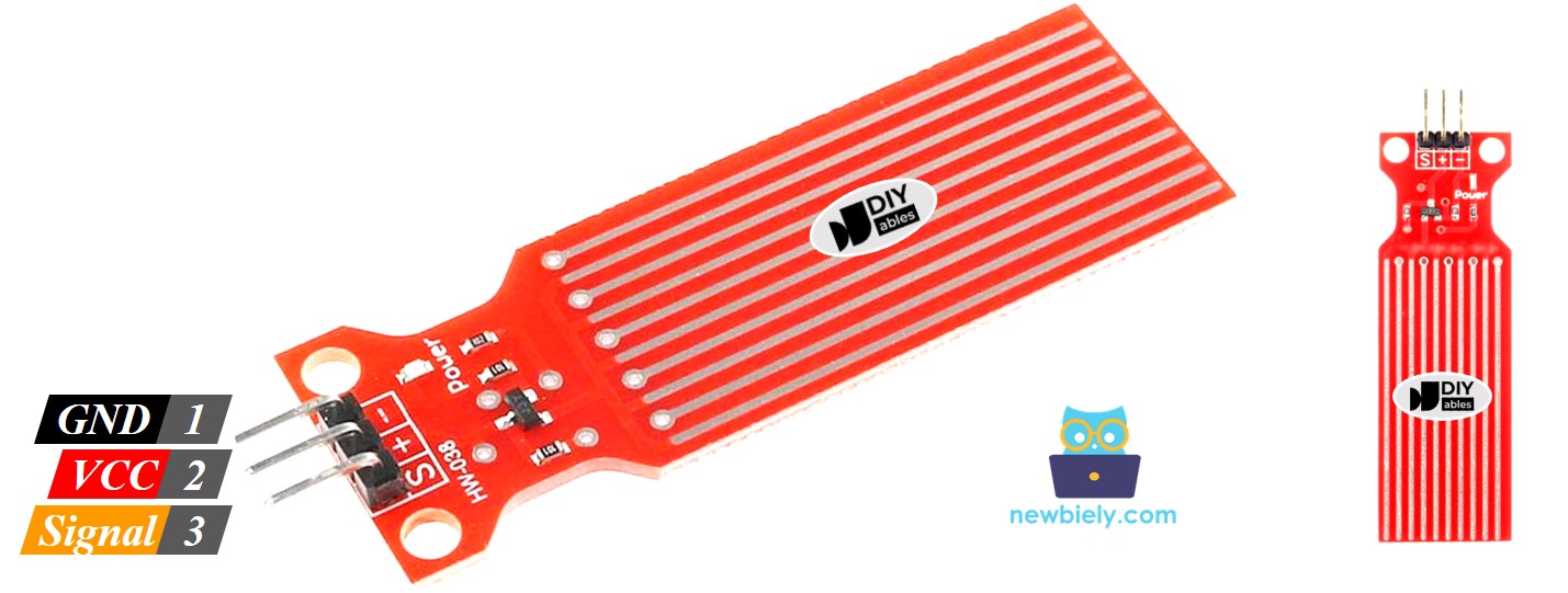
The water level sensor has three pins for connection to your ESP32 S3.
- S (Signal) pin: Outputs an analog voltage proportional to the water level — connect to an ESP32 S3 analog input pin
- + (VCC) pin: Power supply pin — connect to 3.3V or a GPIO configured as a digital output for power-managed readings
- - (GND) pin: Ground reference — connect to GND
How Water Level Sensor Works
The sensor operates on the principle of variable electrical conductivity. When the exposed traces are dry, almost no current flows between them, producing a near-zero output voltage. As water rises and covers progressively more traces, conductivity increases and the output voltage climbs toward the supply rail. The ESP32 S3 reads this varying analog voltage through its ADC and converts it to a numeric value that reflects the current water depth.
Wiring Diagram
Connect the water sensor to your ESP32 S3 carefully to ensure reliable readings and long sensor lifespan. Because constant power causes electrochemical corrosion on the exposed traces, the VCC pin should be driven by a GPIO output rather than a permanent 3.3V rail — this way the firmware can cut power between readings.
Safety Notes
Power the sensor's VCC pin from a digital GPIO output pin rather than from the board's 3.3V pin. Enable that GPIO only for the brief moment needed to take a reading, then pull it low immediately afterward. Never submerge the sensor beyond the exposed trace region; the PCB electronics and the connector end must remain completely dry at all times.
| Water Sensor Pin | ESP32 S3 Pin |
|---|---|
| S (Signal) | GPIO12 (Analog Input) |
| + (VCC) | GPIO14 (Digital Output for Power Control) |
| * (GND) | GND |
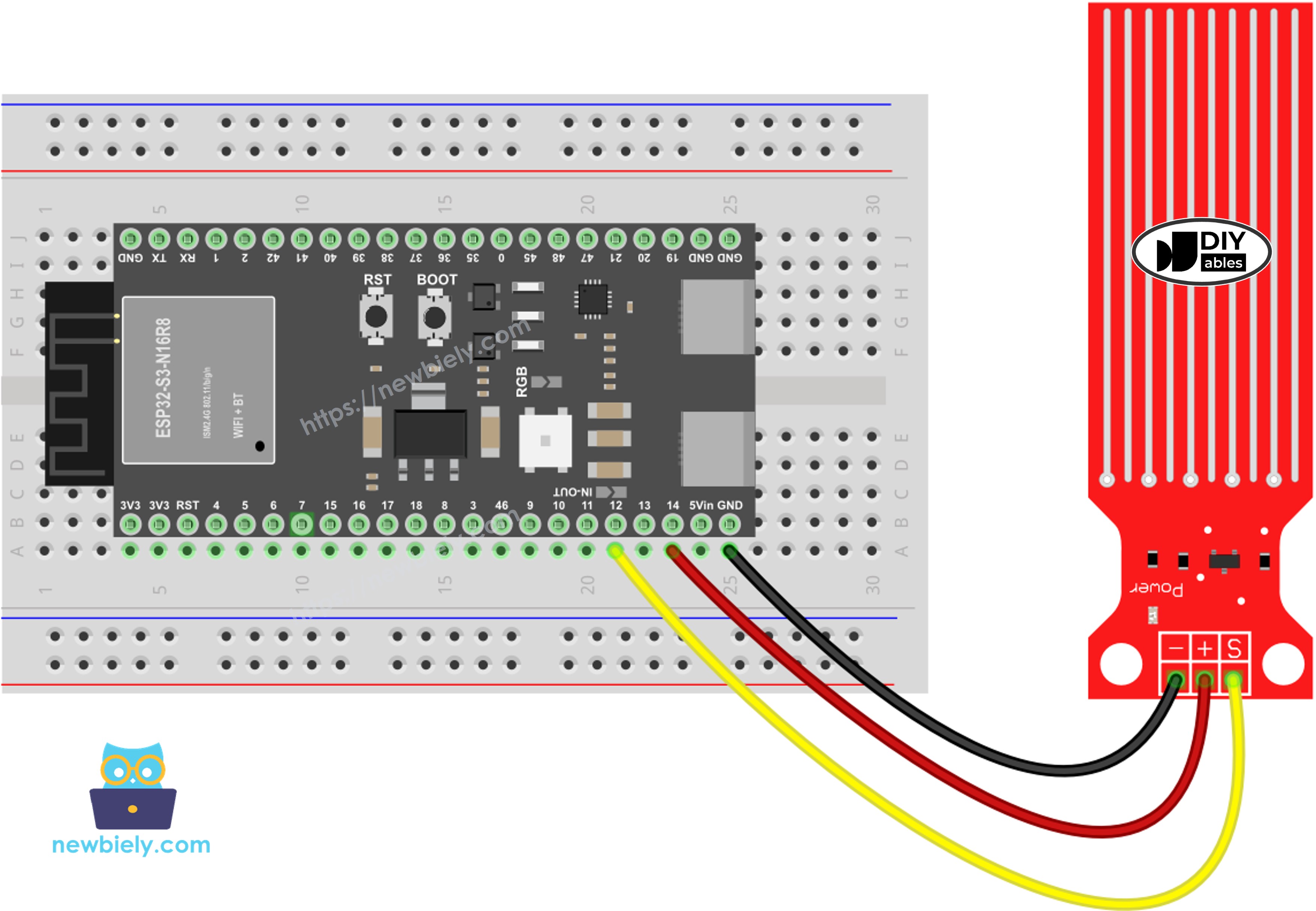
This image is created using Fritzing. Click to enlarge image
ESP32 S3 Code - Reading Value from Water Sensor
The following code reads the raw analog value from the water sensor on your ESP32 S3 and prints it to the Serial Monitor. It controls power to the sensor via a digital GPIO pin, energising the sensor only during the measurement window to minimise electrochemical corrosion on the exposed traces. After taking a reading the firmware immediately cuts power, keeping the sensor in good condition for longer-term deployments.
Detailed Instructions
- New to ESP32 S3? Complete our Getting Started with ESP32 S3 guide first.
- Wire the sensor to the ESP32 S3 following the table in the Wiring Diagram section above.
- Copy the code above and paste it into the Arduino IDE.
- Select your ESP32 S3 board and the correct COM port under the Tools menu.
- Click the Upload button to compile and flash the sketch to your board.
- Prepare a glass or bowl of water for sensor testing.
- Open the Serial Monitor and set the baud rate to 115200.
- Slowly dip the sensing traces into the water, starting from the bottom, and watch the values climb.
- Observe that values return toward zero when you lift the sensor out of the water.
- Pro Tip: Keep the sensor's PCB electronics and connector completely above the waterline — only the exposed conductive traces at the tip should contact water.
※ NOTE THAT:
The water sensor is not designed to be completely submerged. Only the exposed traces on the PCB should contact water. Please install and test the sensor carefully to avoid damaging the electronics.
How To Detect Water Leakage
Water leakage detection works by comparing the sensor's analog reading against a threshold value established during calibration. When the reading exceeds the threshold the firmware treats that as a leak event and can trigger an alert — in this example, a visible LED indicator. This pattern is the foundation for more sophisticated leak detection systems such as Wi-Fi notifications or automated shut-off valves.
Wiring Diagram
| Component | ESP32 S3 Pin |
|---|---|
| Water Sensor S | GPIO12 (Analog Input) |
| Water Sensor + | GPIO14 (Digital Output) |
| Water Sensor - | GND |
| LED Anode (+) | GPIO4 (through 220Ω resistor) |
| LED Cathode (-) | GND |
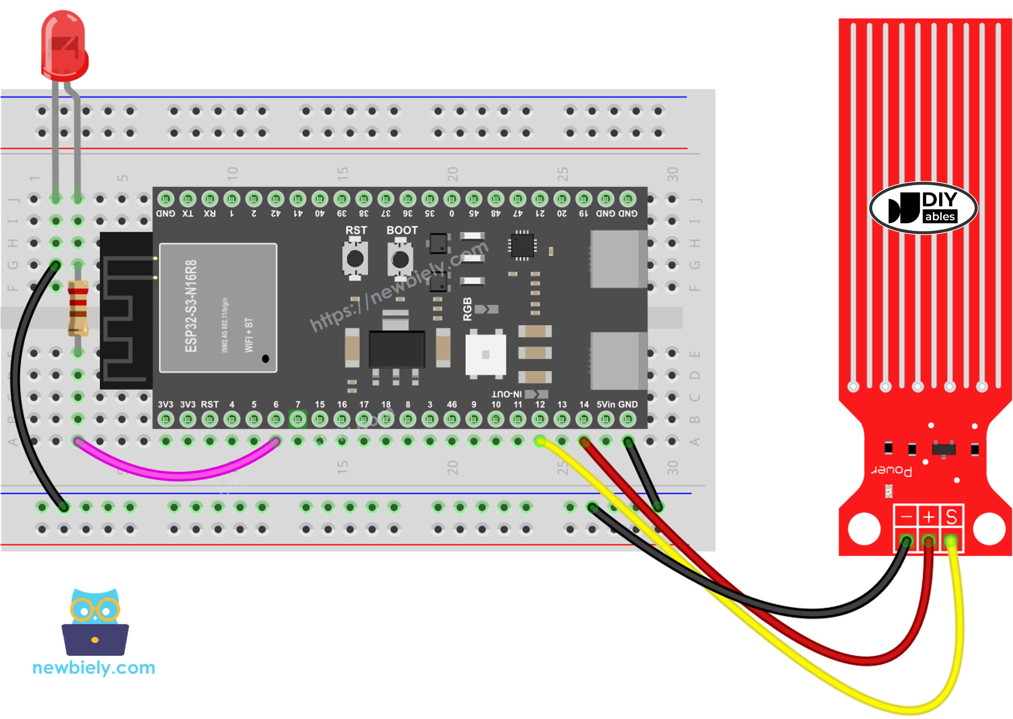
This image is created using Fritzing. Click to enlarge image
ESP32 S3 Code - Detecting Water Leakage
The following code continuously monitors the water sensor and compares each reading to a configured threshold. When the sensor value rises above that threshold the ESP32 S3 switches the LED on to signal a leak; when the value drops back below the threshold the LED turns off. The current detection status is also printed to the Serial Monitor so you can observe the system's response in real time.
How To Measure The Water Level
This example divides the full measurement range into four named categories — Empty, Low, Medium, and High — to give human-readable depth information rather than a raw numeric value. The firmware maps the calibrated sensor range onto these four levels and prints the current level name to the Serial Monitor each time a reading is taken.
※ NOTE THAT:
- SENSOR_MIN and SENSOR_MAX are determined by the calibration process described in the section below.
- The linear mapping method used here is not perfectly precise, but it is acceptable for most practical applications.
Water Level Sensor Calibration
Accurate water level readings require calibrating the sensor against your specific setup because raw ADC values vary between individual sensors and ESP32 S3 boards. Record the output value when the traces are completely dry — this is SENSOR_MIN — then immerse just the trace region fully and record the maximum value as SENSOR_MAX. Enter both constants into your sketch to make the mapping functions work correctly for your environment.
See how to calibrate the water level sensor
※ NOTE THAT:
This tutorial uses the analogRead() function to read values from an ADC (Analog-to-Digital Converter). The ESP32 S3's built-in ADC is adequate for projects that do not require high accuracy. For projects that need precise measurements, keep the following in mind:
- The ESP32 S3's ADC is not perfectly linear and may require calibration for accurate results. Each individual board can vary slightly, so calibration should be performed per board.
- ADC calibration can be challenging for beginners and may not yield perfect precision in all cases.
For applications requiring high precision, consider pairing the ESP32 S3 with an external ADC such as the ADS1115. If you wish to calibrate the ESP32 S3's internal ADC, refer to the ESP32 ADC Calibration Driver.
Application Ideas
The combination of an ESP32 S3 and a water level sensor opens the door to a wide range of practical monitoring and automation projects.
- Basement flood detector: Alerts a smartphone via Wi-Fi the moment water is detected on the floor.
- Automatic plant watering system: Monitors soil moisture or reservoir level and triggers a pump as needed.
- Aquarium water level monitor: Detects evaporation and activates an auto-refill valve to maintain a safe water line.
- DIY rain gauge: Measures accumulated rainfall depth for a home weather station.
- Coffee maker drip tray alert: Prevents overflow by warning when the drip tray approaches capacity.
- Sump pump monitor: Detects pump failure by watching for rising water that should have been evacuated.
Video Tutorial
Watch the step-by-step video walkthrough for this ESP32 S3 project below.
Challenge Yourself
Now that your water sensor is working, push the project further by taking on one of these progressively harder challenges.
- Beginner: Add a buzzer that beeps when water is detected above the threshold.
- Beginner: Display the water level as a percentage of the calibrated range on the Serial Monitor instead of the raw ADC value.
- Intermediate: Build a Wi-Fi-enabled leak detector that sends an email or push notification when water is detected.
- Intermediate: Create a multi-sensor system that monitors several locations simultaneously and reports each one individually.
- Advanced: Design an automatic water tank filling system that uses upper and lower level sensors to control a relay-driven pump.
- Advanced: Build a data logging system that records water level readings over time and displays a trend graph on a web dashboard served by the ESP32 S3.