
ESP32 S3 - Touch Sensor
This tutorial instructs you how to use the ESP32 S3 with a touch sensor (also known as a touch switch or touch button). By the end, you will be able to detect touch events in real time and print the sensor state to the Serial Monitor.
What you'll build:
- A circuit connecting a touch sensor to the ESP32 S3
- Code that reads the touch sensor state using digitalRead()
- Serial Monitor output showing LOW/HIGH state changes
- A state-change detector that triggers only on the rising edge of a touch event
Hardware Preparation
Or you can buy the following kits:
| 1 | × | DIYables ESP32 S3 Starter Kit (ESP32 S3 included) | |
| 1 | × | DIYables Sensor Kit (18 sensors/displays) |
Additionally, some of these links are for products from our own brand, DIYables .
Overview of Touch Sensor
A touch sensor detects the presence of a human finger through capacitive sensing, making it an intuitive alternative to mechanical buttons. When touched, the sensor's SIGNAL pin outputs a HIGH state; when released, it returns to LOW. This predictable behavior makes it straightforward to integrate with the ESP32 S3's digital input pins.
Key Specifications
Touch Sensor Pinout
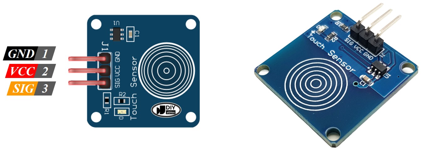
Touch sensor has 3 pins:
- GND pin: connect this pin to GND (0V)
- VCC pin: connect this pin to VCC (5V or 3.3V)
- SIGNAL pin: is an output pin — LOW when NOT touched, HIGH when touched. This pin needs to be connected to the ESP32 S3's input pin.
How Touch Sensor Works
- The state of the SIGNAL pin is LOW when the touch sensor is NOT touched
- The state of the SIGNAL pin is HIGH when the touch sensor is touched
ESP32 S3 - Touch Sensor
We can connect the touch sensor's SIGNAL pin to an ESP32 S3 input pin and use the ESP32 S3 code to read the state of the touch sensor.
Wiring Diagram between Touch Sensor and ESP32 S3
Connect the touch sensor to the ESP32 S3 by linking the sensor's GND to board GND, VCC to 3.3V, and the SIGNAL pin to a GPIO input pin such as GPIO8. Double-check all connections before powering the board to avoid damage.
Safety Notes
Always connect the GND wire first and disconnect it last when working with the circuit. Ensure the VCC voltage matches the touch sensor's rated input voltage — most modules support both 3.3V and 5V, but verify the datasheet before applying power.
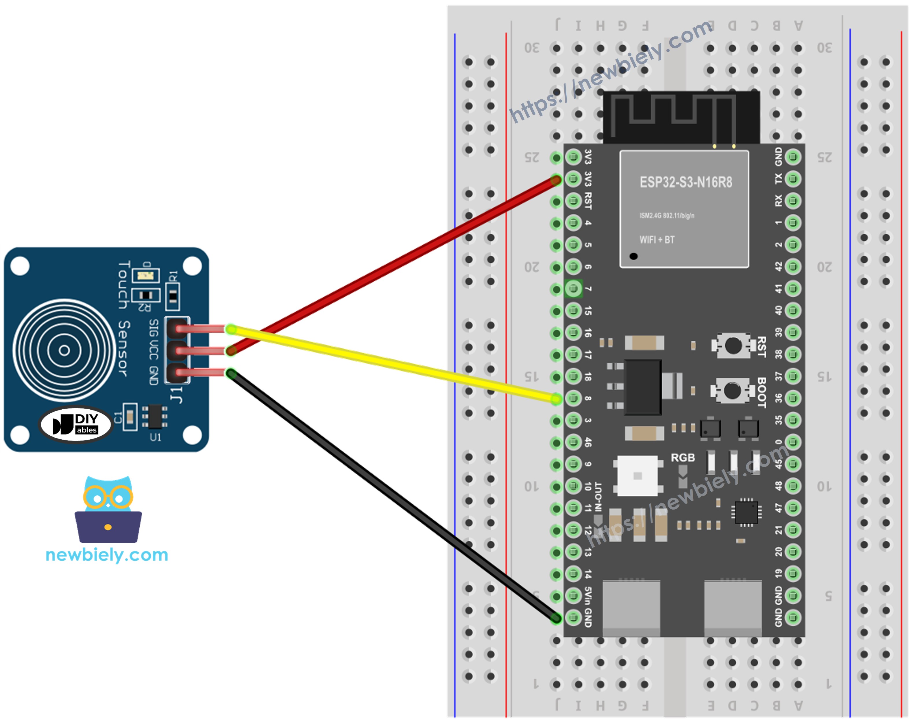
This image is created using Fritzing. Click to enlarge image
How To Program Touch Sensor
Programming the ESP32 S3 to read a touch sensor involves two steps: configuring the GPIO pin as an input and then polling its state inside the main loop. The following snippets show each step individually before the full sketch ties them together.
- Initializes the ESP32 S3 pin to the digital input mode by using pinMode() function. For example, pin GPIO8
- Reads the state of the ESP32 S3 pin by using digitalRead() function.
Touch Sensor - ESP32 S3 Code
The following code reads the state of the touch sensor and prints it to the Serial Monitor. It continuously polls GPIO8 and outputs a 0 when the sensor is not touched and a 1 when it is touched, letting you observe changes in real time.
Detailed Instructions
- New to ESP32 S3? Complete our Getting Started with ESP32 S3 guide first.
- Copy the above code and paste it to Arduino IDE.
- Compile and upload code to the ESP32 S3 board by clicking Upload button on Arduino IDE.
- Touch your finger to the sensor and release.
- See the result on Serial Monitor. It looks like the below:
- Pro Tip: Try touching the sensor pad lightly versus firmly — the capacitive sensor responds to even a gentle finger contact, making it ideal for touch-sensitive UI designs.
How to detect the state change from LOW to HIGH
The following code detects only the rising-edge transition — the moment the touch sensor changes from not touched to touched — so your program reacts once per touch rather than continuously while the finger remains on the pad.
Applications
Touch sensors are widely used in modern electronics wherever a sleek, buttonless interface is desired. Here are some practical use cases:
- Smart Lamp Control: Tap the base of a lamp to toggle it on or off without a physical switch.
- Touch-Based Security Panel: Use a touch pad as part of a PIN-entry system for door locks.
- Interactive Display: Trigger animations or screen transitions in a kiosk or museum exhibit.
- Kitchen Timer: Build a touch-activated countdown timer that avoids mechanical wear in humid environments.
- Capacitive Keyboard: Chain multiple touch sensors together to create a custom input device.
Video Tutorial
Watch the step-by-step video walkthrough for this ESP32 S3 project below.
Challenges
Push your skills further by extending the basic touch sensor project in new directions. Each challenge below builds on the foundation you have already established.
- Beginner: Modify the code so an LED connected to GPIO2 turns on when the touch sensor is touched and turns off when released.
- Intermediate: Use the state-change detection sketch to count the total number of touches and display the count on the Serial Monitor.
- Advanced: Combine two touch sensors so that touching both simultaneously triggers a special event, such as activating a buzzer for two seconds.