
ESP32 S3 - Traffic Light

This tutorial shows you how to use the ESP32 S3 to control a traffic light module. You will learn how to wire the module, program the ESP32 S3 to cycle through traffic light states, and then optimize the code using functions and the non-blocking millis() approach.

What you'll build:

  1. Wire a traffic light module to the ESP32 S3 board
  2. Program the ESP32 S3 to cycle red, yellow, and green lights in sequence
  3. Refactor the code using a dedicated control function for cleaner logic
  4. Implement a non-blocking version using millis() instead of delay()
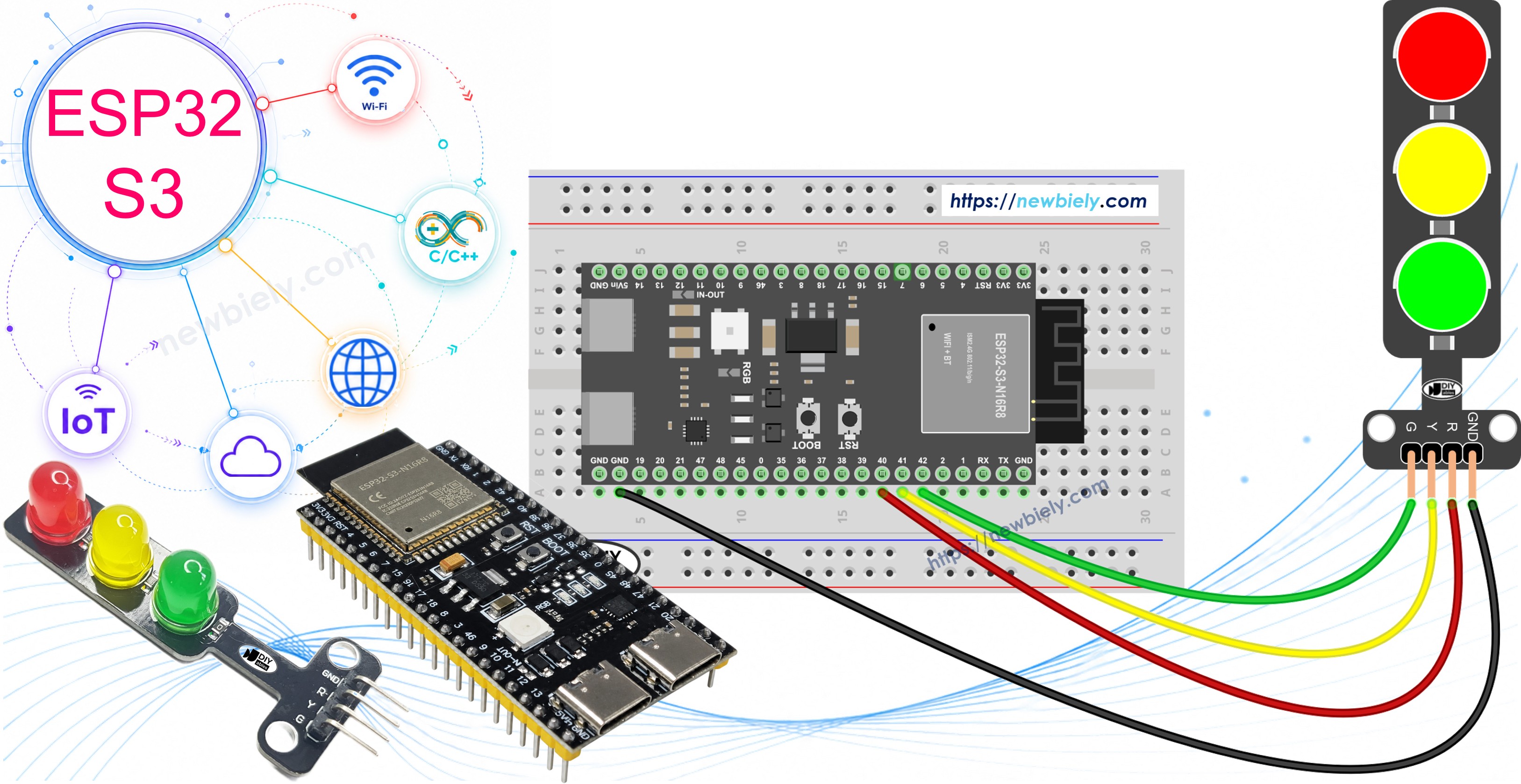
ESP32 S3 Traffic Light

Hardware Preparation

1×ESP32 S3 WROOM N16R8
1×USB Cable Type-A to Type-C (for USB-A PC)
1×USB Cable Type-C to Type-C (for USB-C PC)
1×Traffic Light Module
1×Jumper Wires

Or you can buy the following kits:

1×DIYables Sensor Kit (18 sensors/displays)
Disclosure: Some of the links provided in this section are Amazon affiliate links. We may receive a commission for any purchases made through these links at no additional cost to you.
Additionally, some of these links are for products from our own brand, DIYables .

Overview of Traffic Light Module

A traffic light module integrates three colored LEDs — red, yellow, and green — into a single compact package that is easy to wire and program. It is commonly used in embedded projects to simulate intersection signals, teach sequencing logic, and demonstrate GPIO output control on microcontrollers like the ESP32 S3. The module handles current limiting internally, so no external resistors are required.

Key Specifications

  • Operating voltage: 3.3V–5V (compatible with ESP32 S3 GPIO output)
  • Pins: GND, R (red), Y (yellow), G (green)
  • Built-in current-limiting resistors for each LED

Pinout

A traffic light module includes 4 pins:

  • GND pin: The ground pin, connect this pin to GND of ESP32 S3.
  • R pin: The pin to control the red light, connect this pin to a digital output of ESP32 S3.
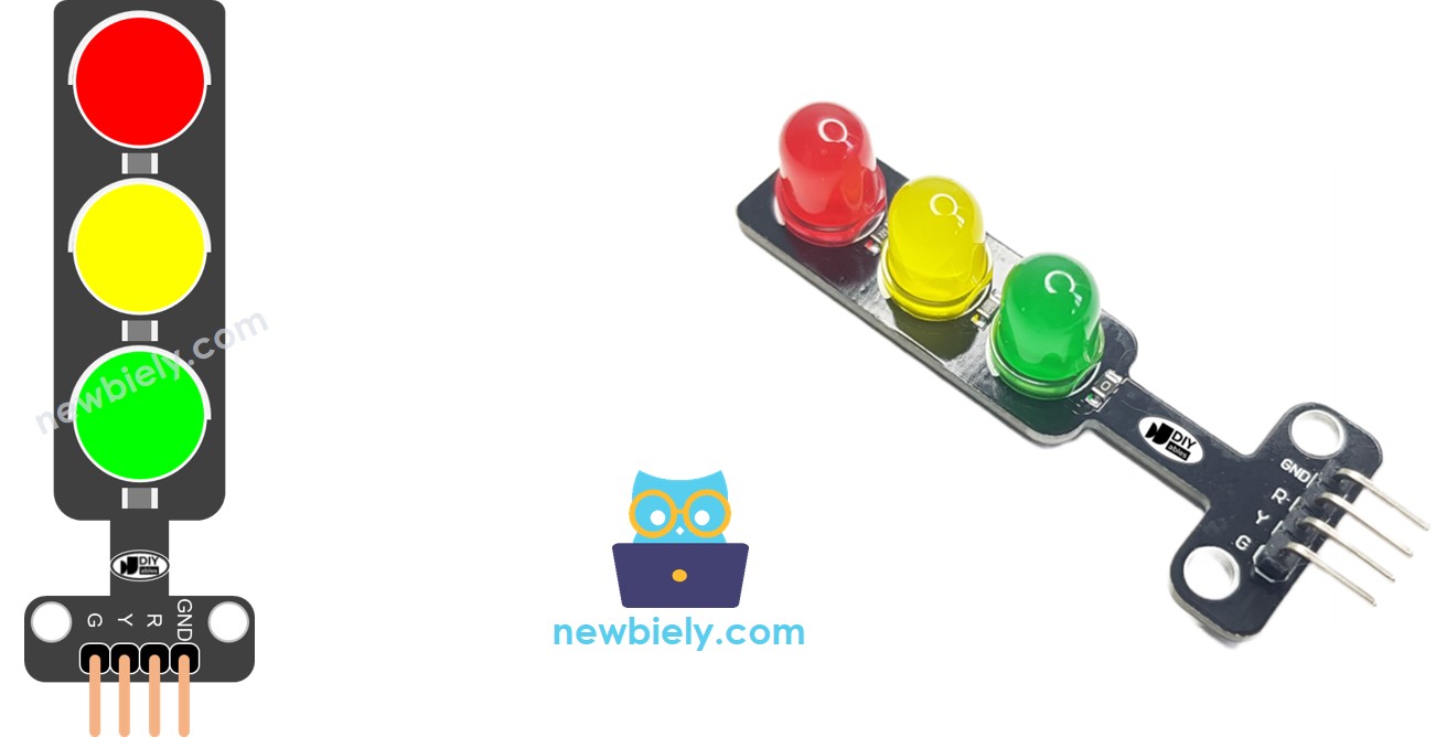
  • Y pin: The pin to control the yellow light, connect this pin to a digital output of ESP32 S3.
  • G pin: The pin to control the green light, connect this pin to a digital output of ESP32 S3.
Traffic Light Pinout

Wiring Diagram

Connect the traffic light module to the ESP32 S3 by linking each signal pin (R, Y, G) to a separate GPIO output pin and the GND pin to any ground on the board. Use jumper wires to make a clean and reliable connection between the module and the ESP32 S3 headers.

Safety Notes

The traffic light module includes built-in current-limiting resistors, so no additional resistors are needed between the module and the ESP32 S3 GPIO pins. Keep the wiring tidy and double-check GND connectivity before powering the board to avoid erratic LED behavior.
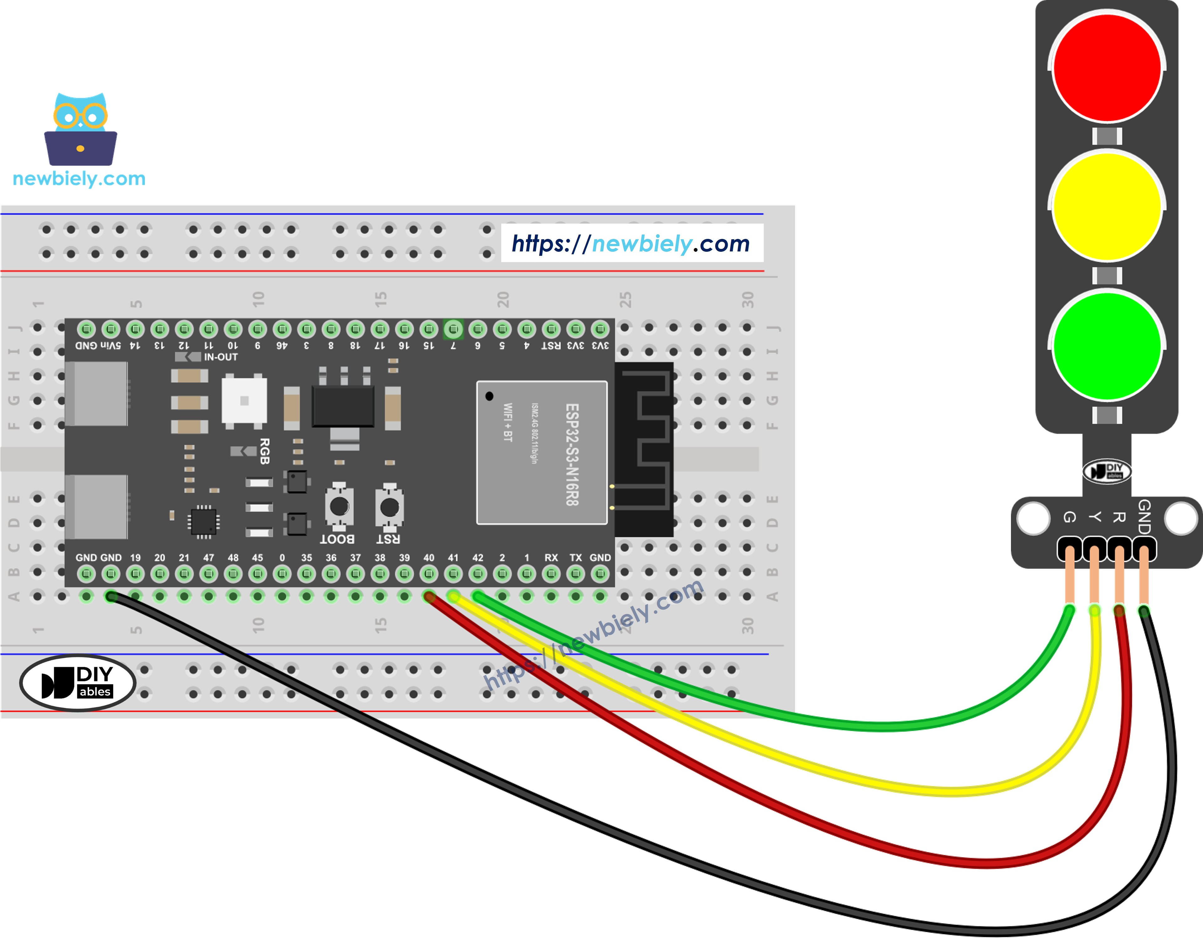
The wiring diagram between ESP32 S3 traffic light

This image is created using Fritzing. Click to enlarge image

GPIO Pin Traffic Light Module
GPIO 40 R (Red)
GPIO 41 Y (Yellow)
GPIO 42 G (Green)
GND GND

How To Program For Traffic Light Module

  • Configure the ESP32 S3's pins to digital output mode by using the pinMode() function
pinMode(PIN_RED, OUTPUT); pinMode(PIN_YELLOW, OUTPUT); pinMode(PIN_GREEN, OUTPUT);
digitalWrite(PIN_RED, HIGH); // turn on RED digitalWrite(PIN_YELLOW, LOW); digitalWrite(PIN_GREEN, LOW); delay(RED_TIME); // keep red LED on during a period of time

ESP32 S3 Code

The following code demonstrates how to control the traffic light module with the ESP32 S3 using straightforward digitalWrite() calls and delay() for timing. Each stage of the traffic cycle — red, yellow, and green — is activated in turn by setting the appropriate pin HIGH while holding the others LOW. Upload this code to your ESP32 S3 board to see the traffic light sequence run immediately after boot.

/* * This ESP32 S3 code was developed by newbiely.com * * This ESP32 S3 code is made available for public use without any restriction * * For comprehensive instructions and wiring diagrams, please visit: * https://newbiely.com/tutorials/esp32-s3/esp32-s3-traffic-light */ /* * This ESP32-S3 code is created by esp32io.com * * This ESP32-S3 code is released in the public domain * * For more detail (instruction and wiring diagram), visit https://esp32io.com/tutorials/esp32-s3-traffic-light */ #define PIN_RED 40 // The ESP32-S3 pin GPIO40 connected to R pin of traffic light module #define PIN_YELLOW 41 // The ESP32-S3 pin GPIO41 connected to Y pin of traffic light module #define PIN_GREEN 42 // The ESP32-S3 pin GPIO42 connected to G pin of traffic light module #define RED_TIME 4000 // RED time in millisecond #define YELLOW_TIME 4000 // YELLOW time in millisecond #define GREEN_TIME 4000 // GREEN time in millisecond void setup() { pinMode(PIN_RED, OUTPUT); pinMode(PIN_YELLOW, OUTPUT); pinMode(PIN_GREEN, OUTPUT); } // the loop function runs over and over again forever void loop() { // red light on digitalWrite(PIN_RED, HIGH); // turn on digitalWrite(PIN_YELLOW, LOW); // turn off digitalWrite(PIN_GREEN, LOW); // turn off delay(RED_TIME); // keep red light on during a period of time // yellow light on digitalWrite(PIN_RED, LOW); // turn off digitalWrite(PIN_YELLOW, HIGH); // turn on digitalWrite(PIN_GREEN, LOW); // turn off delay(YELLOW_TIME); // keep yellow light on during a period of time // green light on digitalWrite(PIN_RED, LOW); // turn off digitalWrite(PIN_YELLOW, LOW); // turn off digitalWrite(PIN_GREEN, HIGH); // turn on delay(GREEN_TIME); // keep green light on during a period of time }

Detailed Instructions

  1. New to ESP32 S3? Complete our Getting Started with ESP32 S3 guide first.
  2. Do the wiring as shown in the diagram above.
  3. Connect the ESP32 S3 board to your PC via a USB Type-C cable.
  4. Open Arduino IDE on your PC.
  5. Select the right ESP32 S3 board (e.g. ESP32S3 Dev Module) and COM port.
  6. Copy the above code and paste it into Arduino IDE.
  7. Click Upload button on Arduino IDE to upload code to ESP32 S3.
  8. Observe the traffic light module cycling through red, yellow, and green.
  9. Pro Tip: Adjust the RED_TIME, YELLOW_TIME, and GREEN_TIME constants at the top of the sketch to simulate different intersection timings used in your region.

It's important to note that the exact workings of a traffic light can vary depending on the specific design and technology used in different regions and intersections. The principles described above provide a general understanding of how traffic lights operate to manage traffic and enhance safety on the roads.

The code above demonstrates individual light control. Now, let's enhance the code for better optimization.

ESP32 S3 Code Optimization

  • Let's improve the code by implementing a function for light control.
/* * This ESP32 S3 code was developed by newbiely.com * * This ESP32 S3 code is made available for public use without any restriction * * For comprehensive instructions and wiring diagrams, please visit: * https://newbiely.com/tutorials/esp32-s3/esp32-s3-traffic-light */ /* * This ESP32-S3 code is created by esp32io.com * * This ESP32-S3 code is released in the public domain * * For more detail (instruction and wiring diagram), visit https://esp32io.com/tutorials/esp32-s3-traffic-light */ #define PIN_RED 40 // The ESP32-S3 pin GPIO40 connected to R pin of traffic light module #define PIN_YELLOW 41 // The ESP32-S3 pin GPIO41 connected to Y pin of traffic light module #define PIN_GREEN 42 // The ESP32-S3 pin GPIO42 connected to G pin of traffic light module #define RED_TIME 2000 // RED time in millisecond #define YELLOW_TIME 1000 // YELLOW time in millisecond #define GREEN_TIME 2000 // GREEN time in millisecond #define RED 0 // Index in array #define YELLOW 1 // Index in array #define GREEN 2 // Index in array const int pins[] = { PIN_RED, PIN_YELLOW, PIN_GREEN }; const int times[] = { RED_TIME, YELLOW_TIME, GREEN_TIME }; void setup() { pinMode(PIN_RED, OUTPUT); pinMode(PIN_YELLOW, OUTPUT); pinMode(PIN_GREEN, OUTPUT); } // the loop function runs over and over again forever void loop() { // red light on trafic_light_on(RED); delay(times[RED]); // keep red light on during a period of time // yellow light on trafic_light_on(YELLOW); delay(times[YELLOW]); // keep yellow light on during a period of time // green light on trafic_light_on(GREEN); delay(times[GREEN]); // keep green light on during a period of time } void trafic_light_on(int light) { for (int i = RED; i <= GREEN; i++) { if (i == light) digitalWrite(pins[i], HIGH); // turn on else digitalWrite(pins[i], LOW); // turn off } }
  • Let's improve the code by using a for loop.
/* * This ESP32 S3 code was developed by newbiely.com * * This ESP32 S3 code is made available for public use without any restriction * * For comprehensive instructions and wiring diagrams, please visit: * https://newbiely.com/tutorials/esp32-s3/esp32-s3-traffic-light */ /* * This ESP32-S3 code is created by esp32io.com * * This ESP32-S3 code is released in the public domain * * For more detail (instruction and wiring diagram), visit https://esp32io.com/tutorials/esp32-s3-traffic-light */ #define PIN_RED 40 // The ESP32-S3 pin GPIO40 connected to R pin of traffic light module #define PIN_YELLOW 41 // The ESP32-S3 pin GPIO41 connected to Y pin of traffic light module #define PIN_GREEN 42 // The ESP32-S3 pin GPIO42 connected to G pin of traffic light module #define RED_TIME 2000 // RED time in millisecond #define YELLOW_TIME 1000 // YELLOW time in millisecond #define GREEN_TIME 2000 // GREEN time in millisecond #define RED 0 // Index in array #define YELLOW 1 // Index in array #define GREEN 2 // Index in array const int pins[] = {PIN_RED, PIN_YELLOW, PIN_GREEN}; const int times[] = {RED_TIME, YELLOW_TIME, GREEN_TIME}; void setup() { pinMode(PIN_RED, OUTPUT); pinMode(PIN_YELLOW, OUTPUT); pinMode(PIN_GREEN, OUTPUT); } // the loop function runs over and over again forever void loop() { for (int light = RED; light <= GREEN; light ++) { trafic_light_on(light); delay(times[light]); // keep light on during a period of time } } void trafic_light_on(int light) { for (int i = RED; i <= GREEN; i ++) { if (i == light) digitalWrite(pins[i], HIGH); // turn on else digitalWrite(pins[i], LOW); // turn off } }
  • Let's improve the code by using millis() function instead of delay().
/* * This ESP32 S3 code was developed by newbiely.com * * This ESP32 S3 code is made available for public use without any restriction * * For comprehensive instructions and wiring diagrams, please visit: * https://newbiely.com/tutorials/esp32-s3/esp32-s3-traffic-light */ /* * This ESP32-S3 code is created by esp32io.com * * This ESP32-S3 code is released in the public domain * * For more detail (instruction and wiring diagram), visit https://esp32io.com/tutorials/esp32-s3-traffic-light */ #define PIN_RED 40 // The ESP32-S3 pin GPIO40 connected to R pin of traffic light module #define PIN_YELLOW 41 // The ESP32-S3 pin GPIO41 connected to Y pin of traffic light module #define PIN_GREEN 42 // The ESP32-S3 pin GPIO42 connected to G pin of traffic light module #define RED_TIME 2000 // RED time in millisecond #define YELLOW_TIME 1000 // YELLOW time in millisecond #define GREEN_TIME 2000 // GREEN time in millisecond #define RED 0 // Index in array #define YELLOW 1 // Index in array #define GREEN 2 // Index in array const int pins[] = { PIN_RED, PIN_YELLOW, PIN_GREEN }; const int times[] = { RED_TIME, YELLOW_TIME, GREEN_TIME }; unsigned long last_time = 0; int light = RED; // start with RED light void setup() { pinMode(PIN_RED, OUTPUT); pinMode(PIN_YELLOW, OUTPUT); pinMode(PIN_GREEN, OUTPUT); trafic_light_on(light); last_time = millis(); } // the loop function runs over and over again forever void loop() { if ((millis() - last_time) > times[light]) { light++; if (light >= 3) light = RED; // new circle trafic_light_on(light); last_time = millis(); } // TO DO: your other code } void trafic_light_on(int light) { for (int i = RED; i <= GREEN; i++) { if (i == light) digitalWrite(pins[i], HIGH); // turn on else digitalWrite(pins[i], LOW); // turn off } }

Serial Monitor Output

Open the Serial Monitor at 9600 baud to observe runtime messages from the ESP32 S3. The following are example readings you might see during operation:

Newbiely | Arduino IDE 2.3.8
──
File
Edit
Sketch
Tools
Help
ESP32S3 Dev Module
Newbiely.ino
···
8 Serial.println("Hello World!");
Output
Serial Monitor
Message (Enter to send message to 'ESP32S3 Dev Module' on 'COM15')
New Line
9600 baud
[2026-06-16 10:00:00] Traffic light started [2026-06-16 10:00:00] RED ON [2026-06-16 10:00:05] YELLOW ON [2026-06-16 10:00:07] GREEN ON
Ln 11, Col 1
ESP32S3 Dev Module on COM15
2

Applications

Controlling a traffic light module with the ESP32 S3 teaches sequencing and GPIO output management skills that apply directly to many practical embedded systems. Here are some real-world use cases:

  1. Intersection Simulation: Recreate a real traffic intersection controller with configurable timing for each light phase.
  2. Industrial Status Panel: Use the three colors to represent machine states such as idle (green), warning (yellow), and fault (red).
  3. Pedestrian Crossing Signal: Add a button input to the ESP32 S3 to let a pedestrian request a green light on demand.
  4. Production Line Indicator: Signal workflow stages on an assembly line using the red, yellow, and green outputs as process state indicators.
  5. Educational Demo: Demonstrate state machine concepts and non-blocking timing techniques to students learning embedded programming.

Video Tutorial

Watch the step-by-step video walkthrough for this ESP32 S3 project below.

Challenges

Practicing variations of this project will deepen your understanding of GPIO sequencing and timing control on the ESP32 S3. Try the following exercises to extend your skills:

  1. Beginner: Change the timing constants so the yellow light stays on for 3 seconds and the green light stays on for 8 seconds, then re-upload and observe the difference.
  2. Intermediate: Add a pushbutton connected to the ESP32 S3 that, when pressed, immediately switches the light to red and holds it for 10 seconds before resuming the normal cycle.
  3. Advanced: Rewrite the traffic light controller using a finite state machine (FSM) with millis() so the sequence is fully non-blocking, allowing the ESP32 S3 to handle other tasks — such as reading a sensor — while the lights cycle independently.

※ OUR MESSAGES

  • As freelancers, We are AVAILABLE for HIRE. See how to outsource your project to us
  • Please feel free to share the link of this tutorial. However, Please do not use our content on any other websites. We invested a lot of effort and time to create the content, please respect our work!