
ESP32 S3 - Relay
Learn how to control high-voltage devices safely with your ESP32 S3 using a relay module. This tutorial shows you how to switch high-power devices like lamps, pumps, and motors using simple Arduino code.
What you'll build:
- A relay-controlled circuit connected to your ESP32 S3
- A sketch that turns a high-voltage device on and off automatically
- A system that demonstrates normally open and normally closed relay modes
- A foundation for real-world home automation and switching projects
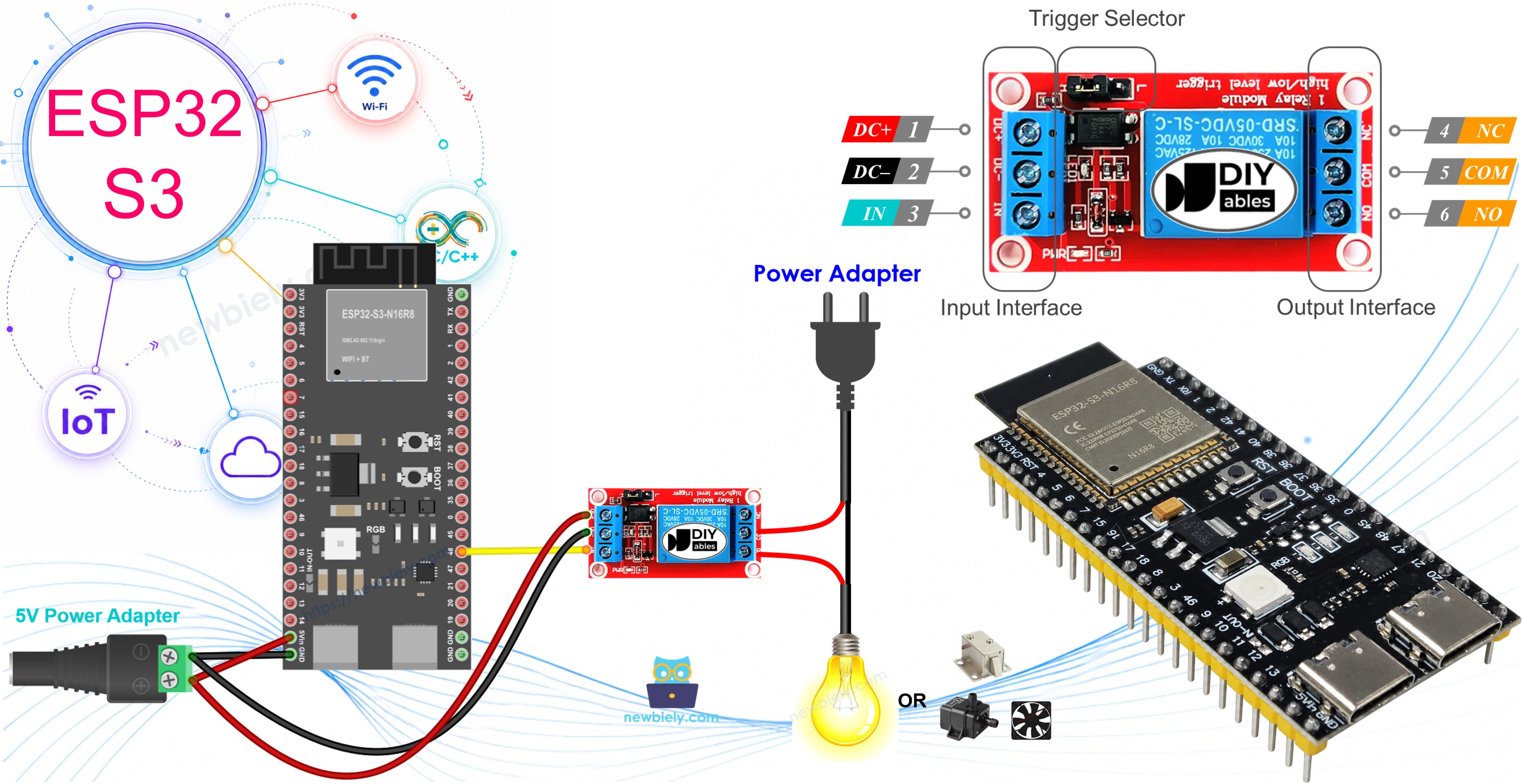
Why You Need a Relay with ESP32 S3
The ESP32 S3 digital pins operate at 3.3V and can only source a few milliamps of current, which is enough to light an LED directly but nowhere near enough to drive high-voltage devices. Connecting a lamp, pump, or motor directly to the board would instantly damage or destroy it.
A relay bridges this gap by letting your ESP32 S3 control a completely separate high-voltage circuit using nothing more than a LOW or HIGH signal on a single pin. This keeps your microcontroller safe while giving you full software control over mains-voltage or high-current loads.
Hardware Preparation
Or you can buy the following kits:
| 1 | × | DIYables ESP32 S3 Starter Kit (ESP32 S3 included) | |
| 1 | × | DIYables Sensor Kit (18 sensors/displays) |
Additionally, some of these links are for products from our own brand, DIYables .
Overview of Relay
A relay is a programmable electromechanical switch that uses a small electromagnetic coil to open or close a separate high-voltage circuit. When your ESP32 S3 drives the control pin HIGH or LOW, the coil energises, physically moving a metal contact that either completes or breaks the load circuit. Because the two circuits are electrically isolated, the ESP32 S3 is never exposed to the dangerous voltage on the load side.
Key Specifications
Most relay modules designed for microcontroller use accept a 5V coil supply and a 3.3V-compatible control signal, making them directly usable with the ESP32 S3. The output contacts are typically rated for 10 A at 250 V AC or 30 V DC, which covers the vast majority of hobbyist and light industrial applications. Relay modules usually include a flyback diode to suppress the voltage spike produced when the coil de-energises, protecting the driving pin from damage.
WARNING
Safety first! Safety first!
- Please be careful when working with high voltage. Seriously, it may shock you or even take your life. If you're NOT 100% sure what you are doing, do yourself a favor and don't touch anything. Ask someone who knows!
- Some relays can work with both DC and AC voltage, we extremely recommend you NOT to use AC voltage. Use a DC device (≤24V) only.
Relay Pinout
The relay module exposes two groups of pins: input pins that connect to your ESP32 S3 and output pins that connect to the high-voltage load.
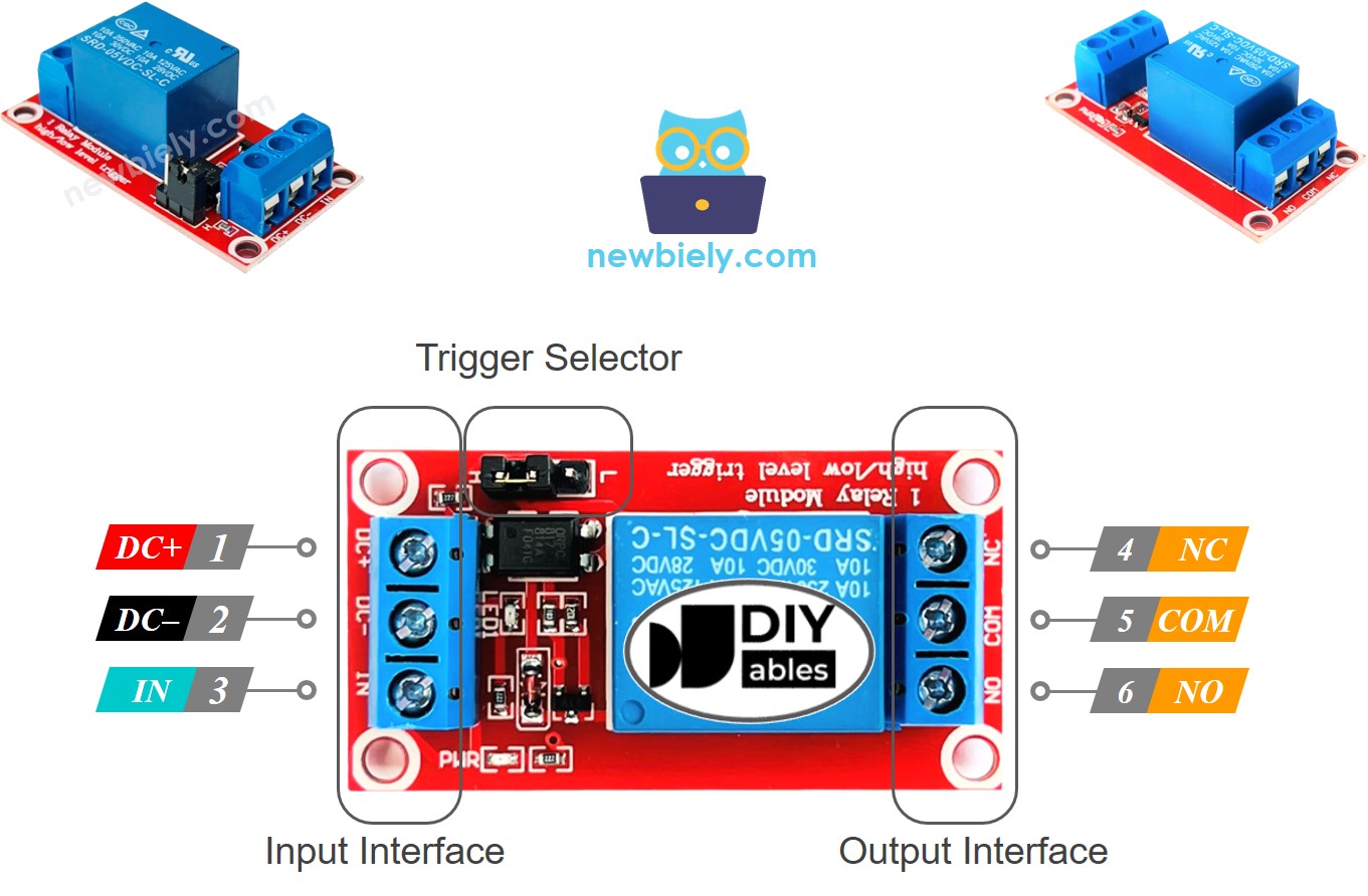
- DC- pin: Connect to GND (0V)
- DC+ pin: Connect to VCC (5V)
- IN pin: Receives the control signal from the ESP32 S3
- COM pin: Common output pin — connects to one wire of the high-voltage device
- NO pin: Normally Open output — use this for normally open mode
- NC pin: Normally Closed output — use this for normally closed mode
※ NOTE THAT:
The pin order of the relay can be different between manufacturers. Please check the labels printed on the relay carefully!
How to Connect the High-Voltage Device to Relay
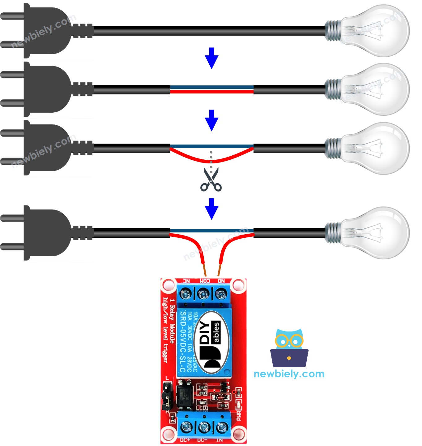
In normally open mode, connect the load between COM and NO so the circuit is open (device off) by default. In normally closed mode, connect the load between COM and NC so the circuit is closed (device on) by default. In both cases, also connect the load to its appropriate external power supply.
- Normally open mode: Use COM pin and NO pin only
- Normally closed mode: Use COM pin and NC pin only
How Relay Works
The relay module offers different operating modes based on your project needs.
Input Modes (select one):
- LOW level trigger mode: Relay activates when IN pin receives LOW (0V)
- HIGH level trigger mode: Relay activates when IN pin receives HIGH (3.3V/5V)
Output Modes (select one):
- Normally open mode: Circuit is open (OFF) when IN pin is LOW
- Normally closed mode: Circuit is closed (ON) when IN pin is LOW
Important Notes:
- The normally open and normally closed modes work oppositely
- Most relay modules support both output modes
- NOT all relay modules support both input trigger modes
- You can only use one input mode at a time (select via jumper if available)
- The "normally" term means "when IN pin is connected to LOW (0V)"
Beginner Recommendation:
- Use HIGH level trigger mode with normally open mode for easiest understanding
HIGH Level Trigger - Normally Open Mode
Connect the high-voltage device to COM pin and NO pin.
- IN pin = LOW (0V): Switch is open → Device is OFF (deactivated)
- IN pin = HIGH (5V or 3.3V): Switch is closed → Device is ON (activated)
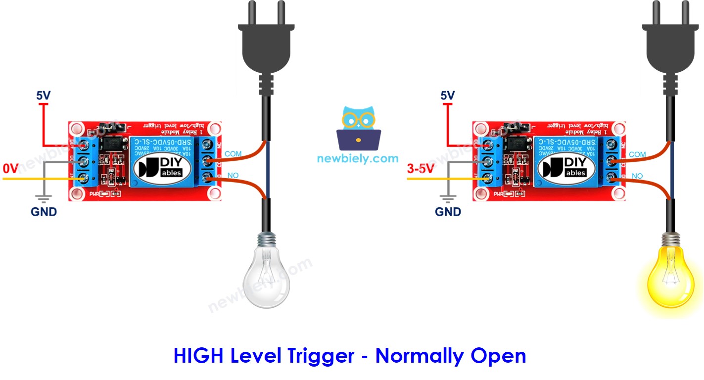
This is the most intuitive mode for beginners: the device only runs when the ESP32 S3 sends a HIGH signal to the IN pin, just like turning on a standard switch.
HIGH Level Trigger - Normally Closed Mode
Connect the high-voltage device to COM pin and NC pin.
- IN pin = LOW (0V): Switch is closed → Device is ON (activated)
- IN pin = HIGH (5V or 3.3V): Switch is open → Device is OFF (deactivated)
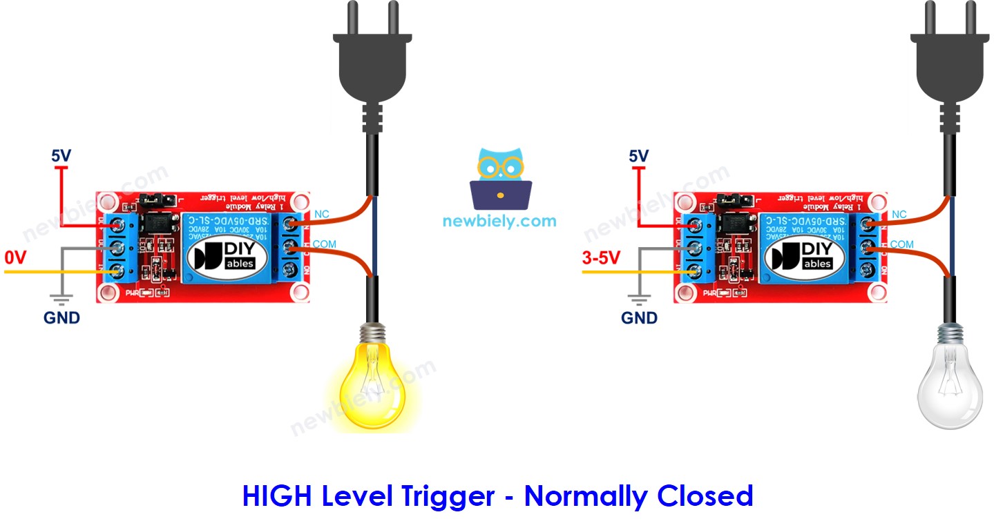
Normally closed mode works opposite to normally open: the device runs by default and the ESP32 S3 sends HIGH to turn it off. This is useful in fail-safe applications where the load must stay on if the controller loses power.
Normally Open Mode vs Normally Closed Mode
This table compares both modes when using HIGH Level Trigger:
| Mode | Pins Used | IN Pin State | Relay State | Device State |
|---|---|---|---|---|
| Normally Open | COM and NO | LOW | Open | OFF |
| Normally Open | COM and NO | HIGH | Closed | ON |
| Normally Closed | COM and NC | LOW | Closed | ON |
| Normally Closed | COM and NC | HIGH | Open | OFF |
Choose normally open for standard on/off control and normally closed for applications where the device must remain active by default.
ESP32 S3 - Relay
Controlling a relay with the ESP32 S3 requires only a single digital output pin. Connect that pin to the IN terminal of the relay module, then call digitalWrite() with HIGH or LOW to switch the load on or off. The relay handles all the high-voltage switching internally, keeping the ESP32 S3 completely isolated from the load circuit.
Wiring Diagram
The diagrams below show two common ways to power your ESP32 S3 relay project. Choose the option that best fits your setup and available hardware.
Option 1: Powering ESP32 S3 via USB port
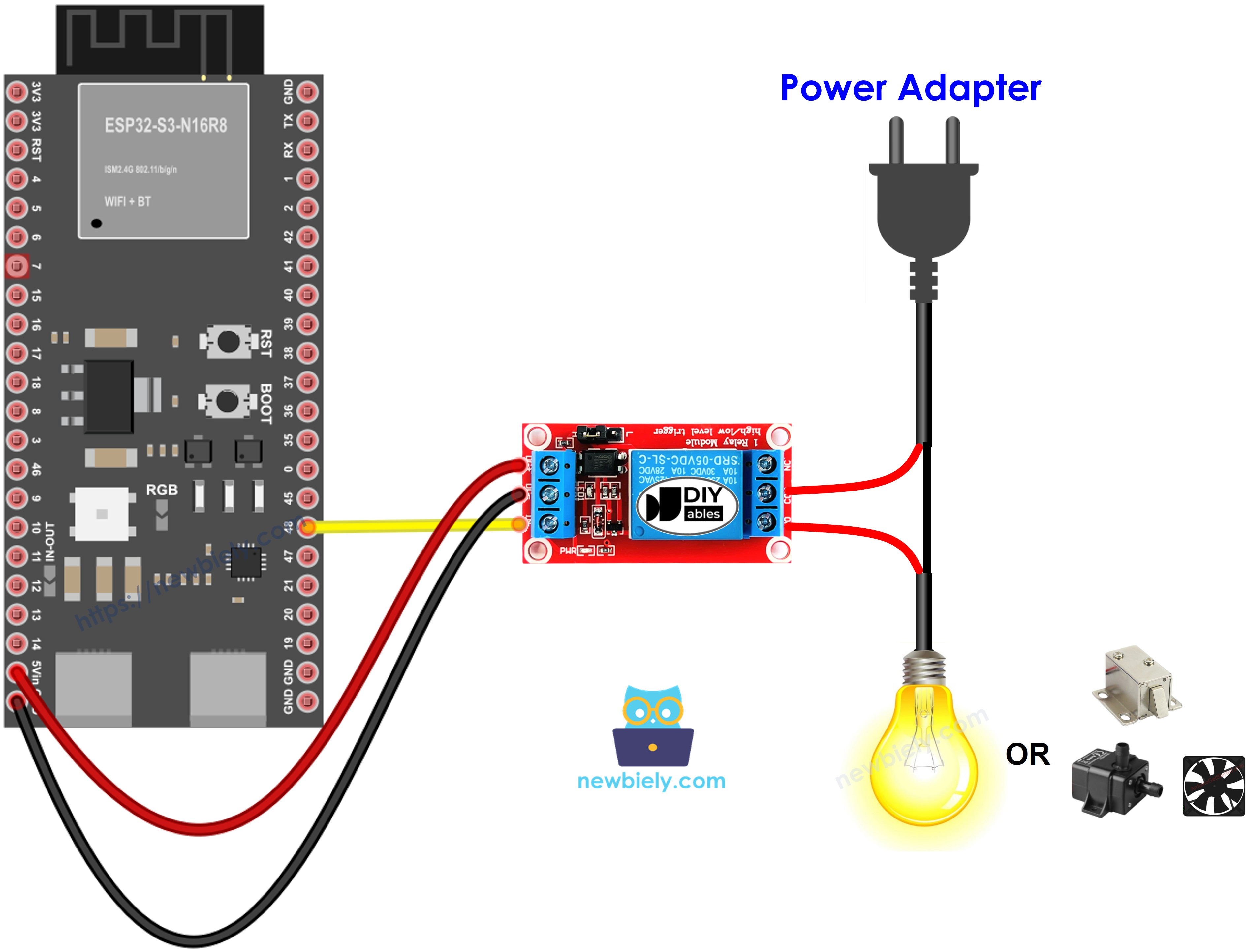
This image is created using Fritzing. Click to enlarge image
| Relay Pin | ESP32 S3 Pin |
|---|---|
| DC- | GND |
| DC+ | 5V |
| IN | GPIO48 |
| LED Strip Connection | Relay Pin |
|---|---|
| Positive (+) wire | COM |
| Negative (-) wire | NO pin |
- Note: The LED strip also requires connection to its 12V power adapter
Option 2: Powering ESP32 S3 via Vin pin
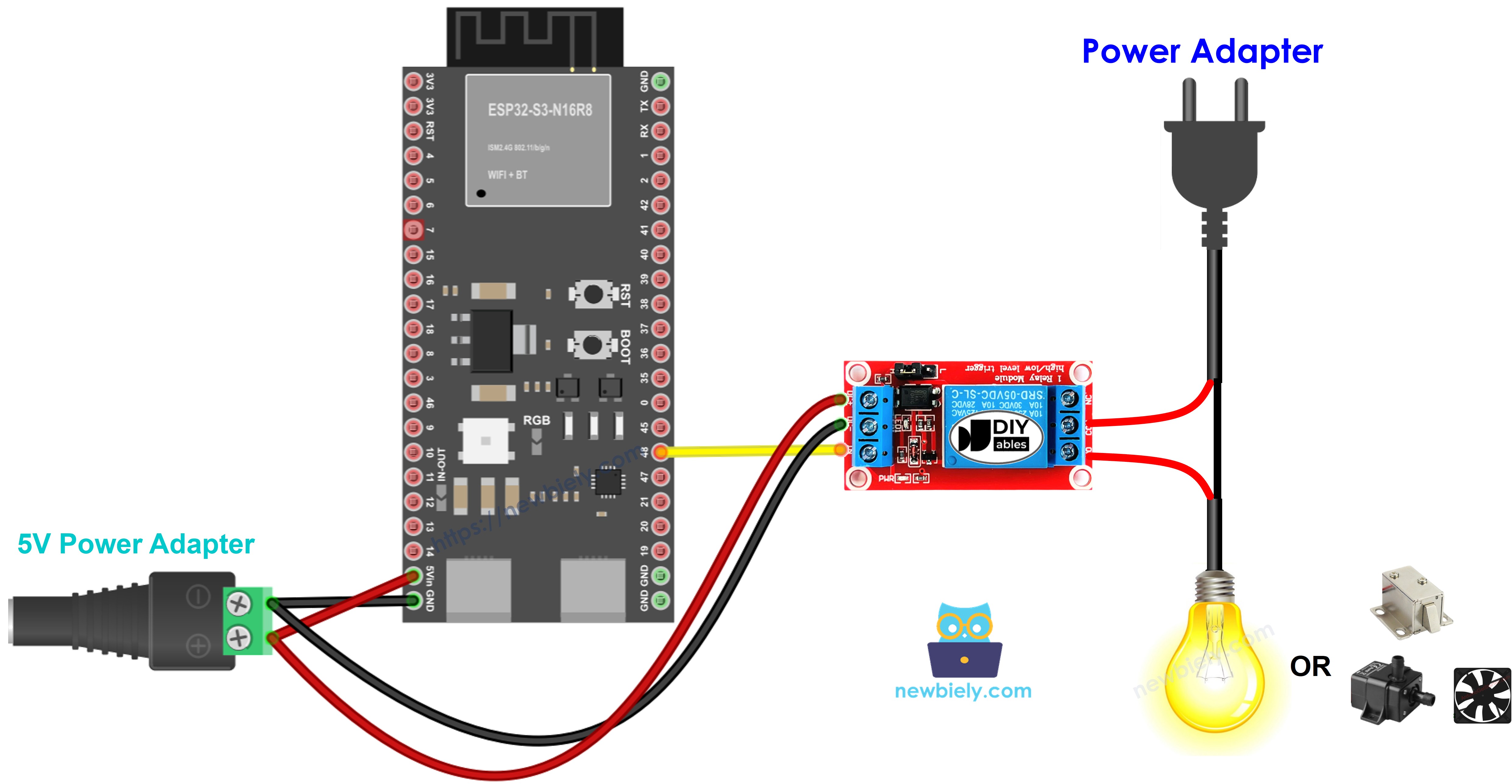
This image is created using Fritzing. Click to enlarge image
| Relay Pin | ESP32 S3 Pin |
|---|---|
| DC- | GND |
| DC+ | 5V |
| IN | GPIO48 |
- Note: Use external 12V power adapter for both ESP32 S3 (via Vin) and LED strip
Safety Notes
Always double-check all connections before applying power to any high-voltage circuit. Verify that the relay's COM and NO (or NC) terminals are securely fastened and that no bare wires are exposed. Keep the low-voltage control wiring and the high-voltage load wiring physically separated wherever possible to reduce the risk of accidental contact or short circuits.
How To Program Relay using ESP32 S3
Programming a relay with the ESP32 S3 involves three straightforward steps using standard Arduino functions. There is no external library required — everything you need is built into the Arduino core.
Step 1: Configure the pin as digital output
Step 2: Turn relay OFF (normally open mode)
Step 3: Turn relay ON (normally open mode)
ESP32 S3 Code
The following code demonstrates basic relay control with the ESP32 S3 by repeatedly toggling an LED strip on and off. It configures pin D7 as a digital output, then drives it HIGH for one second and LOW for one second in an infinite loop — creating a continuous blinking effect on whatever device is connected through the relay.
Detailed Instructions
- New to ESP32 S3? Complete our Getting Started with ESP32 S3 guide first.
- Copy the code above and paste it into Arduino IDE.
- Select your board: choose the correct ESP32 S3 board from Tools > Board menu.
- Choose your port: select the correct COM port from Tools > Port menu.
- Click the Upload button to compile and upload the sketch to the ESP32 S3.
- Watch your LED strip blink on and off every second.
- If nothing happens, double-check your relay wiring and confirm the correct trigger mode.
- Pro Tip: Add Serial.println() statements to your sketch to print the relay state to the Serial Monitor — this makes debugging wiring and logic issues much faster.
Serial Monitor Output
The relay control code does not produce Serial Monitor output by default. To monitor relay states, modify the code to include serial debugging as shown below.
Application and Project Ideas
Once you master relay control with the ESP32 S3, you can build a wide range of practical automation and smart-home projects.
- Smart home lighting: Control room lights, lamps, or LED strips automatically based on time or sensor data.
- Automated irrigation system: Turn water pumps on and off based on soil moisture sensor readings.
- Temperature-controlled fan: Activate a cooling fan when temperature exceeds a set threshold.
- Smart door lock: Control an electromagnetic lock for home security applications.
- Automatic pet feeder: Schedule feeding times by controlling a food dispenser motor.
- Garden automation: Control grow lights, ventilation fans, and watering systems on a timer.
- Remote appliance control: Turn coffee makers, heaters, or other devices on and off via WiFi using the ESP32 S3's built-in wireless capabilities.
Video Tutorial
Watch the step-by-step video walkthrough for this ESP32 S3 project below.
Challenge Yourself
Now that you can control a relay with the ESP32 S3, try these progressively challenging extensions to deepen your understanding and build more capable projects.
- Beginner: Modify the blink interval to 5 seconds on and 2 seconds off.
- Beginner: Add a push button so you can toggle the relay manually instead of relying on automatic timing.
- Intermediate: Control two relays simultaneously to switch two different devices independently.
- Intermediate: Use a temperature sensor to automatically turn a fan on when the temperature exceeds 25°C.
- Advanced: Build a WiFi-controlled relay system using the ESP32 S3's wireless interface so you can switch the load from your smartphone.
- Advanced: Create a weekly schedule that turns devices on and off at specific times each day, stored in non-volatile memory so the schedule survives power cycles.