
ESP32 S3 - TCS3200D/TCS230 Color Sensor
Learn how to connect the TCS3200D/TCS230 color sensor to your ESP32 S3 for accurate RGB color detection. This beginner-friendly tutorial covers wiring, calibration, and real-time color measurements with your ESP32 S3.
What you'll build:
- A wired connection between the TCS3200D/TCS230 color sensor and the ESP32 S3
- A calibration sketch that tracks minimum and maximum pulse widths for each color channel
- A color reading sketch that converts raw sensor data into standard RGB values (0–255)
- A Serial Monitor output showing real-time color measurements for red, green, and blue objects
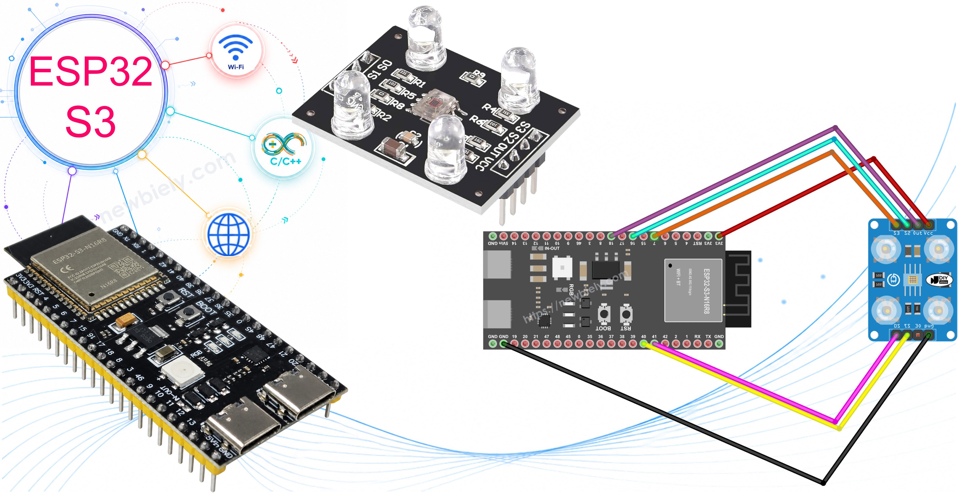
Hardware Preparation
Or you can buy the following kits:
| 1 | × | DIYables ESP32 S3 Starter Kit (ESP32 S3 included) | |
| 1 | × | DIYables Sensor Kit (18 sensors/displays) |
Additionally, some of these links are for products from our own brand, DIYables .
Overview of TCS3200D/TCS230 Color Sensor
The TCS3200D/TCS230 is an optical sensor that detects colors by measuring light reflections through specialized photodiode filters. It outputs a square wave signal whose frequency is proportional to the detected light intensity, making it straightforward to interface with the ESP32 S3's digital input pins. Its built-in white LEDs provide consistent illumination, so readings remain reliable across a variety of ambient lighting conditions.
Key Specifications
- 64 photodiodes in 8×8 array (16 red filters, 16 green, 16 blue, 16 clear)
- Frequency output proportional to light intensity
- Operating voltage: 2.7V to 5.5V (5V recommended)
- Built-in white LED illumination for consistent readings
- Output frequency range: 2 Hz to 500 kHz
- Ideal for beginners: simple digital output, no complex analog reading
Pinout
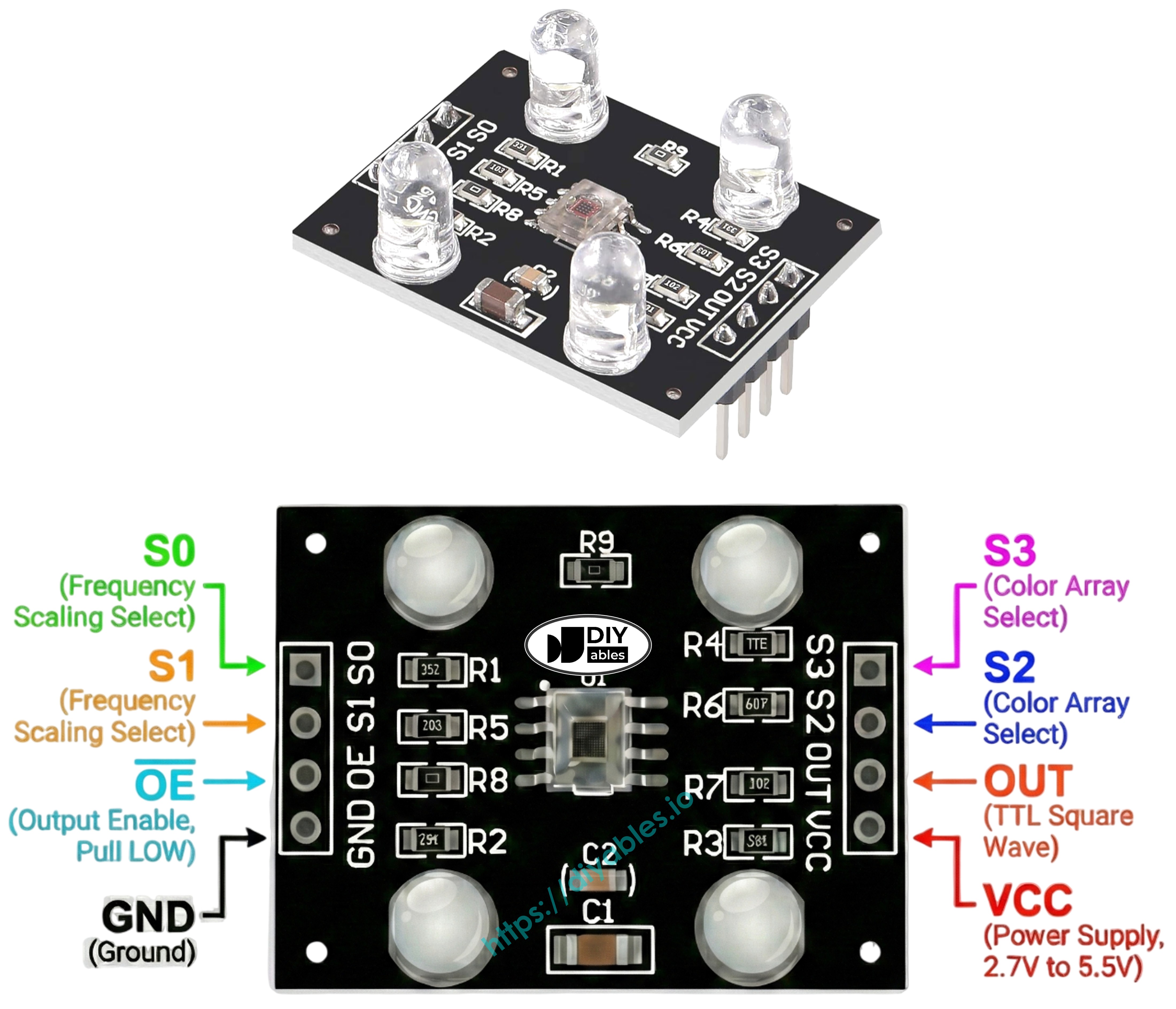
The TCS3200D/TCS230 color sensor has 8 connection pins, each serving a specific role in power, control, and signal output:
- VCC: Power supply input (connect to 5V)
- GND: Ground connection (0V reference)
- S0: Frequency scaling control pin 1
- S1: Frequency scaling control pin 2
- S2: Color filter selection pin 1
- S3: Color filter selection pin 2
- OUT: Frequency output signal pin (connect to ESP32 S3 digital pin)
- OE: Output enable pin (active LOW, usually connected to GND)
How It Works
The TCS3200 color sensor operates using two control systems:
Frequency scaling (S0 and S1 pins):
- S0=LOW, S1=LOW: Power down mode
- S0=LOW, S1=HIGH: 2% frequency scaling
- S0=HIGH, S1=LOW: 20% frequency scaling
- S0=HIGH, S1=HIGH: 100% frequency scaling (recommended)
Color filter selection (S2 and S3 pins):
- S2=LOW, S3=LOW: Red filter active
- S2=LOW, S3=HIGH: Blue filter active
- S2=HIGH, S3=LOW: Clear filter (no filtering)
- S2=HIGH, S3=HIGH: Green filter active
How readings work:
- The OUT pin outputs a square wave signal
- Frequency increases with brighter light (2 Hz to 500 kHz)
- ESP32 S3 measures pulse width using pulseIn()
- Shorter pulses = brighter light = higher color intensity
- Calibration converts pulse widths to standard RGB values (0-255)
Maximizing Measurement Precision
Follow these tips for accurate TCS3200 color readings:
- Keep sensor distance fixed at 1-3 cm from the object
- Position sensor at consistent angle (perpendicular works best)
- Use the built-in white LEDs for stable illumination
- Shield sensor from external light sources when possible
- Perform calibration in your actual working environment
- Test on flat, matte surfaces for best results
Wiring Diagram
Connect the TCS3200D color sensor to your ESP32 S3 using the pin assignments in the table below. The sensor operates at 5V, which the ESP32 S3 supplies via its 5V pin when powered over USB, so no additional power regulation is required.
Safety Notes
The TCS3200 sensor works best with 5V power, which the ESP32 S3 can provide via the 5V pin when powered through USB. Signal lines from the sensor connect directly to the ESP32 S3 digital pins without any level shifting needed for most modules, but verify your specific module's output voltage before connecting.
| TCS3200 Color Sensor | ESP32 S3 |
|---|---|
| VCC | 5V |
| GND | GND |
| S0 | GPIO41 |
| S1 | GPIO40 |
| S2 | GPIO16 |
| S3 | GPIO7 |
| OUT | GPIO18 |
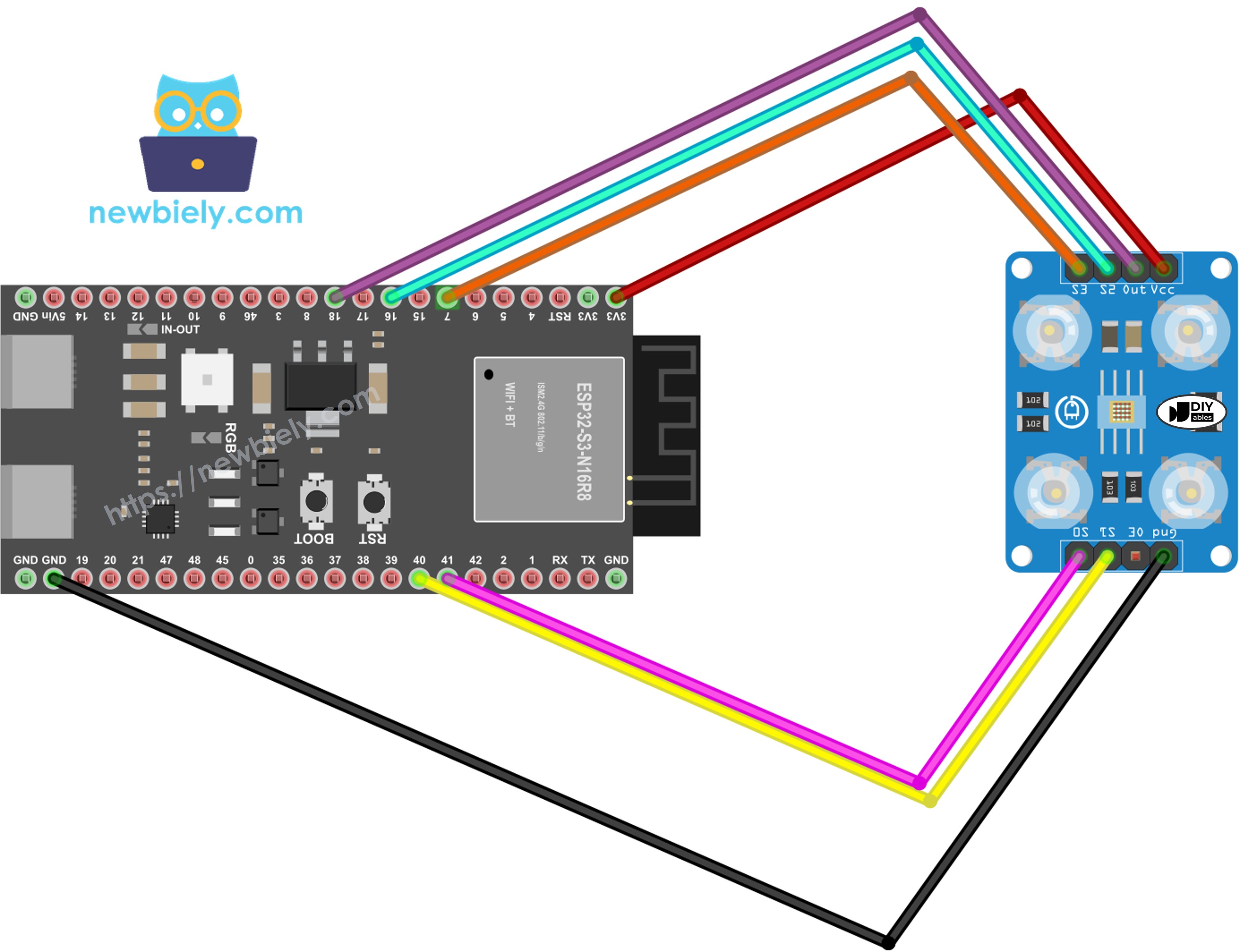
This image is created using Fritzing. Click to enlarge image
ESP32 S3 Code - Sensor Calibration
The following code sets up the TCS3200 sensor on your ESP32 S3 and guides you through a calibration process that captures the full dynamic range of your specific sensor and environment. Upload this sketch first, then expose the sensor to a variety of colors—from bright white to deep black—so it can record accurate minimum and maximum pulse-width values for each channel.
What this code does:
- Powers up the sensor with full frequency scaling (100%)
- Cycles through red, green, and blue filters
- Tracks minimum and maximum pulse widths for each color
- Continuously updates calibration values as you show different colors
- Displays real-time measurements in the Serial Monitor
Detailed Instructions
- New to ESP32 S3? Complete our Getting Started with ESP32 S3 guide first.
- Wire the components: Follow the wiring diagram above to connect all pins correctly.
- Connect your board: Plug the ESP32 S3 into your computer using a USB-C cable.
- Open Arduino IDE: Launch the software on your computer.
- Select your board: Choose ESP32 S3 and the correct COM port from the Tools menu.
- Copy the code: Paste the calibration code into a new Arduino IDE sketch.
- Upload the code: Click the Upload button and wait for the process to complete.
- Open Serial Monitor: Set baud rate to 115200 to view calibration data.
- Point at white objects: Start with bright white paper or surfaces.
- Point at black objects: Move to dark black surfaces.
- Point at colored objects: Show the sensor various colored items (red, green, blue, yellow, etc.).
- Watch values stabilize: After 10-20 seconds, the Min/Max numbers will stop changing significantly.
- Record your values: Write down all six numbers (redMin, redMax, greenMin, greenMax, blueMin, blueMax).
- Pro Tip: Keep the sensor distance consistent (2-3 cm) during calibration for the most accurate results.
Calibration values from this example:
- RedMin = 38, redMax = 210
- GreenMin = 51, greenMax = 185
- BlueMin = 58, blueMax = 172
ESP32 S3 Code - RGB Color Reading
The following code applies your recorded calibration values to deliver accurate, normalized RGB readings from the TCS3200 sensor. After inserting your calibration numbers, upload the sketch and point the sensor at different colored surfaces to see real-time RGB output in the Serial Monitor. Readings update continuously as you move colored objects into view.
What this code does:
- Applies your calibration values to normalize sensor readings
- Measures red, green, and blue channels sequentially
- Converts raw pulse widths to standard RGB format (0-255)
- Displays color values continuously in Serial Monitor
- Updates readings in real-time as you move colored objects
Detailed Instructions
- New to ESP32 S3? Complete our Getting Started with ESP32 S3 guide first.
- Locate calibration variables: Find these lines near the top of the code (around line 10-15):
- Insert your calibration values: Replace all zeros with the numbers you recorded during calibration. For example:
- Upload the code: Click Upload to transfer the modified code to your ESP32 S3.
- Open Serial Monitor: Set baud rate to 115200 to see RGB values.
- Test with colored objects: Place red, green, blue, yellow, or other colored items in front of the sensor.
- Read RGB values: Watch the color measurements update in real-time on the Serial Monitor.
- Pro Tip: For consistent results, always maintain the same distance and lighting conditions you used during calibration.
Understanding the output:
- Values range from 0 (no color detected) to 255 (maximum intensity)
- Higher numbers mean more of that color is reflected
- First three lines show a red object (high red value, low green/blue)
- Middle three lines show a green object (high green value)
- Last three lines show a blue object (high blue value)
Project Applications
The ESP32 S3 paired with the TCS3200D/TCS230 sensor opens the door to a wide range of color-aware projects, from simple detection tasks to complex automated systems.
- Automated color sorter: Sort M&Ms, LEGO bricks, or beads by color using a servo mechanism
- Color matching game: Challenge users to find objects matching a target RGB value
- Line-following robot: Create a robot that follows colored tape paths on the floor
- Quality control system: Detect defective products by comparing colors to reference standards
- Smart lighting controller: Automatically adjust RGB LED colors to match detected ambient colors
- Paint color identifier: Build a handheld device that identifies paint colors for home decorating
- Educational color mixer: Demonstrate additive color theory by displaying RGB values of mixed colors
Video Section
Watch the step-by-step video walkthrough for this ESP32 S3 project below.
Challenge Yourself
These challenges will push your ESP32 S3 and TCS3200 skills further, from simple LED feedback to full wireless color streaming applications.
- Beginner: Add an RGB LED that lights up with the same color the sensor detects
- Beginner: Display color names ("Red", "Green", "Blue") instead of just numbers when primary colors are detected
- Intermediate: Build a color memory game that shows random colors and tests if users can match them
- Intermediate: Create a color-based security system that only unlocks when shown a specific colored object
- Advanced: Build a full color sorter with servo motors that physically separate objects into bins by color
- Advanced: Develop a smartphone app that receives RGB values from the ESP32 S3 via Bluetooth and displays the actual color on screen