
ESP32 S3 - Keypad 4x4
Learn how to connect and program a 4x4 keypad with your ESP32 S3 board. This tutorial walks you through reading individual key presses and building a password-checking system using the DIYables keypad library.
What you'll build:
- A keypad reader that prints each pressed key to the Serial Monitor
- A password-entry system that validates a user-defined code entered on the keypad
- An access-control foundation using the "*" and "#" keys as start and confirm triggers
- A reusable pattern for door locks, PIN pads, and other input-secured ESP32 S3 projects
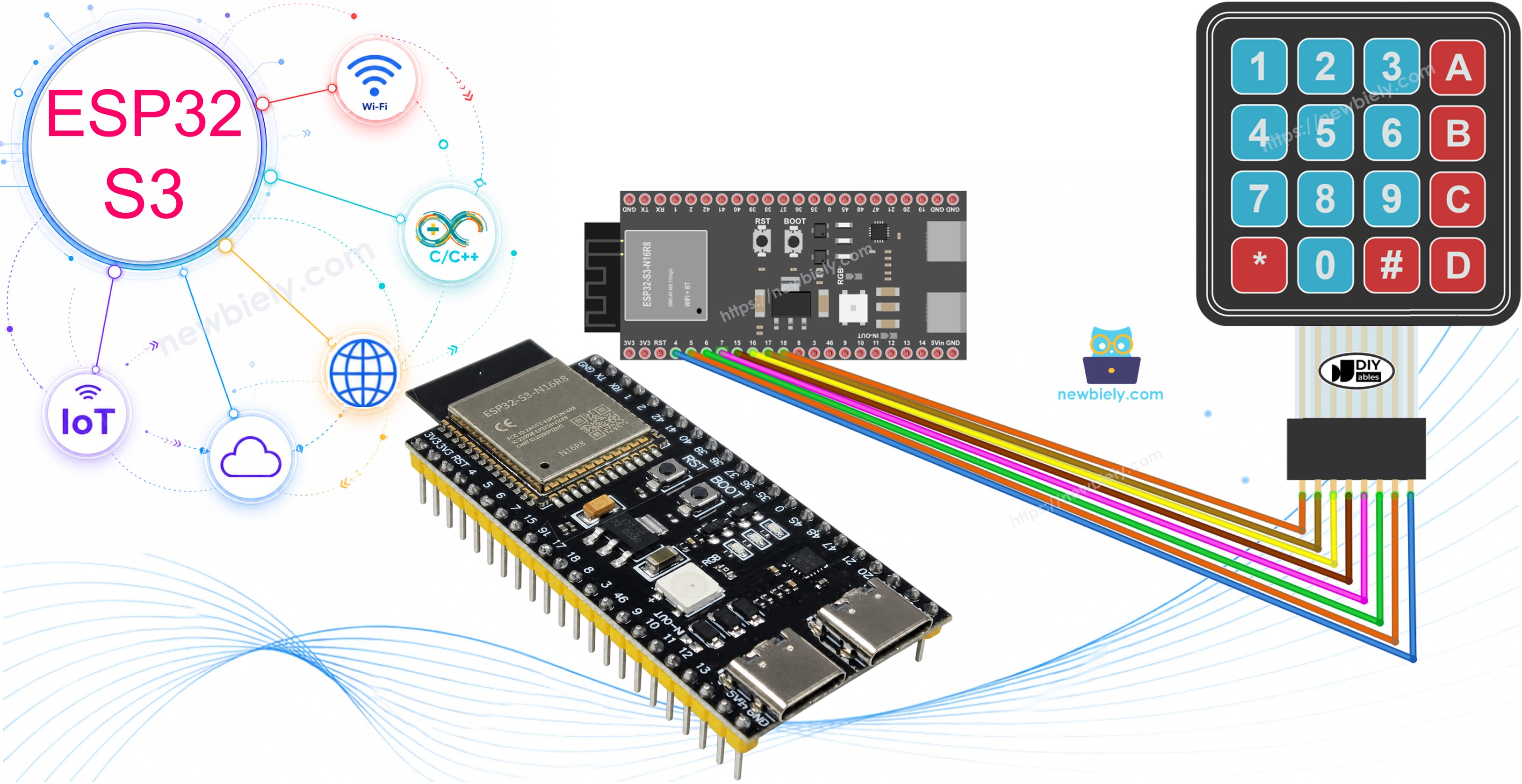
Hardware Preparation
Or you can buy the following kits:
| 1 | × | DIYables ESP32 S3 Starter Kit (ESP32 S3 included) | |
| 1 | × | DIYables Sensor Kit (18 sensors/displays) |
Additionally, some of these links are for products from our own brand, DIYables .
Overview of 4x4 Keypad
The 4x4 keypad is a membrane input device with 16 buttons arranged in a grid of four rows and four columns. Each key press is detected by scanning row and column connections in sequence, allowing the ESP32 S3 to identify exactly which button was pressed using only eight digital pins.
Key Specifications
The keypad exposes eight pins — four for rows (R1 through R4) and four for columns (C1 through C4). No power supply pin is required; the keypad relies entirely on the GPIO logic levels of the connected microcontroller. The membrane construction makes it thin and compact, and the 4x4 layout provides keys 0–9, A–D, *, and # for flexible input schemes. The keypad is fully compatible with 3.3V logic, making it a natural fit for the ESP32 S3.
Pinout
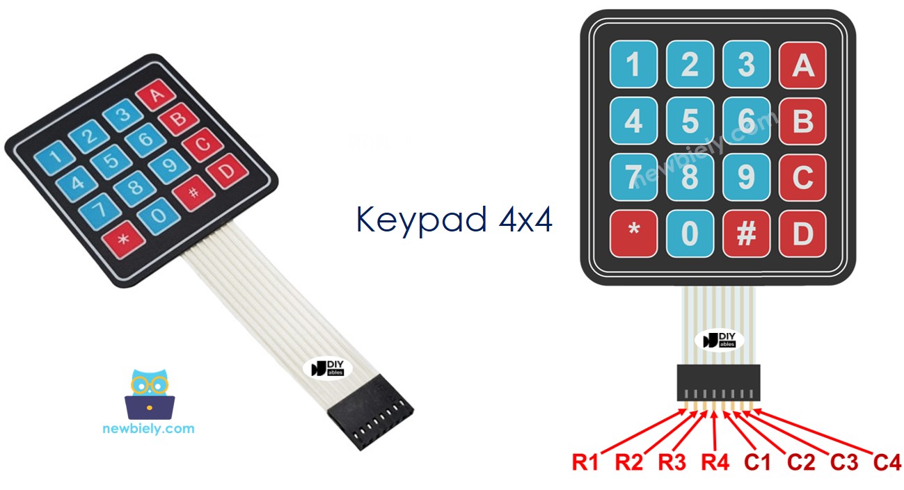
The 4x4 keypad has 8 pins organized into two groups:
- R1 pin: Row 1 — top row of keys (1, 2, 3, A)
- R2 pin: Row 2 — second row of keys (4, 5, 6, B)
- R3 pin: Row 3 — third row of keys (7, 8, 9, C)
- R4 pin: Row 4 — bottom row of keys (*, 0, #, D)
- C1 pin: Column 1 — leftmost column (1, 4, 7, *)
- C2 pin: Column 2 — second column (2, 5, 8, 0)
- C3 pin: Column 3 — third column (3, 6, 9, #)
- C4 pin: Column 4 — rightmost column (A, B, C, D)
Wiring Diagram
Connect the 4x4 keypad to the ESP32 S3 by mapping the keypad's row and column pins to available GPIO pins in order. The following table and wiring diagram show the recommended connection for this tutorial.
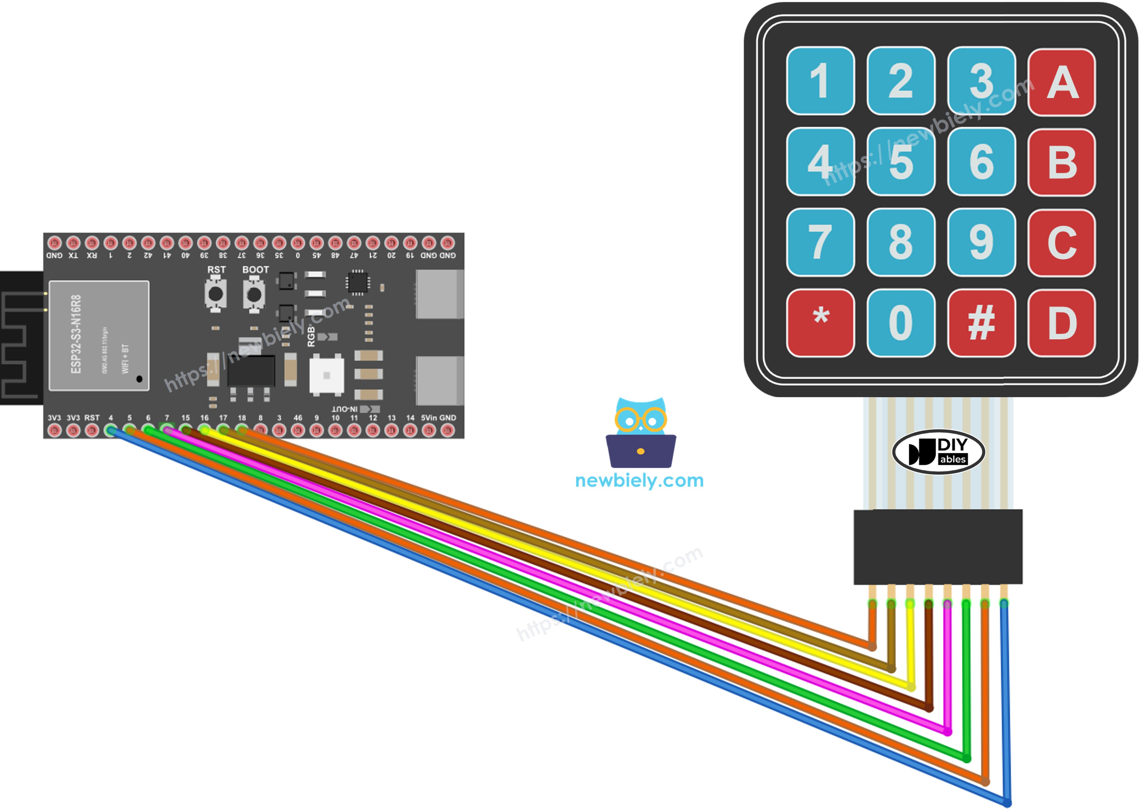
This image is created using Fritzing. Click to enlarge image
Safety Notes
The 4x4 keypad operates entirely on 3.3V logic and draws negligible current, so there is no risk of damaging the ESP32 S3 from this connection alone. Always double-check that each wire is seated firmly in its breadboard slot before uploading code — loose connections are the most common cause of missed key presses or rows and columns being swapped.
| Keypad Pin | ESP32 S3 Pin |
|---|---|
| R1 | GPIO18 |
| R2 | GPIO17 |
| R3 | GPIO16 |
| R4 | GPIO15 |
| C1 | GPIO7 |
| C2 | GPIO6 |
| C3 | GPIO5 |
| C4 | GPIO4 |
ESP32 S3 Code
The following code uses the DIYables_Keypad library to detect individual key presses on the 4x4 keypad connected to the ESP32 S3. It initializes the keypad with the row and column pin assignments, then continuously polls for key events in the main loop and prints each detected character to the Serial Monitor.
Detailed Instructions
- New to ESP32 S3? Complete our Getting Started with ESP32 S3 guide first.
- Connect the 4x4 keypad to the ESP32 S3 according to the wiring diagram above.
- Connect your ESP32 S3 to your computer using a USB Type-C cable.
- Open the Arduino IDE on your computer.
- Select your board: choose the correct ESP32 S3 board from Tools > Board menu.
- Choose your port: select the correct COM port from Tools > Port menu.
- Click the Libraries icon on the left sidebar of the Arduino IDE.
- Type DIYables_Keypad in the search box and look for the keypad library by DIYables.io.
- Click the Install button to install the keypad library.
- Search for DIYables_Keypad created by DIYables.io and click the Install button.
- Copy the code above and paste it into the Arduino IDE.
- Click the Upload button to compile and upload the sketch to the ESP32 S3.
- Open the Serial Monitor in the Arduino IDE.
- Press some keys on the keypad and observe the output.
- Pro Tip: If keys are not registering correctly, swap the row and column pin assignments in code — keypad ribbon cables can be oriented differently between manufacturers.
Serial Monitor Output
After uploading the code and opening the Serial Monitor at 115200 baud, press keys on the 4x4 keypad one at a time. The Serial Monitor will display each pressed key as a character on its own line, similar to the output below.
Keypad and Password
A common use of the keypad is for entering and verifying a password, which is the foundation of PIN-pad and door-lock projects. The password check logic relies on two special keys to control the input flow: the "*" key clears the current entry and starts fresh, while the "#" key finalises the entry and triggers a comparison against the pre-defined password stored in the sketch.
The password is built character by character from the other keys. When a key is pressed:
- If the key is not "*" or "#", add it to the password the user is entering.
- If the key is "#", compare the entered password against the pre-defined password, then clear the input.
- If the key is "*", clear the entered password without checking.
Keypad - Password Code
The following code extends the basic key reader to implement a full password-checking system on the ESP32 S3. It stores a pre-defined password in the sketch, accumulates key presses into an input string, and prints whether access is granted or denied when the user presses "#" to confirm.
Quick Steps (Password Example)
- Upload the password code to your ESP32 S3.
- Open the Serial Monitor.
- Press the keys 1234BC followed by #.
- Press the keys 1234A followed by #.
- Check the results on the Serial Monitor.
Application and Project Ideas
Once you can read keys and verify passwords with the ESP32 S3, you can adapt this foundation into many practical security and input projects.
- Door lock system: Use the password checker to control a relay or solenoid lock — unlock when the correct PIN is entered.
- Safe combination: Require a multi-step sequence of keys to open an enclosure or trigger an event.
- Alarm system PIN pad: Let users arm and disarm an alarm by entering a code on the keypad.
- Access log: Record every key press with a timestamp to an SD card for auditing who accessed a secured area.
- Calculator: Map the 0–9 keys and A–D keys to arithmetic operations to build a simple four-function calculator.
- Numeric menu navigation: Use rows and columns as directional and selection controls for an LCD menu system.
- Multi-user PIN system: Store multiple valid passwords in an array and grant access if any one of them matches.
Video Tutorial
Watch the step-by-step video walkthrough for this ESP32 S3 project below.
Challenge Yourself
Now that you can read keys and check passwords with the 4x4 keypad on the ESP32 S3, try these progressively challenging extensions to deepen your understanding.
- Beginner: Change the pre-defined password in the sketch to a six-digit code and verify it works correctly.
- Beginner: Display each key press on an I2C LCD screen instead of the Serial Monitor.
- Intermediate: Add a buzzer that beeps once for each key press and plays a longer tone when the password is accepted or rejected.
- Intermediate: Implement a lockout that disables input for 30 seconds after three consecutive incorrect password attempts.
- Advanced: Store the password in EEPROM or NVS flash so it survives power cycles, and add a key sequence to change the password at runtime.
- Advanced: Build a complete door-lock system by combining the keypad with a relay, solenoid lock, and OLED display that shows access granted or denied messages.