
ESP32 S3 - LCD 20x4
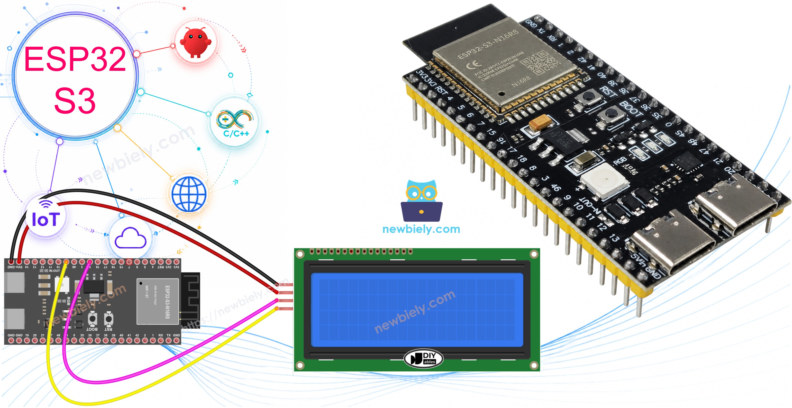
In this tutorial, we walk you through displaying text on a 20x4 LCD screen using I2C communication with the ESP32 S3 board. This beginner-friendly guide makes it easy to add a large, readable display to your ESP32 S3 projects.
What you'll build:
- A working LCD 20x4 I2C display connected to your ESP32 S3
- Text output across all four rows of the display
- Precisely positioned messages using cursor coordinates
- A foundation for sensor readouts, menus, and data dashboards
Hardware Preparation
Or you can buy the following kits:
| 1 | × | DIYables ESP32 S3 Starter Kit (ESP32 S3 included) | |
| 1 | × | DIYables Sensor Kit (18 sensors/displays) |
Additionally, some of these links are for products from our own brand, DIYables .
Buy Note: Alternatively, you can assemble the LCD I2C display using LCD 2004 Display and PCF8574 I2C Adapter Module.
Overview of LCD I2C 20x4
The LCD I2C 20x4 is a liquid crystal display module that shows 20 characters per line across 4 rows, communicating with your microcontroller over just two wires using the I2C protocol. It combines the spacious display area of a traditional parallel LCD with the simplicity of I2C, making it an excellent choice for projects that need to show multiple lines of information without consuming many GPIO pins.
Key Specifications
The LCD I2C 20x4 offers a display capacity of 20 columns by 4 rows, giving you 80 characters of total space. It communicates over I2C using only two data wires (SDA and SCL), and operates at 5V. The default I2C address is typically 0x27, though this can vary by manufacturer. A built-in LED backlight (available in blue or green) illuminates the display, and contrast is adjustable via a small onboard potentiometer. Compared to parallel LCD displays, the I2C version is far easier to wire and leaves more GPIO pins free for sensors and actuators.
Pinout
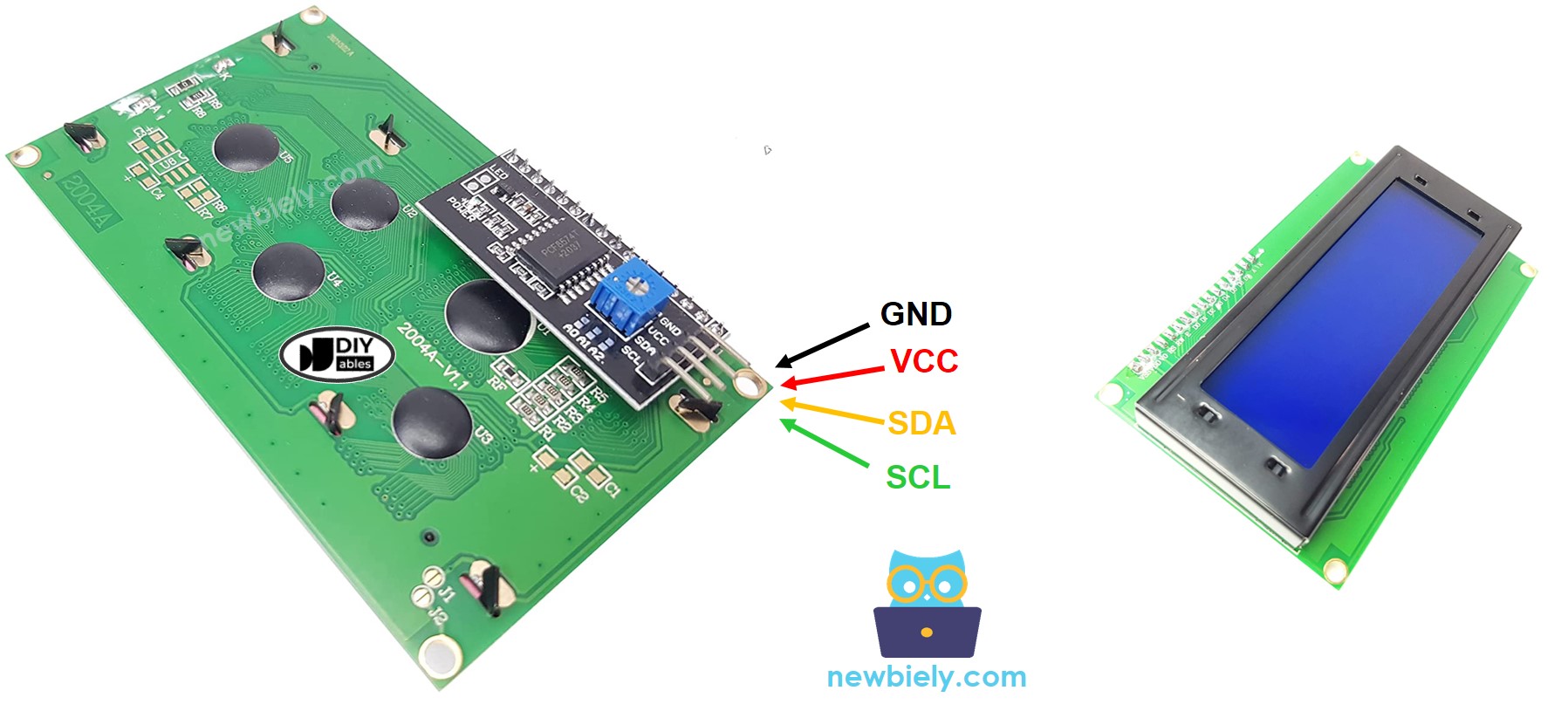
The LCD 20x4 I2C module exposes just four pins, keeping connections minimal and straightforward.
- GND: Ground pin — connect to GND (0V)
- VCC: Power supply pin — connect to 5V
- SDA: I2C data line — carries serial data between the module and the ESP32 S3
- SCL: I2C clock line — provides the serial clock signal
LCD Coordinate
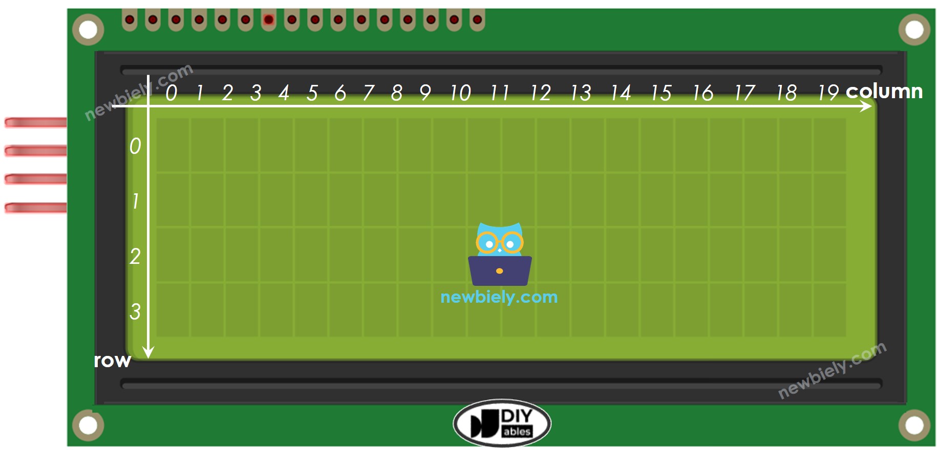
Understanding the LCD coordinate system lets you position text precisely anywhere on the screen. Columns are numbered 0 to 19 from left to right, and rows are numbered 0 to 3 from top to bottom. The top-left corner is position (0, 0) and the bottom-right corner is position (19, 3). Use setCursor(column, row) in your code to move the cursor before printing text.
Wiring Diagram
Connect the LCD 20x4 I2C display to your ESP32 S3 using the wiring table below, keeping in mind that the LCD requires 5V while the ESP32 S3 communicates at 3.3V logic (the I2C module handles the level difference). Two wiring configurations are shown depending on how you power your board.
Safety Notes
When powering the ESP32 S3 through the USB port, you can supply the LCD display from the VBUS pin, eliminating the need for an external power source. However, the VBUS pin may not deliver sufficient current for the LCD to function reliably under all conditions, so an external 5V power supply through the DC power jack is the more dependable option for permanent installations.
- USB-Powered Setup: When powering ESP32 S3 via USB port
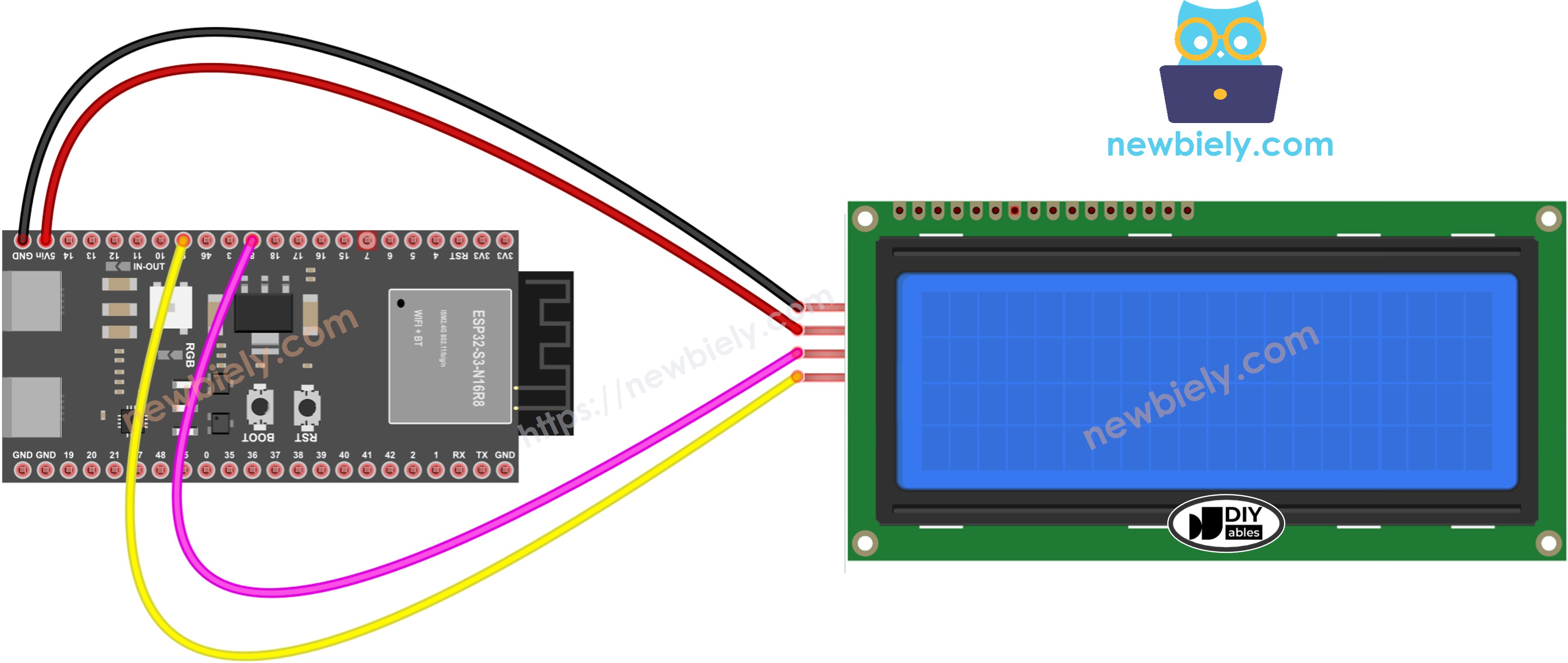
This image is created using Fritzing. Click to enlarge image
- External Power Setup: When powering ESP32 S3 via Vin pin
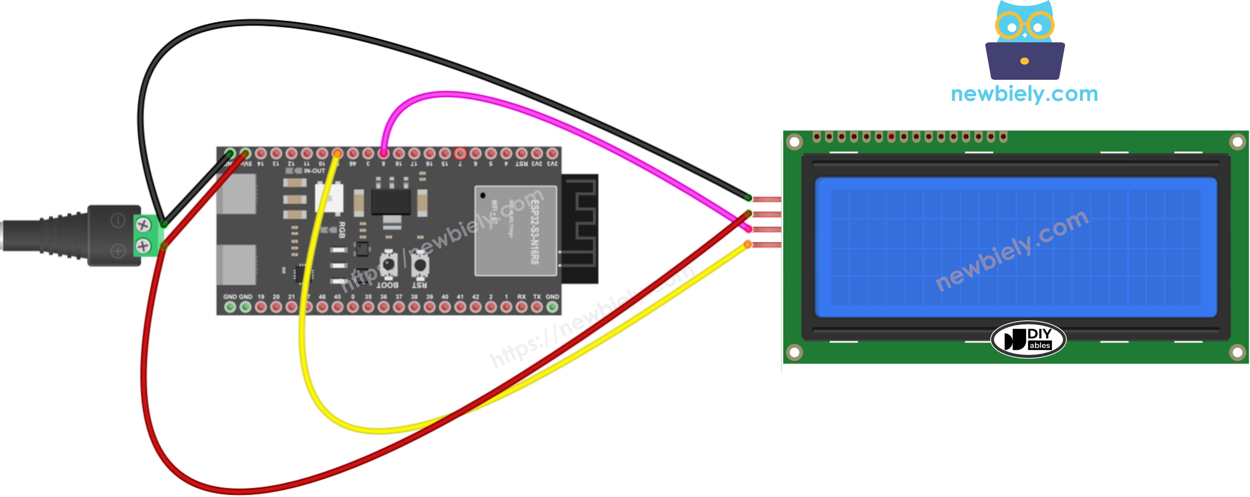
This image is created using Fritzing. Click to enlarge image
| LCD I2C | ESP32 S3 |
|---|---|
| VCC | 5V |
| GND | GND |
| SDA | GPIO8 |
| SCL | GPIO9 |
How To Program For LCD I2C
The DIYables_LCD_I2C library abstracts the low-level I2C communication details so you can focus on placing text on screen rather than managing the display protocol. The library initializes the hardware, controls the backlight, and provides intuitive methods for cursor positioning and text printing that work seamlessly with the ESP32 S3.
The following code initializes the LCD at I2C address 0x27 with 20 columns and 4 rows, turns on the backlight, then uses setCursor() to position text on each of the four rows before calling lcd.print() to display the message. No repeated updates are needed in the loop since the content is static.
Include the Library
Declare LCD Object
Initialize the LCD
Set Cursor Position
Print Text Message
※ NOTE THAT:
The I2C address of LCD can vary according to the manufacturers. In the code, we used 0x27 that is specified by DIYables manufacturer
ESP32 S3 Code
Detailed Instructions
- New to ESP32 S3? Complete our Getting Started with ESP32 S3 guide first.
- Connect the hardware: Wire the LCD 20x4 I2C to your ESP32 S3 following the wiring diagram above.
- Plug in USB cable: Connect the ESP32 S3 to your computer using a USB Type-C cable.
- Open Arduino IDE: Launch the Arduino IDE software on your computer.
- Select your board: Choose ESP32 S3 and the correct COM port from the Arduino IDE.
- Install the library: Click the Library Manager icon on the left sidebar of Arduino IDE.
- Search for library: Type "DIYables LCD I2C" in the search box.
- Install DIYables library: Find the DIYables_LCD_I2C library by DIYables and click Install.
- Search for DIYables LCD I2C created by DIYables.io and click the Install button.
- Copy the code: Paste the example code above into Arduino IDE.
- Upload the code: Click the Upload button to transfer code to your ESP32 S3.
- View the display: Check the LCD screen — you should see text on all four rows.
- Experiment: Try changing the text content and cursor positions to customize the display.
- Pro Tip: If nothing appears on the LCD, adjust the small potentiometer on the back of the I2C module to increase contrast until the text becomes visible.
Application Ideas
The ESP32 S3 paired with an LCD 20x4 I2C display is a versatile combination well-suited to projects that need to present multiple lines of live or static information at a glance.
- Weather station: Display temperature, humidity, pressure, and forecast on four dedicated rows.
- Smart thermostat: Show current temperature, target temperature, mode, and schedule simultaneously.
- Multi-sensor data logger: Present readings from several sensors on screen at the same time.
- Home automation controller: Build a menu-driven interface for toggling and configuring devices.
- Real-time clock: Show date, time, day of week, and alarm status across the four rows.
- Audio player interface: Display song title, artist, album, and playback progress.
- Network monitor: Show IP address, connection status, signal strength, and data usage in real time.
Video Tutorial
Watch the step-by-step video walkthrough for this ESP32 S3 project below.
...VIDEO Z5z8MnJXb_s
Challenge Yourself
These progressive challenges will help you build on what you have learned and push your ESP32 S3 LCD skills further.
- Beginner: Display your name on the first row and your favorite quote spread across rows 2 through 4.
- Beginner: Create a countdown timer that updates the seconds remaining on the LCD each second.
- Intermediate: Read temperature from a DHT11 sensor and display the value with a custom degree symbol on the LCD.
- Intermediate: Build a scrolling text marquee that smoothly moves a long message across the screen.
- Advanced: Create a multi-screen menu system that cycles through different information panels every 5 seconds.
- Advanced: Design a real-time system monitor showing WiFi status, uptime, memory usage, and live sensor data across all four rows.