
ESP32 S3 - Electromagnetic Lock
Learning to control an electromagnetic lock with ESP32 S3 is a great introduction to smart door systems and home security projects. This tutorial shows you how to wire and program a maglock using a relay module.
What you'll build:
- A circuit connecting an electromagnetic lock to the ESP32 S3 via a relay module
- Code that locks and unlocks the door automatically every 5 seconds
- Serial Monitor output showing real-time lock status
- A foundation for building button- or RFID-based access control systems
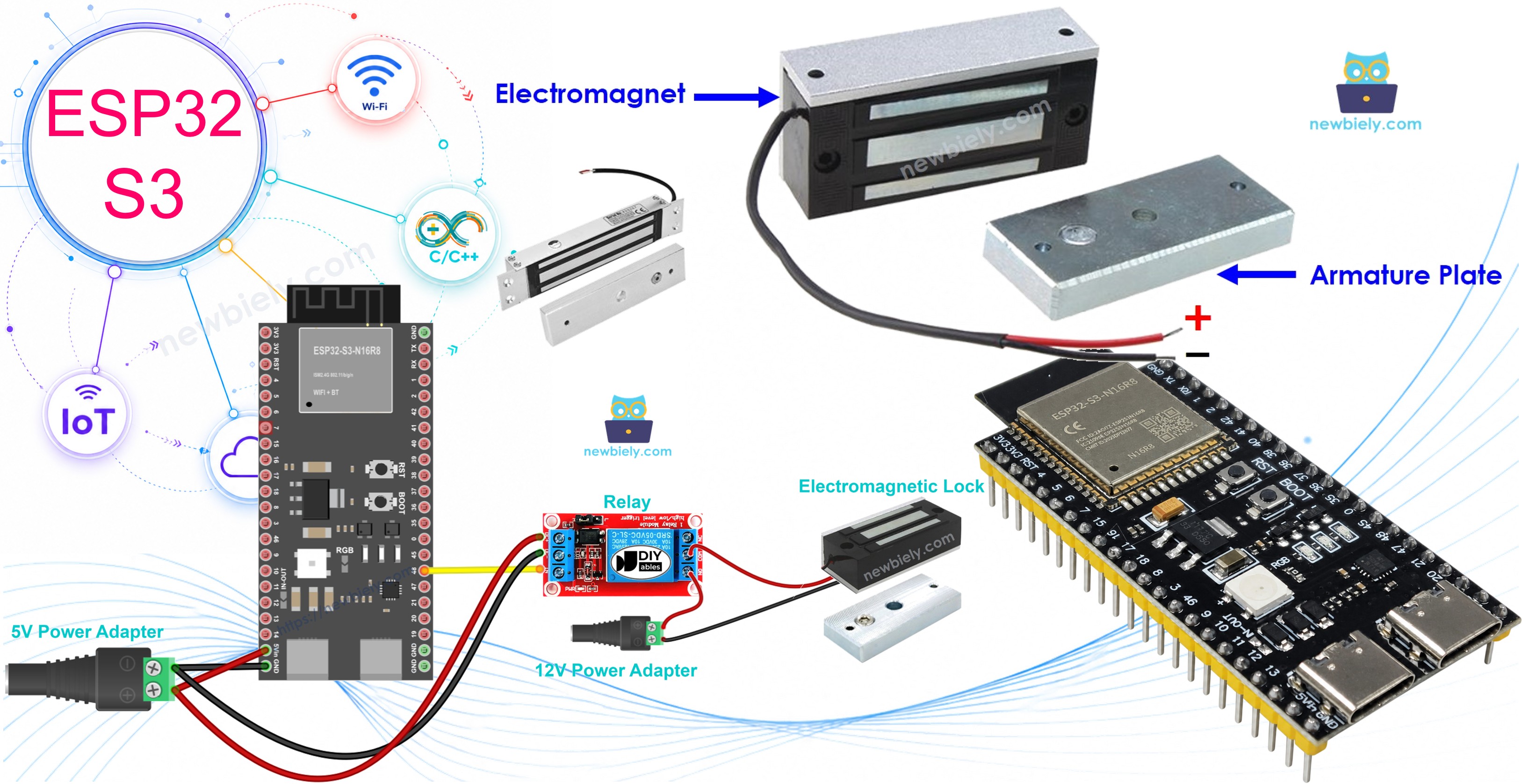
Hardware Preparation
Or you can buy the following kits:
| 1 | × | DIYables ESP32 S3 Starter Kit (ESP32 S3 included) | |
| 1 | × | DIYables Sensor Kit (18 sensors/displays) |
Additionally, some of these links are for products from our own brand, DIYables .
Overview of Electromagnetic Lock
An electromagnetic lock (also called a maglock) is a locking device that uses an electromagnet to hold a door securely closed. It consists of two parts — an electromagnet mounted on the door frame and a steel armature plate attached to the door itself — that are held together by magnetic force whenever power is applied. Because there are no mechanical parts, maglocks are durable, fast-acting, and commonly found in commercial access control systems.
Key Specifications
Electromagnetic locks typically operate at 12V, 24V, or 48V DC and can produce a holding force between 280 kg and 600 kg depending on the model. They follow a fail-safe design: when power is removed the magnetic field collapses and the door releases, which is an important safety feature in emergency-exit scenarios. The lock is controlled through a simple two-wire connection to its power supply, making it easy to integrate with a relay module driven by the ESP32 S3.
Electromagnetic Lock Components
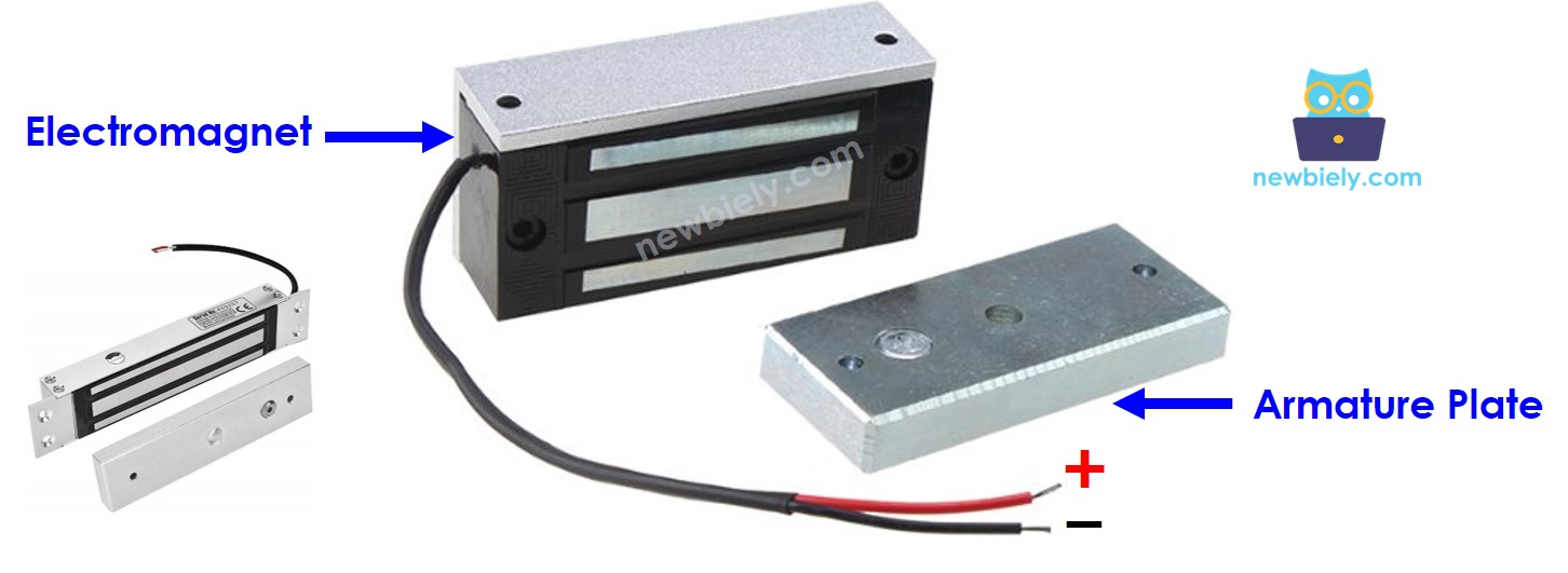
The electromagnetic lock is composed of two components:
- Armature plate: Attached on the moving part of the door (the door itself)
- Electromagnet: Attached on the door frame with two wires connected to the power source
When the door is closed, the two components are in contact with each other.
How Electromagnetic Lock Works
- Powered (Locked): When the electromagnet receives power ⇒ it creates a strong magnetic field ⇒ attracts the armature plate ⇒ door is locked
- Unpowered (Unlocked): When power is cut ⇒ no magnetic field ⇒ armature plate releases ⇒ door is unlocked
Because the ESP32 S3 outputs only 3.3V at low current, it cannot drive a high-voltage electromagnetic lock directly. A relay module bridges the two systems: the ESP32 S3 controls the relay's low-voltage coil, and the relay switches the lock's 12V circuit on and off. See the ESP32 S3 - Relay tutorial for relay basics.
Control Logic with Relay (Normally Open Mode):
- ESP32 pin LOW ⇒ relay open ⇒ electromagnet unpowered ⇒ door unlocked
- ESP32 pin HIGH ⇒ relay closed ⇒ electromagnet powered ⇒ door locked
Wiring Diagram between Electromagnetic Lock and ESP32 S3
Connect the electromagnetic lock to your ESP32 S3 using a relay module as the high-voltage switch. The relay isolates the 12V lock circuit from the ESP32 S3's 3.3V logic, protecting the board from damage.
Safety Notes
Always disconnect power from both the ESP32 S3 and the 12V supply before making any wiring changes. Verify that the relay module's contact rating (voltage and current) matches or exceeds the electromagnetic lock's requirements, and never connect the EM lock's high-voltage wires directly to any ESP32 S3 pin.
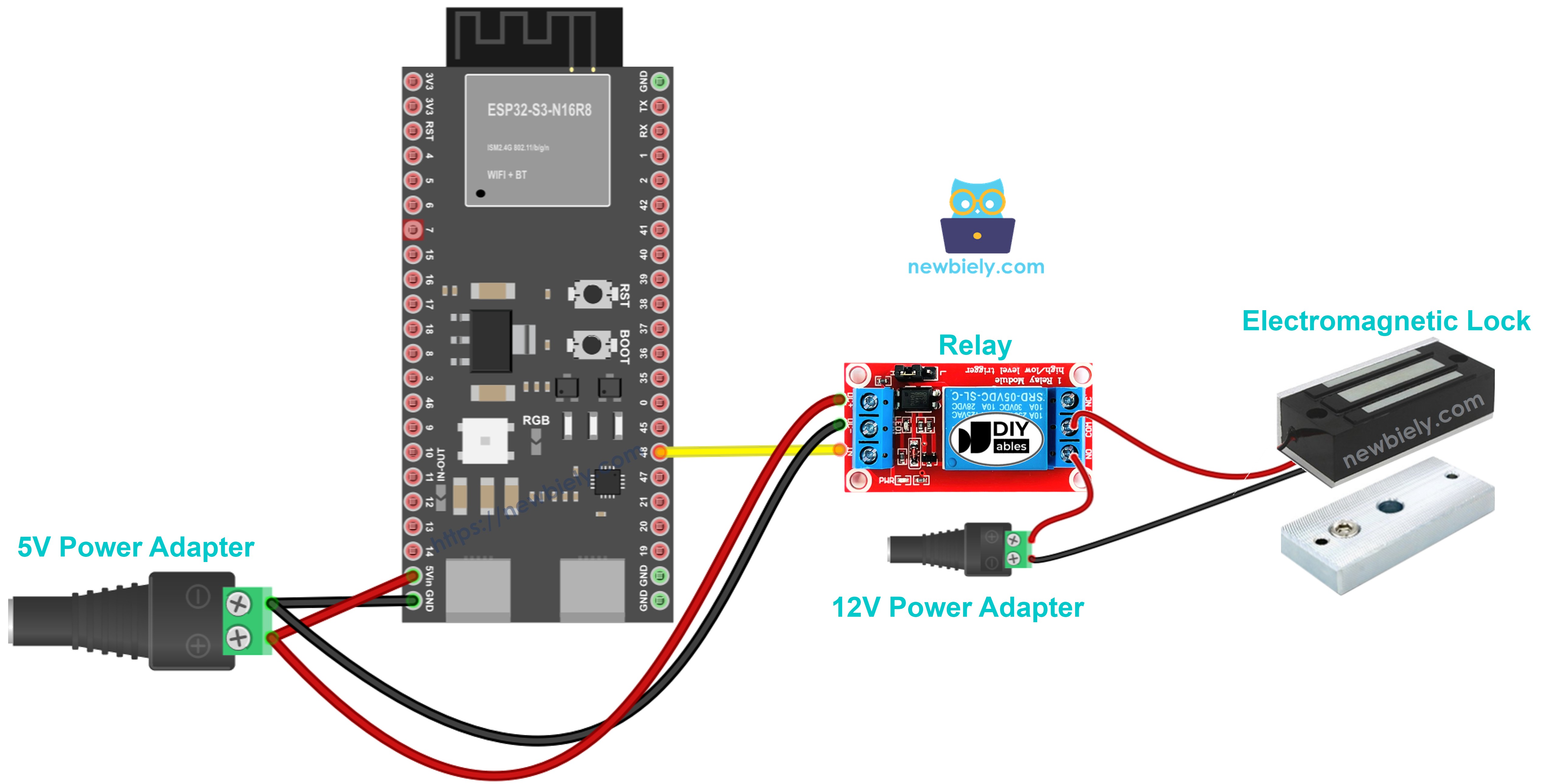
This image is created using Fritzing. Click to enlarge image
| Component Pin | ESP32 S3 Pin | Notes |
|---|---|---|
| Relay Signal (IN) | D7 | Controls relay on/off |
| Relay VCC | 5V | Powers the relay module |
| Relay GND | GND | Common ground |
| Relay COM | 12V Power + | From power adapter |
| Relay NO | EM Lock Wire 1 | Normally open connection |
| EM Lock Wire 2 | 12V Power - | Completes the circuit |
ESP32 S3 Code
The following code demonstrates basic electromagnetic lock control by alternating between locked and unlocked states every 5 seconds. It configures pin D7 as an output, drives it HIGH to engage the relay and lock the door, then pulls it LOW to release the relay and unlock the door, repeating the cycle indefinitely while printing the current status to the Serial Monitor.
Detailed Instructions
- New to ESP32 S3? Complete our Getting Started with ESP32 S3 guide first.
- Setup Arduino IDE: If this is the first time you use ESP32 S3, see how to setup the environment for ESP32 S3 on Arduino IDE.
- Upload the Code: Copy the above code and paste it into Arduino IDE.
- Compile and Upload: Click the Upload button on Arduino IDE to compile and upload the code to your ESP32 S3 board.
- Test the Lock: Place the armature plate close to the electromagnet.
- Observe the Action: Watch the attraction between the armature plate and the electromagnet change every 5 seconds.
- Open Serial Monitor: Set baud rate to 115200 to see live lock status messages.
- Pro Tip: Mark the armature plate position on your door frame for easy alignment during final installation.
Serial Monitor Output
Open the Serial Monitor at 115200 baud after uploading and you will see output similar to the following:
Real-World Applications
Electromagnetic locks controlled by the ESP32 S3 suit a wide range of security and automation projects, from simple prototypes to production-ready access systems.
- Smart Home Entry: Build keypad or RFID-based door access systems.
- Office Access Control: Create employee badge readers with event logging.
- Lab or Tutorial Security: Restrict access to sensitive areas using authentication.
- Automated Gates: Control gate locks with remote triggers or sensor inputs.
- Cabinet Security: Lock storage units or display cases electronically.
- IoT Security Systems: Integrate with WiFi for remote lock/unlock via a smartphone app.
Video Tutorial
Watch the step-by-step video walkthrough for this ESP32 S3 project below.
...VIDEO https://www.youtube.com/embed/5yvlkAOr9C4
...VIDEO
Challenge Yourself
The examples above cover the basics; these challenges will push your ESP32 S3 project further and help you build real access control skills.
- Beginner: Add an LED indicator that lights up whenever the door is locked.
- Beginner: Modify the timing so the door stays unlocked for 10 seconds instead of 5.
- Intermediate: Add a pushbutton that manually unlocks the door on demand.
- Intermediate: Implement a simple PIN code system using multiple buttons.
- Advanced: Create a web server to control the lock remotely over WiFi.
- Advanced: Add RFID authentication for keyless entry with support for multiple user cards.