
ESP32 S3 - Solenoid Lock
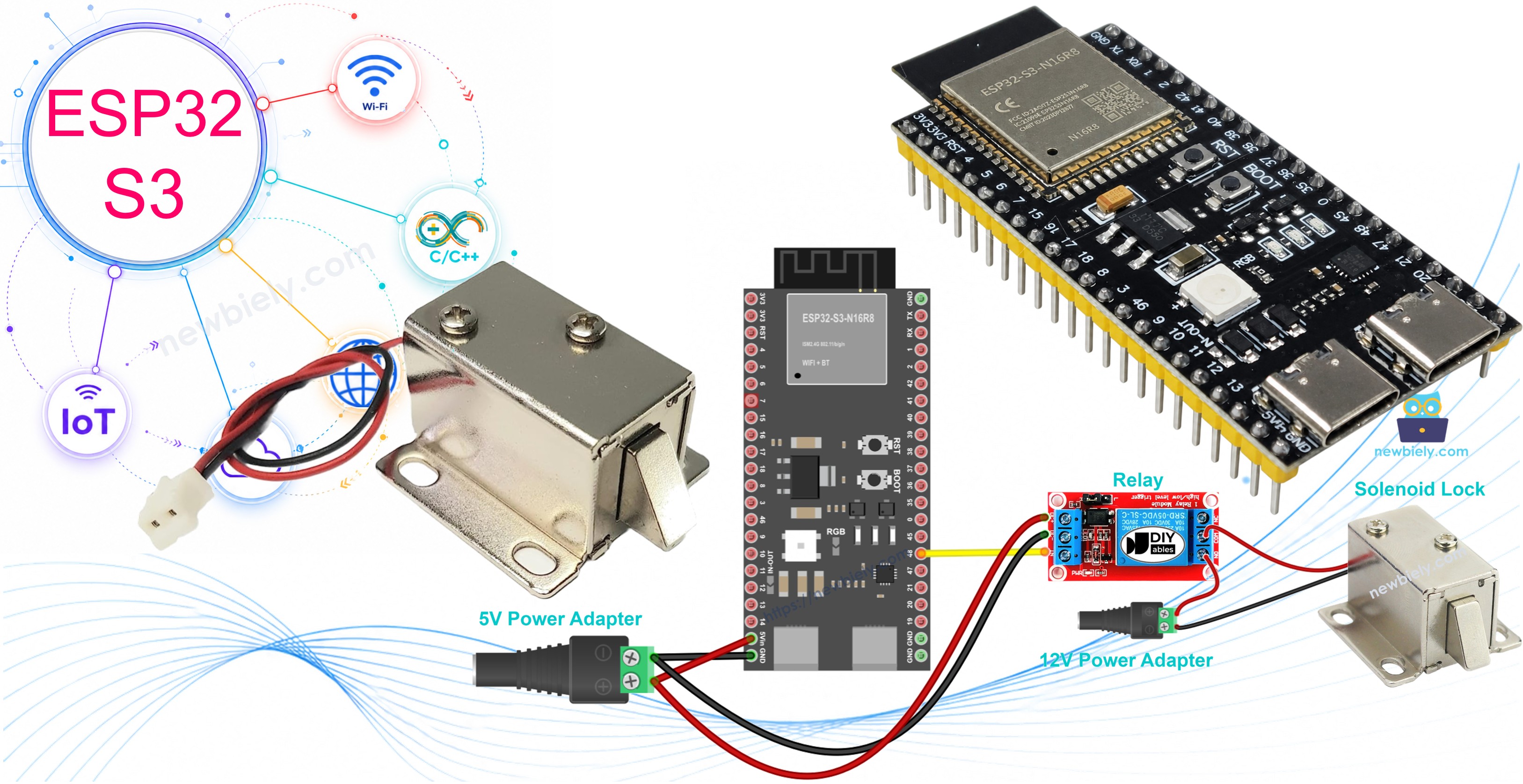
Solenoid locks (also known as electric strike locks) are a popular choice for DIY electronic access control, and the ESP32 S3 makes an excellent controller for these devices. This tutorial walks you through everything you need to wire, program, and operate a solenoid lock with your ESP32 S3 board.
What you'll build:
- A working solenoid lock circuit connected to the ESP32 S3 through a relay module
- Firmware that automatically locks and unlocks the door on a timed cycle
- Clear Serial Monitor feedback showing the current lock state
- A foundation you can extend with buttons, RFID, or WiFi control
Alternative option: Need a different lock type? Check out our ESP32 S3 - Electromagnetic Lock tutorial for another approach to electronic access control.
Hardware Preparation
Or you can buy the following kits:
| 1 | × | DIYables ESP32 S3 Starter Kit (ESP32 S3 included) | |
| 1 | × | DIYables Sensor Kit (18 sensors/displays) |
Additionally, some of these links are for products from our own brand, DIYables .
Overview of Solenoid Lock
A solenoid lock (also called an electric strike lock) is an electromagnetic locking device that uses electrical current to control a mechanical bolt or strike plate. When power is applied, an internal coil generates a magnetic field that pulls or extends the strike into its locked position; when power is removed, a spring returns the strike to the unlocked position. This simple two-state behavior makes solenoid locks straightforward to integrate with microcontrollers like the ESP32 S3.
Key Specifications
Most solenoid locks operate on 12V DC, though 24V and 48V variants exist. The lock has only two connection wires — a positive (red) wire and a negative (black) wire — making wiring uncomplicated. The device locks when powered and unlocks when unpowered, and its response is essentially instantaneous, which suits both automated timing and real-time button-triggered applications.
Pinout
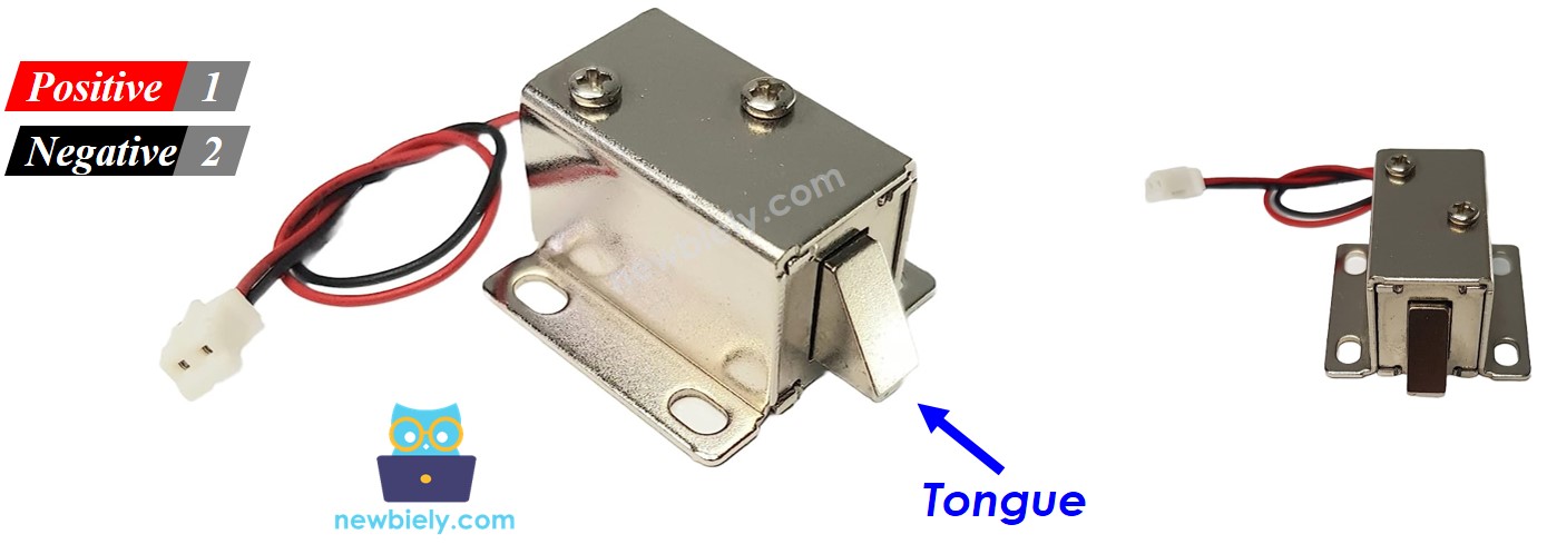
The solenoid lock exposes two wires for connection:
- Positive (+) wire (red): Connect to the 12V rail of your DC power supply (routed through the relay)
- Negative (-) wire (black): Connect directly to the GND of your DC power supply
How It Works
When the solenoid lock receives power, the lock tongue (strike) extends outward and the door is locked. When power is removed, the spring mechanism retracts the strike and the door is unlocked.
The relay acts as a switchable gate between the high-voltage power supply and the solenoid lock. In Normally Open mode, the relay is open by default (lock unpowered, door unlocked); when the ESP32 S3 drives the relay signal HIGH, the relay closes, powering the lock and securing the door.
※ NOTE THAT:
Important: The solenoid lock requires 12V, 24V, or 48V power supply. You CANNOT connect it directly to ESP32 S3 pins (which only output 3.3V). You MUST use a relay as an intermediary to control the high-voltage power to the lock.
By connecting the ESP32 S3 to the relay, you can program automated or button-triggered lock control. Learn more about relay basics in our ESP32 S3 - Relay tutorial.
Wiring Diagram
Connect your solenoid lock to the ESP32 S3 through a relay module, keeping the high-voltage solenoid circuit isolated from the low-voltage ESP32 S3 circuit. Both circuits must share a common GND for reliable signal control.
Safety Notes
Always double-check all connections before applying power to the circuit. Ensure that your 12V power supply matches the voltage rating printed on your solenoid lock, and keep high-voltage wiring physically separated from the ESP32 S3 GPIO traces to avoid noise or damage.
| Component Pin | ESP32 S3 Pin | Notes |
|---|---|---|
| Relay Signal | D7 | Control signal from ESP32 |
| Relay VCC | 5V | Power for relay module |
| Relay GND | GND | Ground connection |
| Solenoid Lock (+) | 12V Power Supply (+) | Via relay COM and NO |
| Solenoid Lock (-) | 12V Power Supply (-) | Direct to power supply GND |
| 12V Power GND | ESP32 GND | Common ground required |
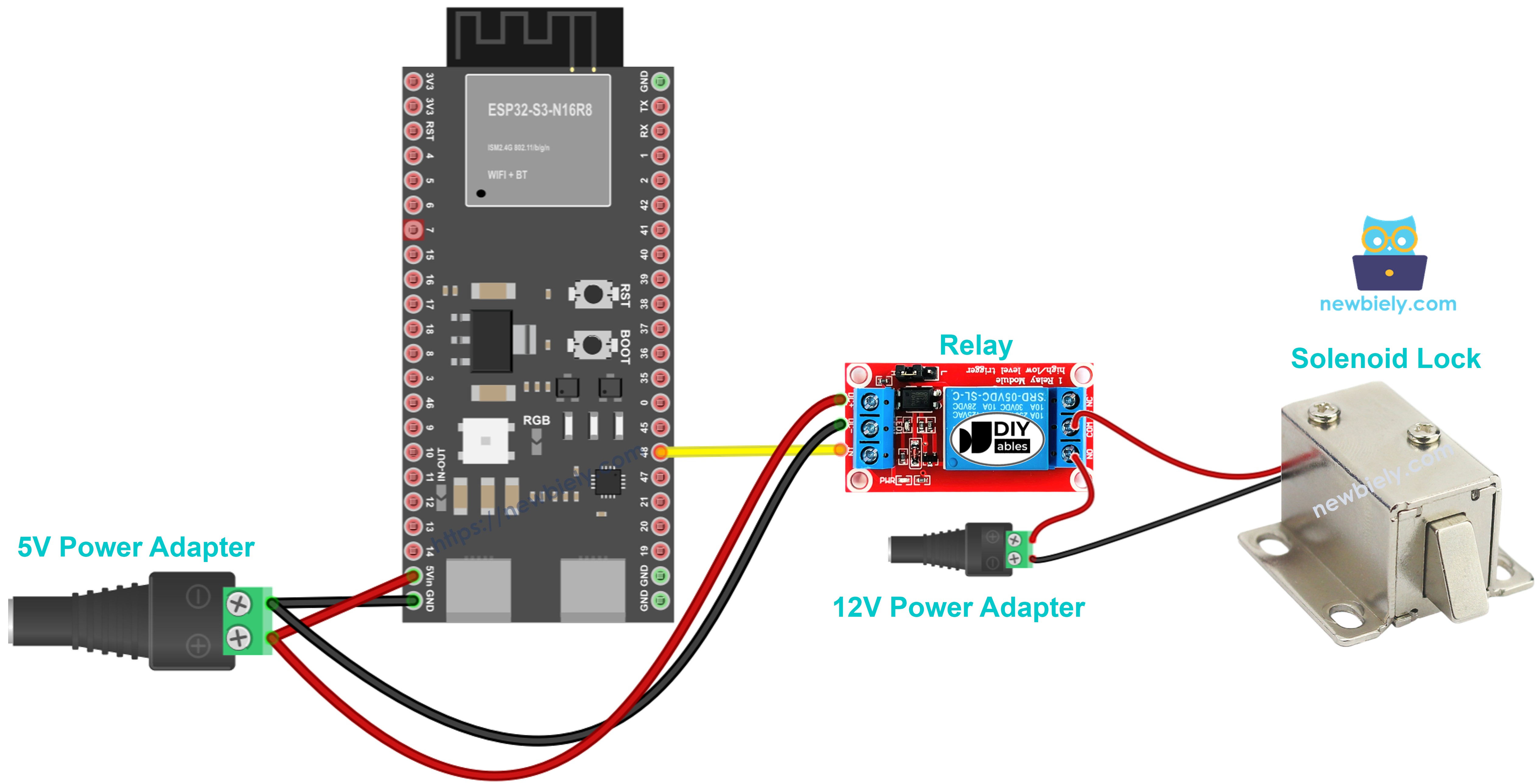
This image is created using Fritzing. Click to enlarge image
ESP32 S3 Code
The following code automatically locks and unlocks the door every five seconds, giving you a clear demonstration of the solenoid lock mechanism before you adapt it to your own trigger logic. It defines pin D7 as the relay control output, drives that pin HIGH to close the relay (locking the door), waits five seconds, then drives it LOW to open the relay (unlocking the door), and repeats indefinitely. Serial Monitor messages accompany every state change so you can confirm correct operation without physically watching the lock.
Code Explanation
The sketch is intentionally minimal so that the core relay-driving logic is easy to follow and extend. #define RELAY_PIN 7 maps pin D7 to the relay signal wire. Inside setup(), pinMode(RELAY_PIN, OUTPUT) configures that pin as a digital output. In loop(), digitalWrite(RELAY_PIN, HIGH) closes the relay and powers the solenoid lock (locked state), while digitalWrite(RELAY_PIN, LOW) opens the relay and cuts power to the lock (unlocked state). Each state persists for 5 000 ms via delay(5000) before the next transition.
Detailed Instructions
- New to ESP32 S3? Complete our Getting Started with ESP32 S3 guide first.
- Wire the components: Follow the wiring diagram above carefully, ensuring proper relay and power connections.
- Connect ESP32 S3: Plug your ESP32 S3 into your computer using the USB Type-C cable.
- Open Arduino IDE: Launch the Arduino IDE on your computer.
- Select board and port: Choose ESP32 S3 and its corresponding COM port.
- Copy the code: Copy the solenoid lock code provided above.
- Upload code: Paste into Arduino IDE and click the Upload button.
- Observe operation: Watch the lock tongue extend and retract every 5 seconds.
- Pro Tip: Start with longer intervals (10–15 seconds) to clearly observe the lock mechanism and verify proper operation before adjusting the timing for your specific application.
Serial Monitor Output
Open the Serial Monitor at 115200 baud to watch the lock cycle in real time. You should see output similar to the following:
Project Ideas
The ESP32 S3 solenoid lock combination opens the door (literally) to a wide range of practical access control and automation projects.
- Smart cabinet lock: Secure storage with remote unlock via WiFi or Bluetooth.
- Password-protected door: Use keypad input to control entry access.
- RFID access control: Unlock with authorized RFID cards or tags.
- Time-based security: Automatically lock and unlock at scheduled times.
- Motion-activated lock: Lock doors automatically when motion is detected nearby.
- IoT smart locker: Control multiple locks through a web interface hosted on the ESP32 S3.
- Pet door with timer: Allow pet access only during specific hours of the day.
Video Tutorial
Watch the step-by-step video walkthrough for this ESP32 S3 project below.
Challenge Yourself
The timed lock-unlock sketch is a solid starting point, but there is plenty of room to expand the project into something more sophisticated.
- Beginner: Modify the code to keep the door locked for 10 seconds and unlocked for 2 seconds.
- Beginner: Add an LED indicator that shows lock status (red = locked, green = unlocked).
- Intermediate: Create a toggle system where pressing a button locks or unlocks the door alternately.
- Intermediate: Add a buzzer that beeps once when locking and twice when unlocking.
- Advanced: Build a keypad-based security system with password verification before unlocking.
- Advanced: Create a WiFi-enabled lock system controllable from your smartphone app using the ESP32 S3's built-in wireless capabilities.