
ESP32 S3 - LDR Module
The LDR light sensor module is a simple yet powerful component for detecting and measuring light levels with your ESP32 S3. This beginner-friendly tutorial walks you through connecting and programming the LDR module to sense ambient light in real-world projects.
In this tutorial, we will learn how to use an ESP32 S3 and an LDR light sensor module together to detect and measure the amount of light. What you'll build:
- Understand what an LDR light sensor module is and how it works
- Wire the LDR light sensor module to your ESP32 S3
- Program the ESP32 S3 to detect light using the digital output (DO) pin
- Program the ESP32 S3 to measure light levels using the analog output (AO) pin
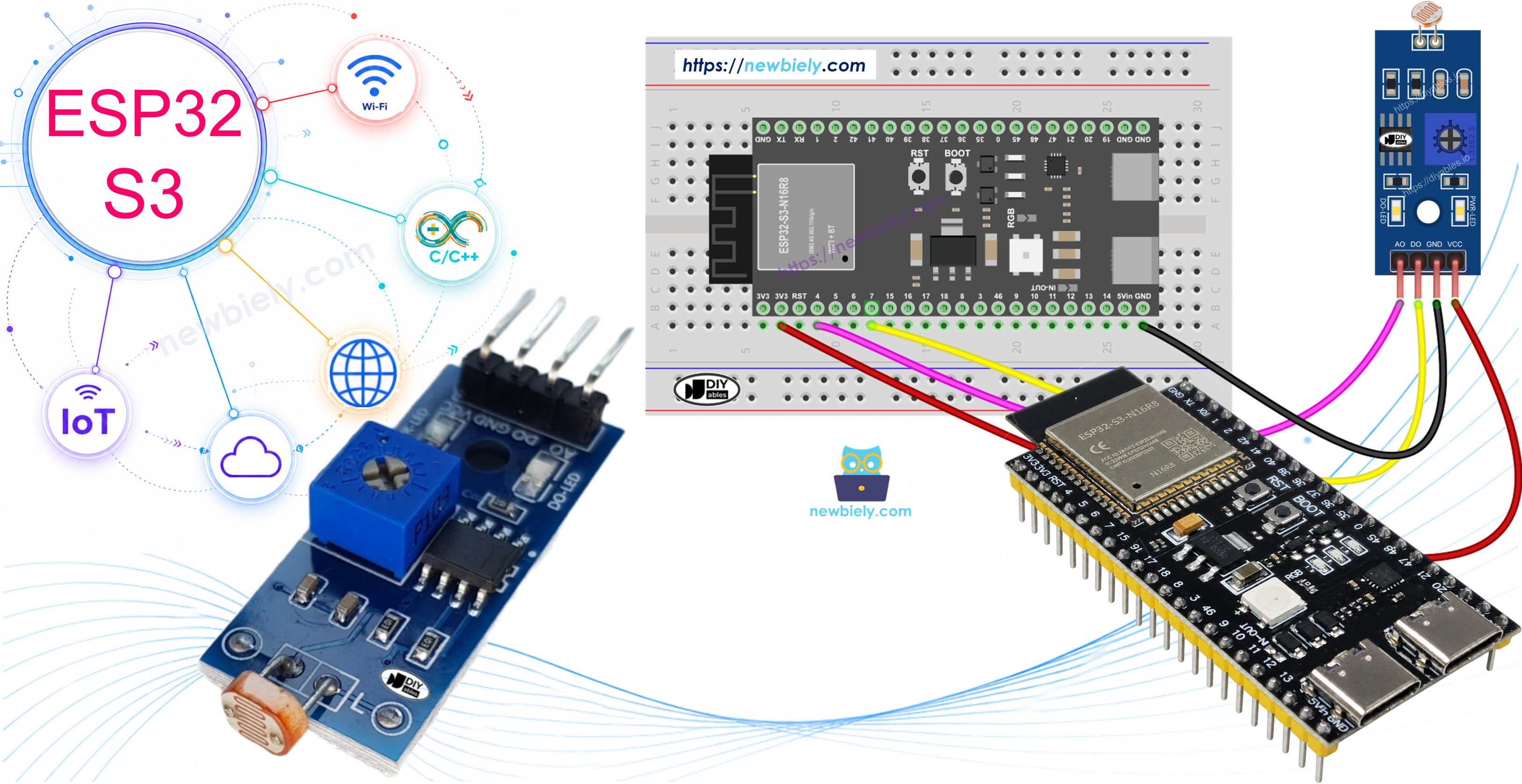
Afterward, you can change the code to make an LED or a light bulb turn on (using a relay) when it senses light.
If you're interested in a light sensor in its raw form, I suggest exploring the tutorial for the ESP32 S3 - Light Sensor.
Hardware Preparation
Or you can buy the following kits:
| 1 | × | DIYables ESP32 S3 Starter Kit (ESP32 S3 included) | |
| 1 | × | DIYables Sensor Kit (18 sensors/displays) |
Additionally, some of these links are for products from our own brand, DIYables .
Overview of LDR Light Sensor Module
The LDR light sensor module is a digital and analog sensor that detects and measures ambient light intensity in your environment. It combines a light-dependent resistor with onboard signal conditioning circuitry, making it straightforward to use with the ESP32 S3 without any additional components. The built-in potentiometer lets you fine-tune the detection threshold to suit your specific lighting conditions.
Key Specifications
The module operates on a supply voltage between 3.3V and 5V, which makes it directly compatible with the ESP32 S3's 3.3V GPIO logic. It provides two output types — a digital output (DO) and an analog output (AO) — so you can choose threshold-based detection or continuous light level measurement depending on your project. A power LED and a status LED are included on the board for at-a-glance monitoring, and the compact form factor fits easily on a standard breadboard.
Pinout
The LDR light sensor module exposes four pins for connecting to your ESP32 S3:
- VCC: Power supply pin — connect to 3.3V on the ESP32 S3
- GND: Ground pin — connect to GND on the ESP32 S3
- DO: Digital output pin — outputs HIGH when dark, LOW when bright (threshold adjustable via the onboard potentiometer)
- AO: Analog output pin — outputs a variable voltage proportional to light intensity (lower value = brighter light)
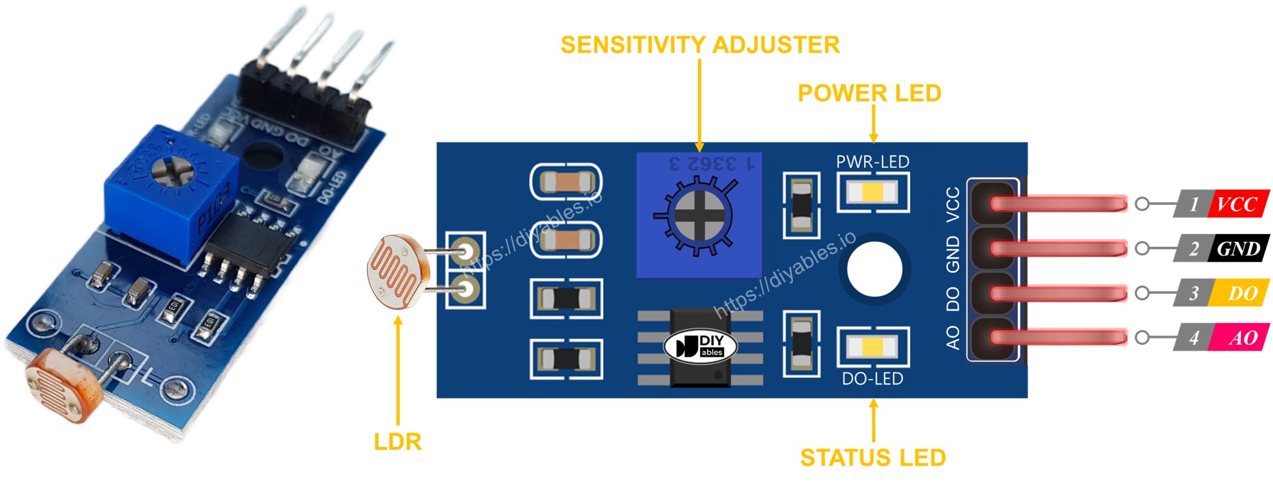
Additionally, the LDR light sensor module is equipped with two LED indicators:
- The PWR-LED indicator shows the power status.
- The DO-LED indicator reflects the state of light on the DO pin: it illuminates when there is light and remains off when it is dark.
How It Works
Regarding the DO pin:
- The LDR light sensor module has a potentiometer that allows you to adjust the sensitivity or threshold for detecting light.
- When the light intensity in the surrounding environment is above the set threshold (considered as light), the output of the sensor on the DO pin becomes LOW, and the DO-LED turns on.
- When the light intensity in the surrounding environment is below the set threshold (considered as dark), the output of the sensor on the DO pin becomes HIGH, and the DO-LED turns off.
Regarding the AO pin:
- The value read from the AO pin is inversely proportional to the light intensity in the surrounding environment. In other words, as the light intensity increases (brighter), the value on the AO pin decreases.
- Similarly, as the light intensity decreases (darker), the value on the AO pin increases.
It's important to note that adjusting the potentiometer does not affect the value on the AO pin.
Wiring Diagram
Connect the LDR light sensor module to your ESP32 S3 by matching each module pin to the corresponding ESP32 S3 pin as shown in the diagram below. You can use the digital output (DO), the analog output (AO), or both simultaneously depending on your project requirements.
Safety Notes
Always connect the VCC pin to the 3.3V rail on the ESP32 S3 rather than the 5V rail to stay within the board's GPIO voltage tolerance. Double-check that GND is shared between the module and the board before powering on, as a floating ground will produce erratic readings.
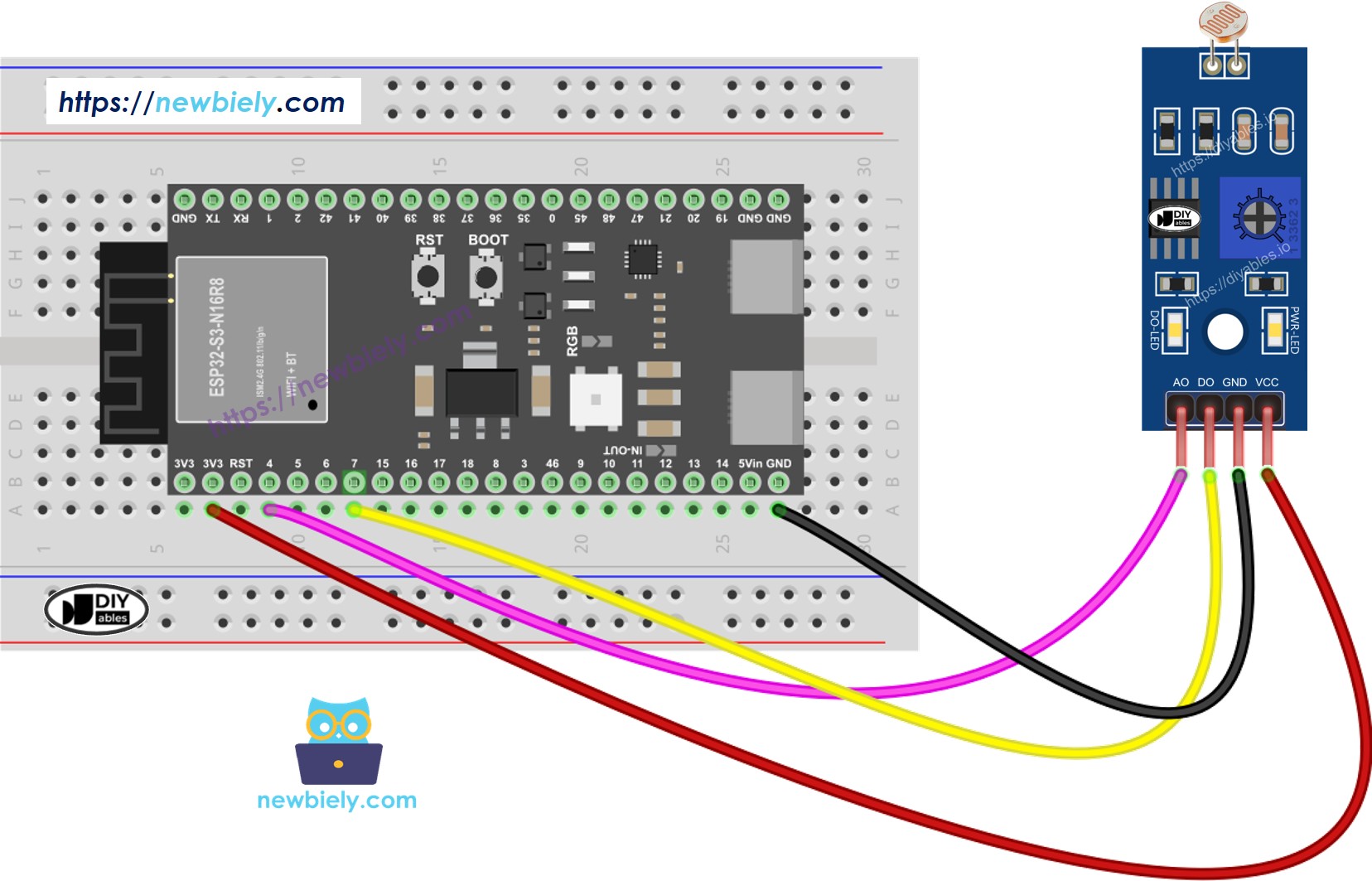
This image is created using Fritzing. Click to enlarge image
| LDR Module Pin | ESP32 S3 Pin |
|---|---|
| VCC | 3.3V |
| GND | GND |
| DO | GPIO7 |
| AO | GPIO8 (GPIO8 / ADC1_CH7) |
ESP32 S3 Code - Read value from DO pin
The following code demonstrates how to read the digital output from the LDR light sensor module using the ESP32 S3. It configures a GPIO pin as a digital input, reads the HIGH or LOW signal produced by the sensor, and prints the current light status to the Serial Monitor. The detection threshold is set by turning the onboard potentiometer on the module itself.
Detailed Instructions
- New to ESP32 S3? Complete our Getting Started with ESP32 S3 guide first.
- Wire the components: Connect the LDR light sensor module to the ESP32 S3 according to the wiring diagram shown above.
- Connect ESP32 S3: Plug the ESP32 S3 into your computer using a USB Type-C cable.
- Select board: Open Arduino IDE and select the ESP32 S3 board and its corresponding COM port.
- Upload code: Copy the above code and open it in Arduino IDE, then click the Upload button to upload the code to the ESP32 S3.
- Test the sensor: Cover and uncover the LDR light sensor module with your hand or an object to test light detection.
- View results: Open the Serial Monitor to see the light detection status in real-time.
- Adjust sensitivity: If needed, turn the potentiometer on the module to adjust the light detection threshold.
- Pro Tip: Mark the potentiometer position once you find the perfect sensitivity setting for your lighting conditions.
If you observe that the LED status remains constantly on or off, regardless of the presence of light, you have the option to adjust the potentiometer. This adjustment allows you to finely tune the light sensitivity of the sensor.
Furthermore, the code can be modified according to your requirements. For instance, you can program the LED to activate or the light to turn on when light is detected. Additionally, you have the flexibility to make a servo motor rotate. Detailed instructions and tutorials on these customization options can be found at the end of this guide.
ESP32 S3 Code - Read value from AO pin
The following code shows how to read analog values from the LDR light sensor module for continuous, precise light level measurements. The ESP32 S3's 12-bit ADC produces readings from 0 to 4095, where lower values correspond to brighter light and higher values correspond to darker conditions. This approach is useful when you need to track gradual changes in illumination rather than a simple light/dark threshold.
Detailed Instructions
- New to ESP32 S3? Complete our Getting Started with ESP32 S3 guide first.
- Upload code: Copy the above code and open it in Arduino IDE, then click the Upload button.
- Test the sensor: Cover and uncover the LDR light sensor module with your hand or move it to different lighting conditions.
- Monitor values: Open the Serial Monitor to see the analog light level readings.
- Observe changes: Notice how values increase when you block light and decrease when you expose the sensor to more light.
- Pro Tip: Record the minimum and maximum values in your environment to map them to meaningful ranges like percentages or lux levels.
※ NOTE THAT:
This tutorial uses the analogRead() function to read values from an ADC (Analog-to-Digital Converter) connected to a sensor or component. The ESP32 S3's ADC is suitable for projects that do not require high accuracy. However, for projects needing precise measurements, keep the following in mind:
- The ESP32 S3's ADC is not perfectly accurate and might require calibration for correct results. Each ESP32 S3 board can vary slightly, so calibration is necessary for each individual board.
- Calibration can be challenging, especially for beginners, and might not always yield the exact results you want.
For projects requiring high precision, consider using an external ADC (e.g ADS1115) with the ESP32 S3 or using another Arduino, such as the Arduino Uno R4 WiFi, which has a more reliable ADC. If you still want to calibrate the ESP32 S3's ADC, refer to the ESP32 ADC Calibration Driver.
Application Ideas
The LDR light sensor module pairs well with the ESP32 S3 for a wide range of real-world projects that respond intelligently to ambient light conditions.
- Automatic Night Light: Turn on lights automatically when it gets dark in your room.
- Smart Curtain Controller: Open or close curtains based on sunlight intensity.
- Solar Panel Tracker: Optimize solar panel position to face the brightest light source.
- Energy-Saving System: Automatically turn off unnecessary lights when natural light is sufficient.
- Plant Growth Monitor: Track light exposure for indoor plants and gardens.
- Security System: Detect when lights are turned on or off in monitored areas.
- Photography Light Meter: Measure ambient light for camera settings.
Video Tutorial
Watch the step-by-step video walkthrough for this ESP32 S3 project below.
Challenge Yourself
These challenges are designed to help you push further with the ESP32 S3 and LDR light sensor module, progressing from quick wins to more involved builds.
- Beginner: Add an LED that turns on when the room is dark and turns off when it is bright.
- Beginner: Display "Bright", "Medium", or "Dark" on the Serial Monitor based on different analog value ranges.
- Intermediate: Control a servo motor to rotate based on light intensity levels.
- Intermediate: Create a light-activated alarm that triggers a buzzer when light is detected.
- Advanced: Build a data logger that records light levels with timestamps to an SD card.
- Advanced: Create an automatic plant watering system that only waters when light levels are optimal.