
ESP32 S3 - Water/Liquid Valve
Learn how to control water flow, beer dispensing, oil flow, or any liquid/gas valve using the ESP32 S3 and a solenoid valve. This beginner-friendly tutorial shows you how to automate liquid control for irrigation, dispensing systems, and flow management projects.
The valve can be switched by a relay or by a MOSFET module. In both cases the valve is simply open or closed. The MOSFET module does not add any extra control here, but it switches without a click, reacts faster, and has no contacts that wear out. We will build it both ways.
What you'll build:
- A solenoid valve circuit wired to the ESP32 S3 through a relay module
- Arduino code that opens and closes the valve on a 5-second cycle
- Serial Monitor output showing real-time valve state
- A reusable foundation for irrigation, dispensing, and flow automation projects
- A silent version of the same circuit that uses a MOSFET module instead of the relay
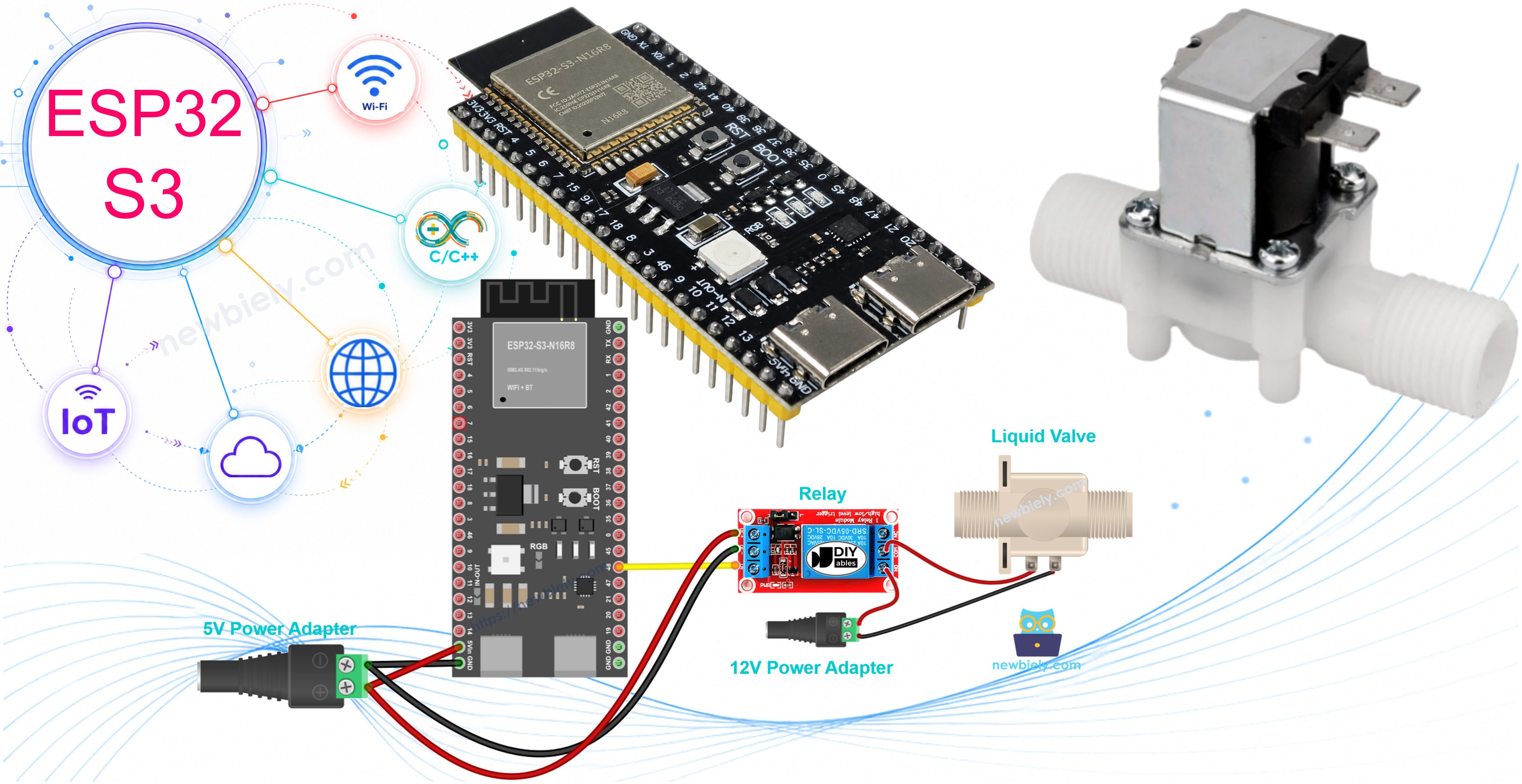
Hardware Preparation
Or you can buy the following kits:
| 1 | × | DIYables ESP32 S3 Starter Kit (ESP32 S3 included) | |
| 1 | × | DIYables Sensor Kit (18 sensors/displays) |
Additionally, some of these links are for products from our own brand, DIYables .
Overview of Water/Liquid Valve
A solenoid valve is an electromechanical device that uses an electric signal to open or close a flow path for liquids or gases. When voltage is applied, an internal electromagnet pulls a plunger to open the valve; removing power allows a spring to close it again. This simple on/off mechanism makes solenoid valves an ideal choice for automating irrigation, dispensing, and flow control systems with a microcontroller like the ESP32 S3.
Key Specifications
- Operating Voltage: Typically 12V DC (some models use 5V or 24V)
- Flow Control: Opens when powered, closes when power is removed
- Applications: Water dispensing, irrigation, gas control, beverage systems
- Flow Direction: Some valves are unidirectional (check valve specifications)
- Pressure Requirements: Some models need minimum pressure to fully open
- Perfect for beginners: Simple on/off control makes automation projects easy
Pinout
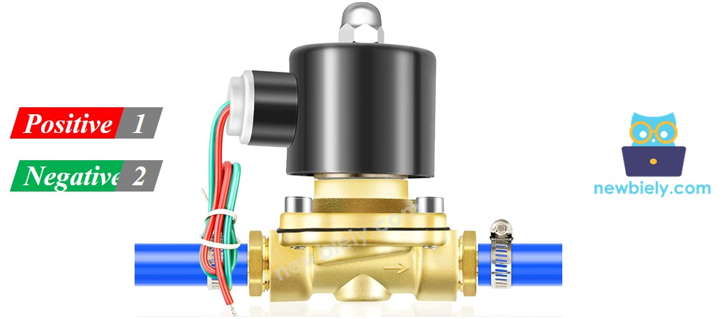
The solenoid valve exposes two connection terminals that carry the switched 12V supply:
- Positive (+) pin (red): Connect to 12V DC power supply positive terminal
- Negative (-) pin (black): Connect to 12V DC power supply ground (via relay control)
How Water/Liquid Valve Works
The valve operates on a simple electromagnetic principle:
- Default State: Valve is normally closed, blocking liquid/gas flow
- Powered State: When 12V DC is applied, electromagnet pulls valve open
- Flow Control: Liquid/gas flows freely when valve is open
- Return to Closed: Removing power closes the valve automatically
※ NOTE THAT:
- Some valves require minimum water pressure to fully open after power is applied - the pressure is created by the liquid flow itself
- Many solenoid valves are directional - liquid can only flow one way (check the arrow marking on valve body)
- Always verify the voltage rating before connecting power to avoid damaging the valve
How to Control Water/Liquid Solenoid Valve
Controlling a solenoid valve with the ESP32 S3 requires a relay module because the ESP32 S3 GPIO pins output only 3.3V at low current, while most solenoid valves need 12V at significantly higher current. The relay acts as an electronically controlled switch: the ESP32 S3 drives the relay coil with a small signal, and the relay's internal contacts switch the full 12V supply to the valve. This arrangement also electrically isolates the ESP32 S3 from the high-power valve circuit, protecting the microcontroller. For a deeper look at relay operation, see our ESP32 S3 - Relay tutorial.
A MOSFET module is a quiet alternative to the relay. If you have never used one, the ESP32 S3 - MOSFET Module tutorial covers its pins and wiring.
Relay or MOSFET Module for a Solenoid Valve
| Topic | Relay | MOSFET Module |
|---|---|---|
| Valve control | open / closed | open / closed (a valve should never get PWM) |
| Noise | click from the relay, plus the valve | only the valve itself |
| Switching | slower, a few milliseconds | very fast |
| Wear | relay contacts wear out over time | no moving parts in the module |
| Valve type | AC or DC valves | DC valves only |
| Valve voltage | any the relay can handle | 6V or more |
| Isolation | yes (coil and contacts) | yes (PC817 optocoupler) |
| Pick it for | AC valves, simple projects | 12V DC valves that open and close many times a day |
Both give the same open/close result. Use the MOSFET module for a 12V DC valve that switches often, such as in a watering system, because it is silent and lasts longer. Use the relay for AC valves.
Wiring Diagram
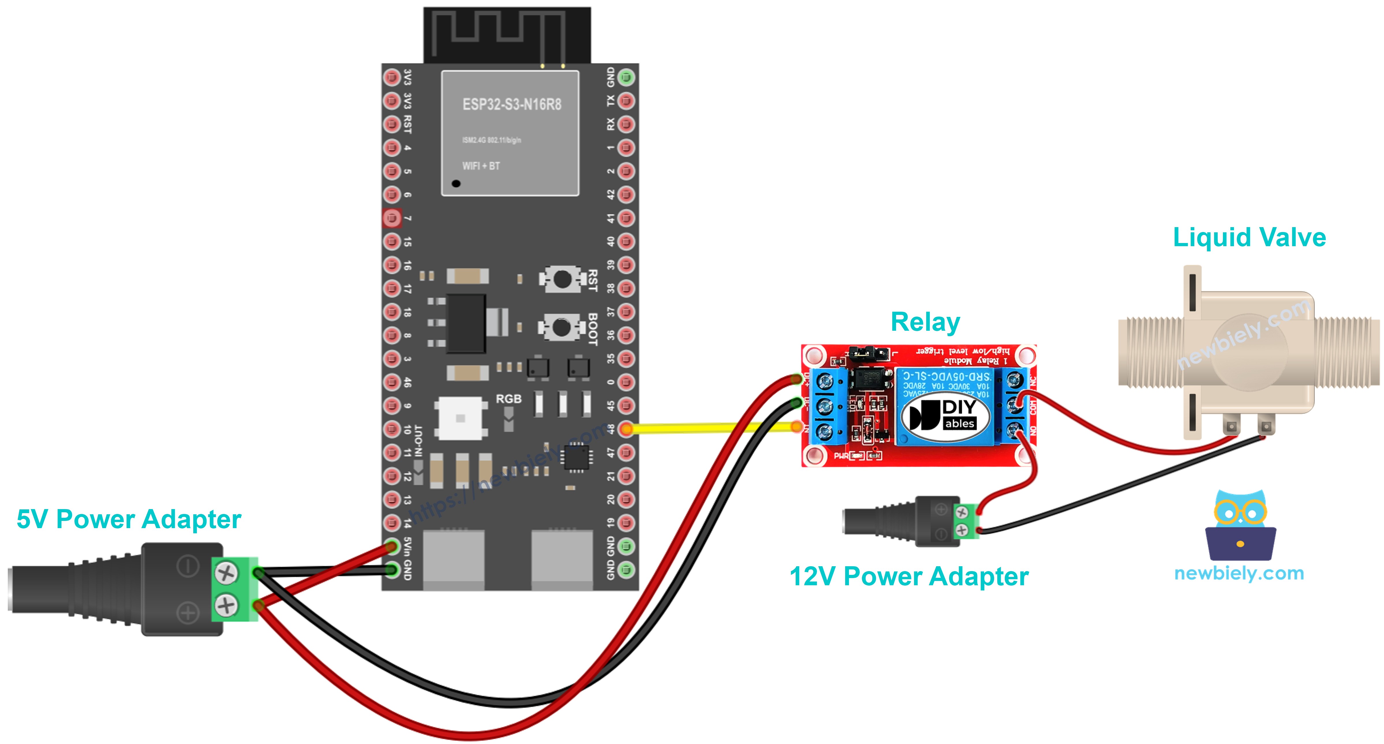
This image is created using Fritzing. Click to enlarge image
Follow the wiring diagram above to connect your ESP32 S3 to the relay and solenoid valve. Keep signal wires away from the 12V side to minimise noise and reduce risk.
Safety Notes
Never connect the 12V power supply directly to any ESP32 S3 GPIO pin — the relay exists specifically to bridge the voltage gap. Before powering on, double-check polarity on both the relay module and the valve terminals. Ensure all screw terminals and Dupont connections are firmly seated to prevent intermittent switching that could damage the valve coil over time.
Wiring Connections:
| Component Pin | Arduino Pin | Notes |
|---|---|---|
| Relay Signal Pin | D7 | Control signal from ESP32 |
| Relay VCC | 5V | Power for relay module |
| Relay GND | GND | Common ground |
| Relay COM | 12V Power (+) | 12V input to relay switch |
| Relay NO | Valve (+) | Normally Open to valve positive |
| Valve (-) | 12V Power GND | Valve negative to power ground |
ESP32 S3 Code
The following code demonstrates automatic valve control using the ESP32 S3 — it opens the solenoid valve for 5 seconds, then closes it for 5 seconds in a continuous cycle. Serial output lets you confirm the valve state in real time without needing a multimeter or oscilloscope. Copy the sketch into a new Arduino IDE project, select the correct board and port, then upload.
Detailed Instructions
- New to ESP32 S3? Complete our Getting Started with ESP32 S3 guide first.
- Install Arduino IDE: Follow the ESP32 S3 software installation guide if you haven't set up the board package yet.
- Wire the components: Connect the relay and solenoid valve to the ESP32 S3 following the wiring diagram above.
- Connect USB cable: Plug your ESP32 S3 into your computer using a USB Type-C cable.
- Open Arduino IDE: Launch the Arduino IDE application on your computer.
- Select your board: Choose ESP32 S3 from the board menu.
- Select COM port: Pick the correct COM port that your ESP32 S3 is connected to.
- Copy the code: Copy the provided code and paste it into a new Arduino IDE sketch.
- Upload the code: Click the Upload button to compile and upload code to your ESP32 S3.
- Test the valve: Observe the valve opening and closing every 5 seconds, and check water flow if connected.
- Pro Tip: Open the Serial Monitor at 115200 baud to see real-time valve status messages — this is the fastest way to confirm the relay is firing correctly before connecting the 12V supply.
Code Explanation
The ESP32 S3 code includes detailed line-by-line comments explaining each function. Read through the code comments to understand how valve control works!
Key code concepts:
- Pin Configuration: Sets up D7 as an output pin to control the relay
- digitalWrite() Function: Sends HIGH or LOW signals to open/close the valve
- delay() Function: Creates 5-second timing intervals between valve operations
- Serial Monitor: Prints valve status for debugging and monitoring
Serial Monitor Output
Open the Serial Monitor at 115200 baud rate to see the valve operation status:
Application and Project Ideas
The ESP32 S3's wireless capabilities and processing power make it an excellent controller for liquid automation systems across a wide range of domains.
- Smart Garden Irrigation: Automate watering schedules based on soil moisture or time intervals.
- Pet Water Dispenser: Create an automatic water bowl refill system for pets.
- Coffee Machine Automation: Control water flow for DIY espresso or drip coffee makers.
- Aquarium Auto-Fill System: Maintain constant water levels in fish tanks automatically.
- Homebrew Beer Dispenser: Build a controlled beer tap system with precise flow control.
- Car Wash System: Automate water spray timing for DIY vehicle cleaning stations.
- Hydroponics Nutrient Feeder: Control nutrient solution flow in soilless growing systems.
How to Control Water/Liquid Valve with MOSFET Module
You can remove the relay and switch the valve with a MOSFET module. The valve still only opens and closes, but now there is no relay click.
The relay and the MOSFET module use different pins on this page. The relay uses D7 (GPIO7), and the MOSFET module uses GPIO47. So each wiring has its own code.
Wiring Diagram with MOSFET Module
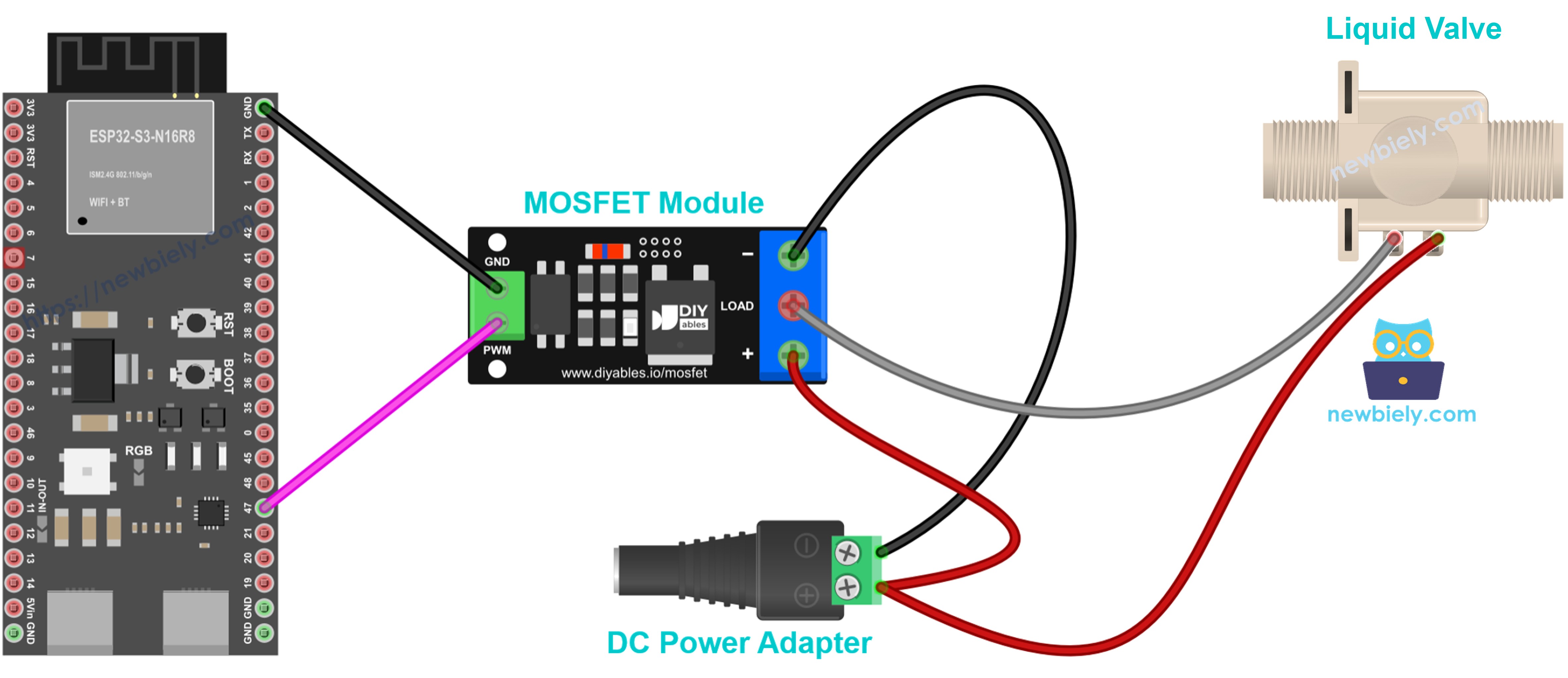
This image is created using Fritzing. Click to enlarge image
| From | To | Notes |
|---|---|---|
| ESP32 S3 GPIO47 | Module PWM | control signal |
| ESP32 S3 GND | Module GND | signal ground |
| 12V Power (+) | Module + | power in |
| Valve (+) | Module + | shares the screw with 12V Power (+) |
| Valve (-) | Module LOAD | switched by the MOSFET |
| 12V Power GND | Module − | power ground |
The valve has a coil inside. Add a flyback diode (1N4007 or 1N5819) across the valve terminals, with the stripe (cathode) on valve +.
ESP32 S3 Code for MOSFET Module
The code works like the relay code: HIGH turns the valve ON (open) and LOW turns it OFF (closed). The valve opens for 5 seconds, closes for 5 seconds, and repeats. This sketch has no Serial output.
A solenoid valve must only get full ON or full OFF. Never drive it with PWM. That is why this page does not use the fade code from the MOSFET module tutorial.
Detailed Instructions
- Wire the components: Connect the MOSFET module, the valve and the 12V supply as shown in the diagram above.
- Connect USB cable: Plug your ESP32 S3 into your computer.
- Open Arduino IDE: Select the board and COM port, as in the relay Quick Steps above.
- Upload the code: Copy the code above into a new sketch and click Upload.
- Test the valve: Listen and watch: the valve opens for 5 seconds and closes for 5 seconds, with no relay click.
Tip: The MOSFET module is for DC only and needs a valve supply of at least about 6V. Keep the relay for AC valves.
Video Tutorial
Watch the step-by-step video walkthrough for this ESP32 S3 project below.
...VIDEO /videos/placeholder.mp4
...VIDEO
Challenge Yourself
Once the basic valve cycle is working, these challenges will push your ESP32 S3 skills further and result in genuinely useful automation projects.
- Beginner: Add a push button to manually open/close the valve instead of relying on automatic timing.
- Beginner: Change the timing — make the valve open for 10 seconds and close for 3 seconds.
- Intermediate: Add a soil moisture sensor to open the valve only when soil is dry (smart irrigation).
- Intermediate: Use a potentiometer to adjust how long the valve stays open (variable flow duration).
- Advanced: Build a web server so you can control the valve remotely from your phone browser using the ESP32 S3's built-in Wi-Fi.
- Advanced: Create a scheduled watering system using the ESP32 S3 real-time clock (RTC) to trigger the valve at specific times each day.