
ESP32 S3 - RS485
RS485 (also known as RS-485) is a widely used serial communication standard designed for long-distance, noise-resistant data transmission in industrial and embedded systems. In this tutorial, you will learn how to use RS485 communication with the ESP32 S3 by connecting it to a TTL to RS485 module and programming it to send and receive data.
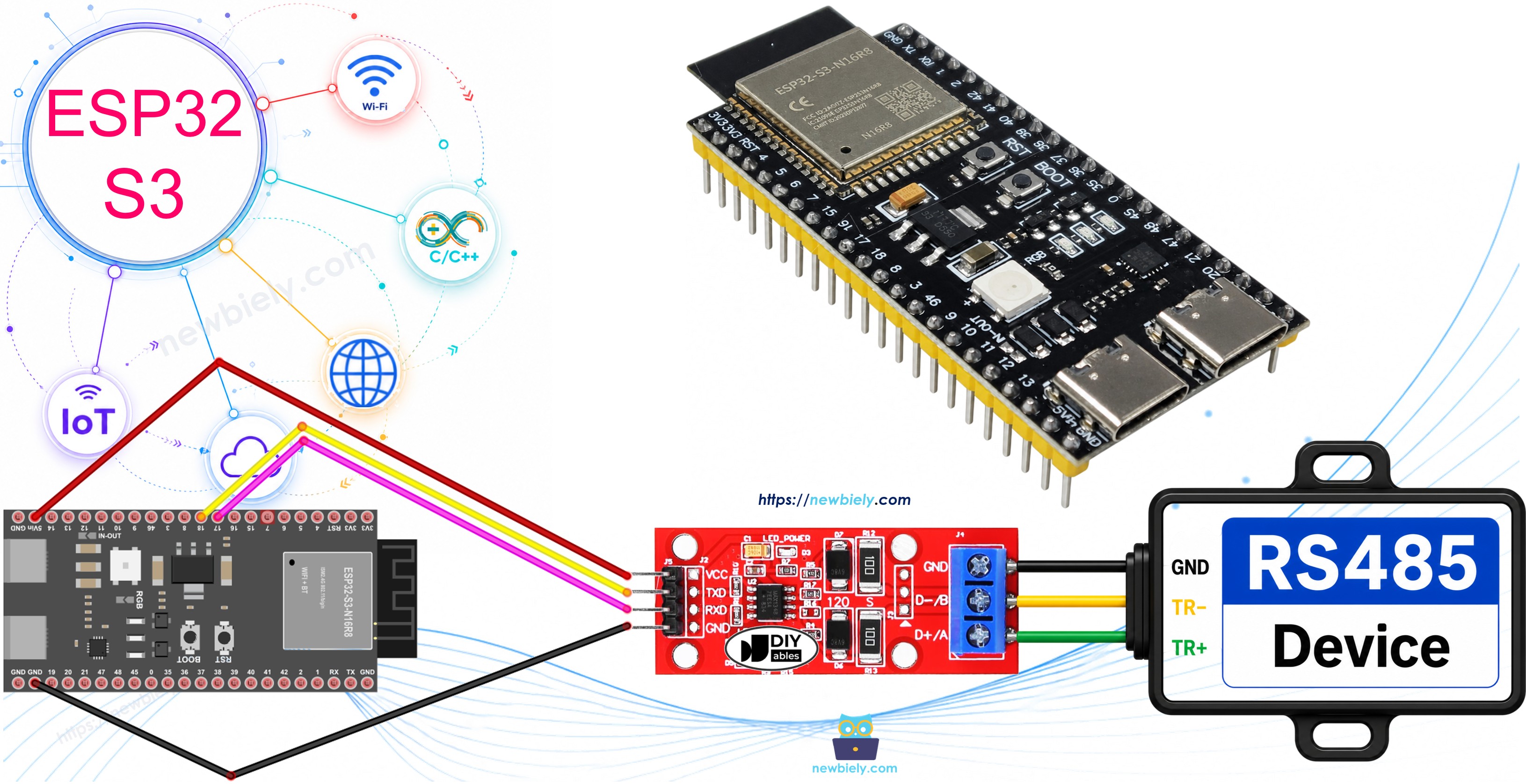
What you'll build:
- A wired connection between the ESP32 S3 and a TTL to RS485 module.
- ESP32 S3 code that initializes the RS485 serial interface.
- A test setup that sends data from your PC to the ESP32 S3 via RS485, and receives the echo back.
- A working RS485 communication link suitable for industrial or long-distance serial applications.
Hardware Preparation
Or you can buy the following kits:
| 1 | × | DIYables ESP32 S3 Starter Kit (ESP32 S3 included) | |
| 1 | × | DIYables Sensor Kit (18 sensors/displays) |
Additionally, some of these links are for products from our own brand, DIYables .
Overview of TTL to RS485 Module
When utilizing serial communication on the ESP32 S3 with functions such as Serial.print(), Serial.read(), and Serial.write(), data transmission occurs via the TX pin while data reception happens through the RX pin. These pins operate at TTL level, meaning they handle signals with a limited voltage range, which makes them unsuitable for long-distance communication without conversion. To send data over extended distances, it is necessary to convert the TTL signal to a robust standard such as RS485, which supports cable runs of up to 1200 meters and multi-device bus topologies.
In this tutorial, you will use a TTL to RS485 module that handles the signal conversion automatically in both directions, allowing the ESP32 S3 to communicate over an RS485 bus without any additional hardware complexity.
Key Specifications
- Interface: TTL (3.3V/5V compatible) on one side, RS485 differential pair on the other
- Maximum Cable Length: Up to 1200 meters
- Maximum Baud Rate: Up to 10 Mbps (module dependent)
- Bus Devices: Supports up to 32 nodes on a single RS485 bus
- Common ICs: MAX13487, MAX3485, SP3485
Pinout
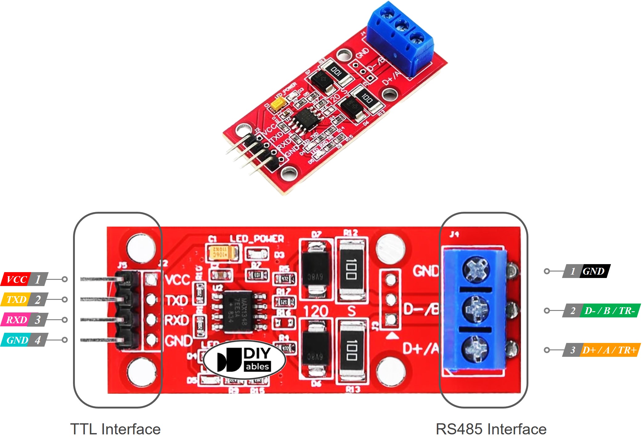
The RS485 to TTL module features two interfaces:
- TTL Interface (connected to ESP32 S3):
- VCC Pin: This power pin should be connected to VCC (5V or 3.3V).
- GND Pin: This power pin should be connected to GND (0V).
- RXD Pin: This data pin should be connected to a TX pin of the ESP32 S3.
- TXD Pin: This data pin should be connected to an RX pin of the ESP32 S3.
- D+ (A or TR+) Pin: This pin facilitates data communication.
- D- (B or TR-) Pin: This pin is utilized for data transmission.
- GND Pin: While optional, including this pin is strongly recommended to mitigate noise interference, ensuring optimal performance.
Wiring Diagram
Connect the TTL to RS485 module to your ESP32 S3 as shown in the diagram below. Use short, reliable jumper wires for the TTL side and twisted-pair cable for the RS485 differential pair to minimize noise.
Safety Notes
Keep the RS485 differential pair (D+/D-) away from power lines and high-frequency signals. Always connect the RS485 GND between devices to provide a common reference and reduce common-mode noise. Do not exceed the module's rated VCC voltage.
| TTL to RS485 Module | ESP32 S3 |
|---|---|
| VCC | 3.3V |
| GND | GND |
| RXD | TX2 (GPIO17) |
| TXD | RX2 (GPIO18) |
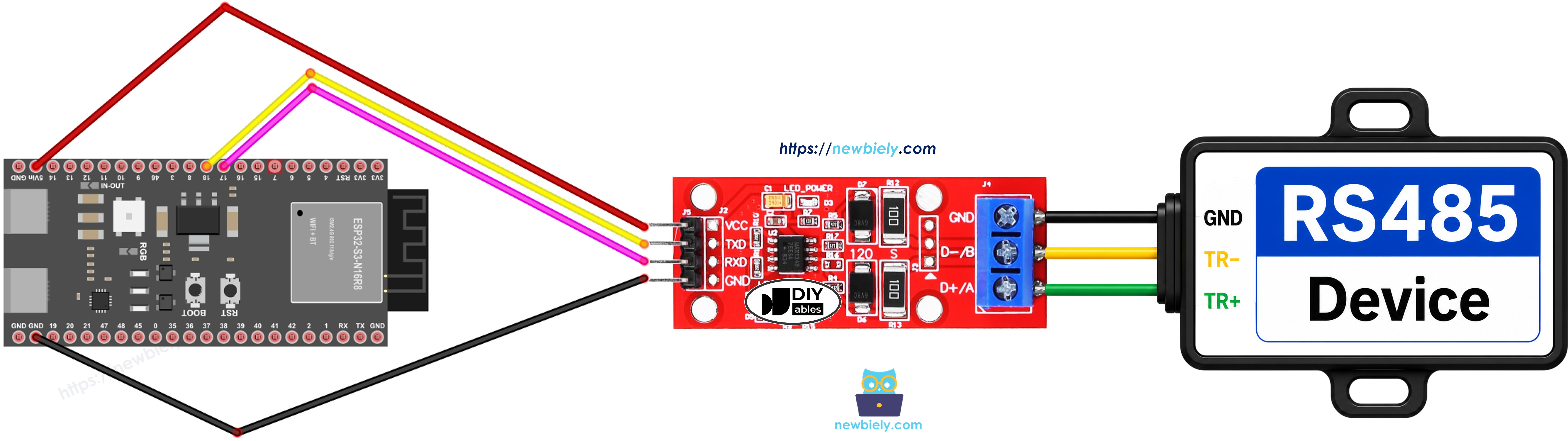
This image is created using Fritzing. Click to enlarge image
How To Program ESP32 S3 to use the RS485 module
Programming the ESP32 S3 to communicate over RS485 is straightforward because the TTL to RS485 module handles all signal conversion transparently. You simply initialize the hardware serial port on the ESP32 S3 and then use standard Serial functions to send and receive data, exactly as you would for any UART-based communication.
The following code shows how to initialize the serial interface for RS485 communication:
- Initializes the Serial interface:
- To read data come from RS485, you can use the following functions:
- To write data to RS485, you can use the following functions:
- And more functions to use with RS485 in Serial reference
ESP32 S3 Code
The following code demonstrates a complete RS485 echo example for the ESP32 S3. Any data received on the RS485 bus is immediately echoed back, making it easy to test two-way communication from a PC terminal.
Detailed Instructions
Follow these steps to set up and test RS485 communication with your ESP32 S3:
- New to ESP32 S3? Complete our Getting Started with ESP32 S3 guide first.
- Wire the TTL to RS485 module to the ESP32 S3 following the wiring diagram above.
- Connect the ESP32 S3 to your PC via the USB Type-C cable.
- Open the Arduino IDE and paste in the ESP32 S3 code shown above.
- Select the correct board and COM port in the Arduino IDE Tools menu.
- Click Upload to flash the code onto the ESP32 S3.
- Connect the RS485 D+/D- lines to a USB-to-RS485 converter attached to your PC.
- Type some text in the terminal and press Enter — if everything is wired correctly, you will see the echoed data returned from the ESP32 S3.
- Pro Tip: Use a twisted-pair cable for the RS485 D+/D- lines and add a 120-ohm termination resistor at each end of the bus to prevent signal reflections at higher baud rates or longer cable runs.
Serial Monitor
Open the Arduino IDE Serial Monitor (set to 9600 baud) to observe activity on the ESP32 S3 side. You should see output similar to the following:
Testing
You can perform a full end-to-end test by sending data from your PC to the ESP32 S3 via RS485 and observing the echo response. Connect the ESP32 S3 to your PC via a USB-to-RS485 cable as shown below, configure your serial terminal to match the baud rate in the code, and type data into the terminal.
- Connect the ESP32 S3 RS485 output to your PC via a RS485-to-USB cable as below:
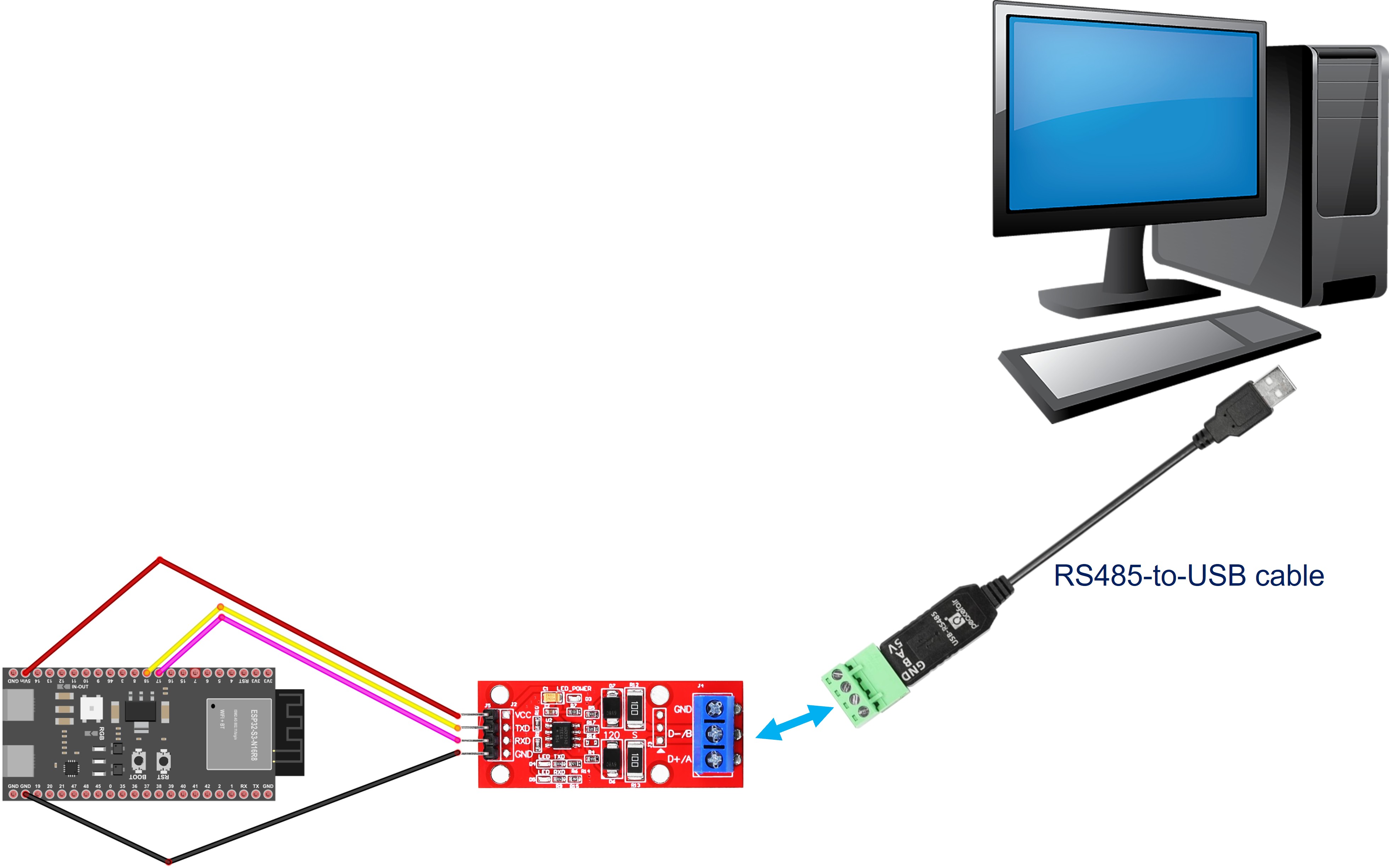
- Open the Serial Terminal Program and configure the Serial parameters (COM port, baud rate...)
- Type some data from the Serial Terminal to send it to the ESP32 S3.
- If successful, you will see the echo data on the Serial Terminal.
Applications
RS485 is a versatile communication standard well-suited for a wide range of professional and industrial use cases where reliability and cable length matter.
- Industrial Automation: Connect the ESP32 S3 to PLCs, sensors, and actuators on a factory RS485 bus for data acquisition and control.
- Building Management Systems: Use the ESP32 S3 as an RS485 node to interface with HVAC controllers, lighting systems, and energy meters.
- Multi-Device Networks: Implement a multi-drop RS485 bus with up to 32 devices, each addressed individually by the ESP32 S3 master.
- Long-Distance Serial Links: Replace short-range USB or TTL connections with RS485 for reliable communication over runs up to 1200 meters.
- Modbus RTU Protocol: Use the ESP32 S3 with an RS485 module as a Modbus RTU master or slave to communicate with industrial instruments.
Video Tutorial
Watch the step-by-step video walkthrough for this ESP32 S3 project below.
Challenges
These challenges will help you deepen your understanding of RS485 communication with the ESP32 S3 and explore more advanced use cases.
- Beginner: Modify the code to add a timestamp prefix to each echoed message, so you can track when data was received.
- Intermediate: Implement a simple Modbus RTU frame parser on the ESP32 S3 that reads a holding register request and returns a valid response over RS485.
- Advanced: Build a multi-node RS485 network with two or more ESP32 S3 boards, each with a unique address, and implement a master-slave protocol where the master polls each slave in round-robin fashion.