
ESP32 S3 - Light Sensor
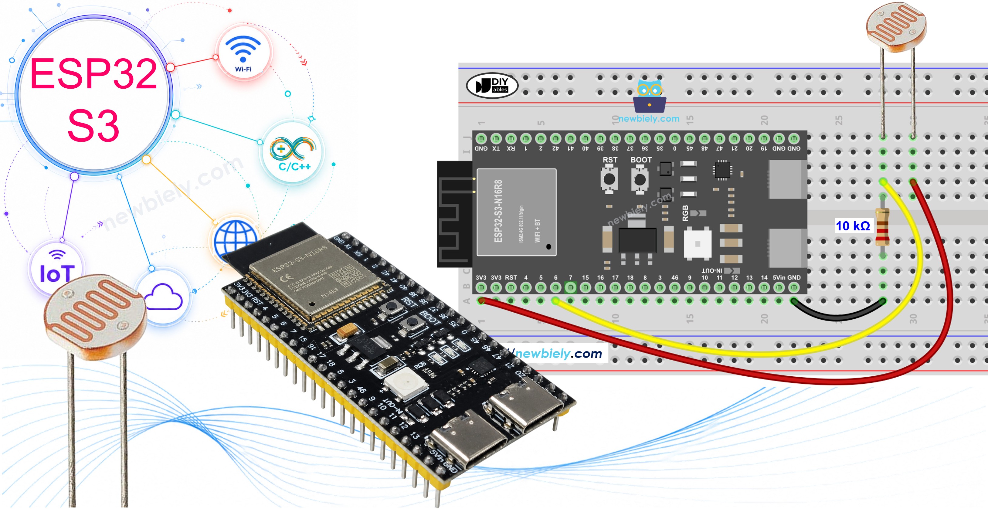
Learn how to connect a light sensor (photoresistor/LDR) to your ESP32 S3 and read light levels in your Arduino projects. This beginner-friendly guide covers everything from wiring to code, helping you build your first ambient light detection system with ESP32 S3.
What you'll build:
- A light sensor circuit connected to the ESP32 S3 analog input
- Arduino code that reads and categorizes ambient light levels
- A Serial Monitor display showing real-time brightness values
- An automatic LED controller that responds to changing light conditions
Hardware Preparation
Or you can buy the following kits:
| 1 | × | DIYables ESP32 S3 Starter Kit (ESP32 S3 included) | |
| 1 | × | DIYables Sensor Kit (18 sensors/displays) |
Additionally, some of these links are for products from our own brand, DIYables .
Component Options:
The LDR light sensor is very affordable, but it requires a resistor for wiring, which can make the setup more complex. To simplify the wiring, you can use an LDR light sensor module as an alternative.
Overview of Light Sensor
A light sensor (photoresistor) is an analog component that changes its resistance based on the amount of light hitting its surface. It is one of the simplest and most affordable sensors you can use with a microcontroller like the ESP32 S3, making it ideal for beginner projects. Common applications range from automatic night lights to plant light monitors and smart home systems.
Key Specifications
The photoresistor is also known as a photocell or light-dependent resistor (LDR). Its resistance typically ranges from around 200 Ω in bright light conditions down to as low as 200 Ω, and climbs up to 10 MΩ in complete darkness. The response time is approximately 20–30 ms, making it well-suited for sensing gradual changes in ambient light. It operates using a simple voltage divider circuit and outputs an analog signal that the ESP32 S3 can read directly through its ADC pins.
Light Sensor Pinout
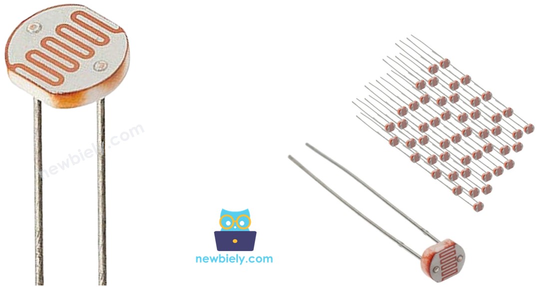
The photoresistor has two non-polarized pins that can be connected in either orientation.
- Pin 1: Connect to either side of the voltage divider
- Pin 2: Connect to either side of the voltage divider
Note: Unlike LEDs or diodes, light sensor pins are interchangeable—you don't need to worry about polarity.
How Light Sensor Works
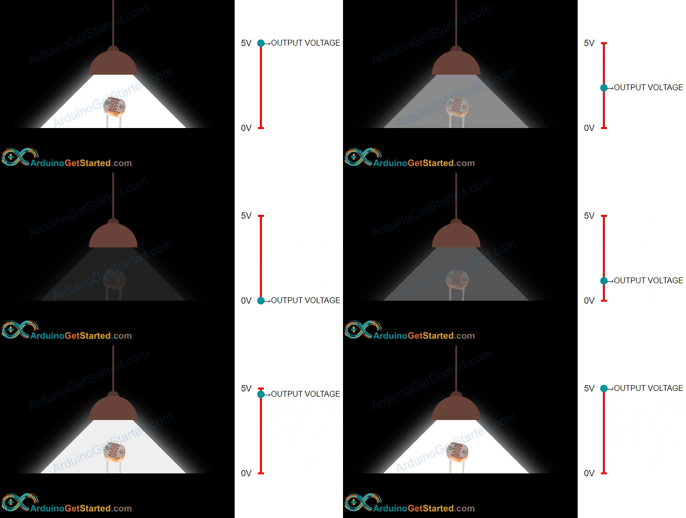
The photoresistor's resistance changes inversely with light intensity—more light means less resistance, which produces a higher voltage at the ESP32 S3 analog pin. The ESP32 S3 reads that voltage and converts it to a digital value between 0 and 4095 using its built-in ADC. Higher analog values indicate brighter conditions, while lower values indicate darker environments.
WARNING
The value measured by photoresistor reflects the approximated tendency of the light's intensity, it does NOT represent exactly the luminous flux. Therefore, the photoresistor should not be used in an application that requires high accuracy. calibration is also required for some kind application.
ESP32 S3 - Light Sensor
The ESP32 S3 reads light sensor values through its analog input pins. The ESP32 S3's ADC converts an input voltage ranging from 0 V to 3.3 V into an integer value between 0 and 4095, which is known as the ADC value. You use the analogRead() function to retrieve this value—higher ADC readings correspond to brighter light conditions, while lower readings indicate darker environments.
Wiring Diagram between Light Sensor and ESP32 S3
Connect the light sensor to your ESP32 S3 using a voltage divider circuit with a 10 kΩ resistor. One leg of the photoresistor connects to 3.3 V, while the other leg connects both to a GPIO analog pin and to one end of the 10 kΩ resistor, with the resistor's other end going to GND.
Safety Notes
Always double-check your connections before powering on the board. Ensure the resistor value is 10 kΩ, since using the wrong resistor value will affect the voltage divider ratio and produce inaccurate ADC readings.
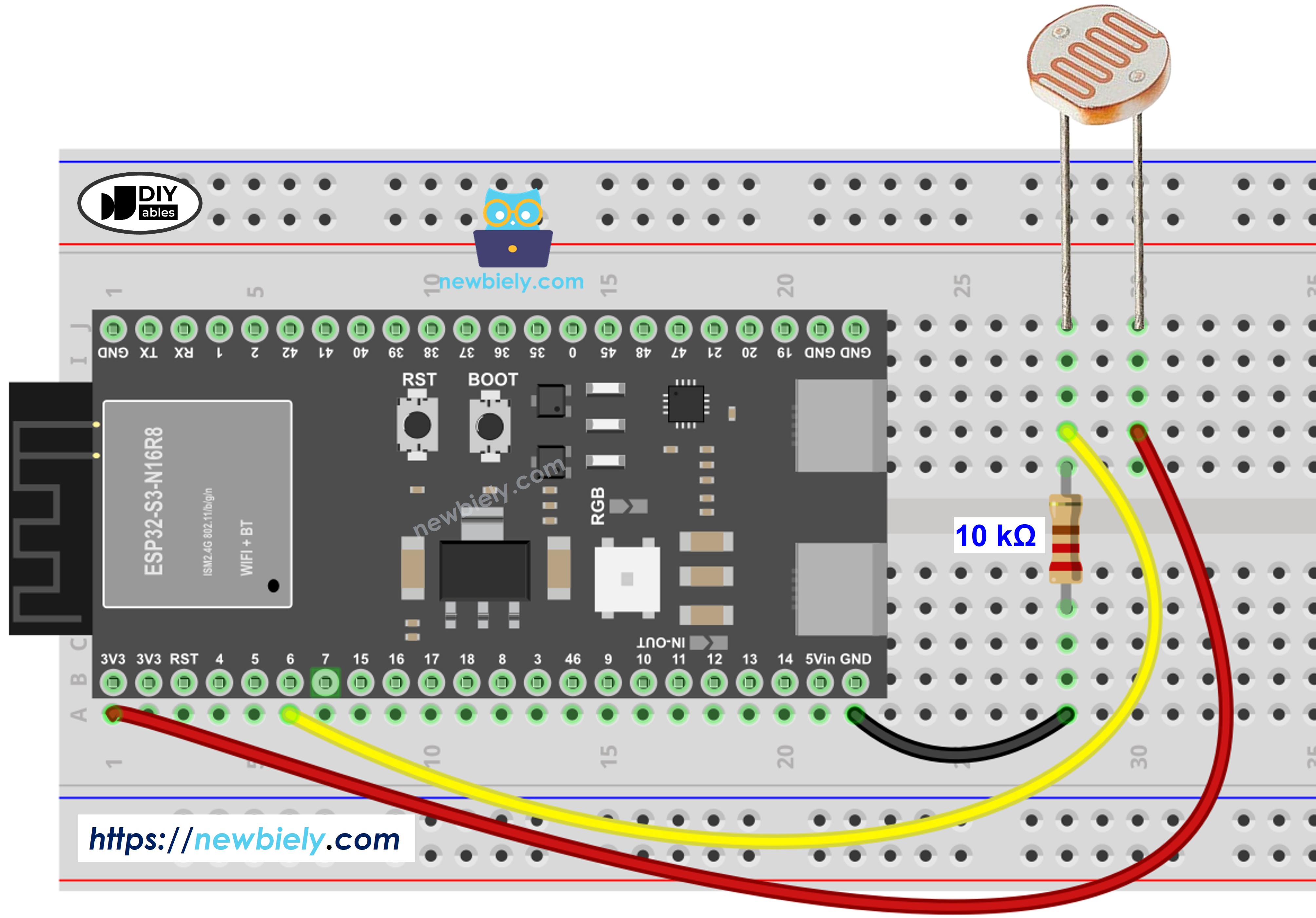
This image is created using Fritzing. Click to enlarge image
| Light Sensor Pin 1 | 3.3V |
|---|---|
| Light Sensor Pin 2 | GPIO6 (Analog Pin) + 10kΩ Resistor |
| 10kΩ Resistor (Other End) | GND |
ESP32 S3 Code
The following code reads the analog value from the light sensor connected to GPIO6 on the ESP32 S3 and categorizes the brightness into one of four levels. It prints both the raw ADC value and the corresponding label to the Serial Monitor every 500 milliseconds, making it easy to observe how the sensor responds to changing light conditions in real time.
Detailed Instructions
- New to ESP32 S3? Complete our Getting Started with ESP32 S3 guide first.
- Copy the Code: Copy the code above and paste it into Arduino IDE.
- Select Board: Make sure ESP32 S3 is selected in Tools > Board.
- Connect ESP32: Plug your ESP32 S3 into your computer via USB Type-C cable.
- Upload Code: Click the Upload button in Arduino IDE.
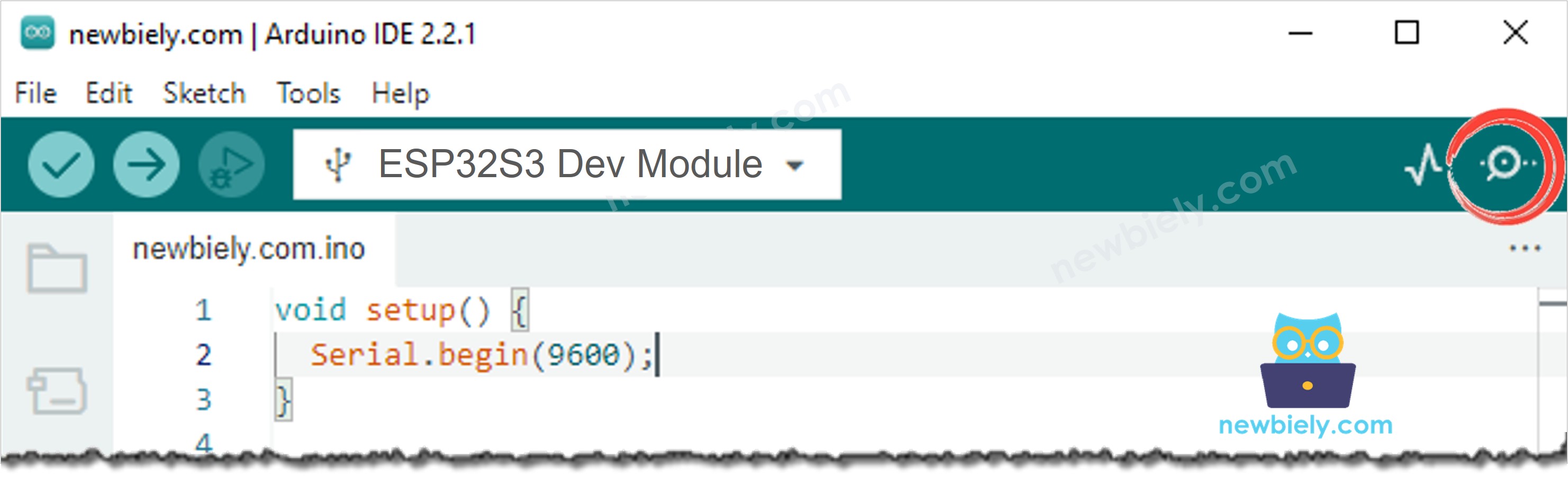
- Open Serial Monitor: Click the Serial Monitor icon or press Ctrl+Shift+M.
- Set Baud Rate: Set Serial Monitor to 115200 baud.
- Test the Sensor: Cover the light sensor with your hand, then expose it to bright light.
- Observe Results: Watch the analog values and light level descriptions change in real-time.
- Pro Tip: The threshold values (1000, 2000, 3000) can be adjusted based on your ambient light conditions for more accurate readings.
Expected Serial Monitor Output:
Light Sensor and LED
Now let's create an automatic lighting system that turns on an LED when it gets dark.
Wiring Diagram
Add an LED to your circuit to create a light-activated switch.
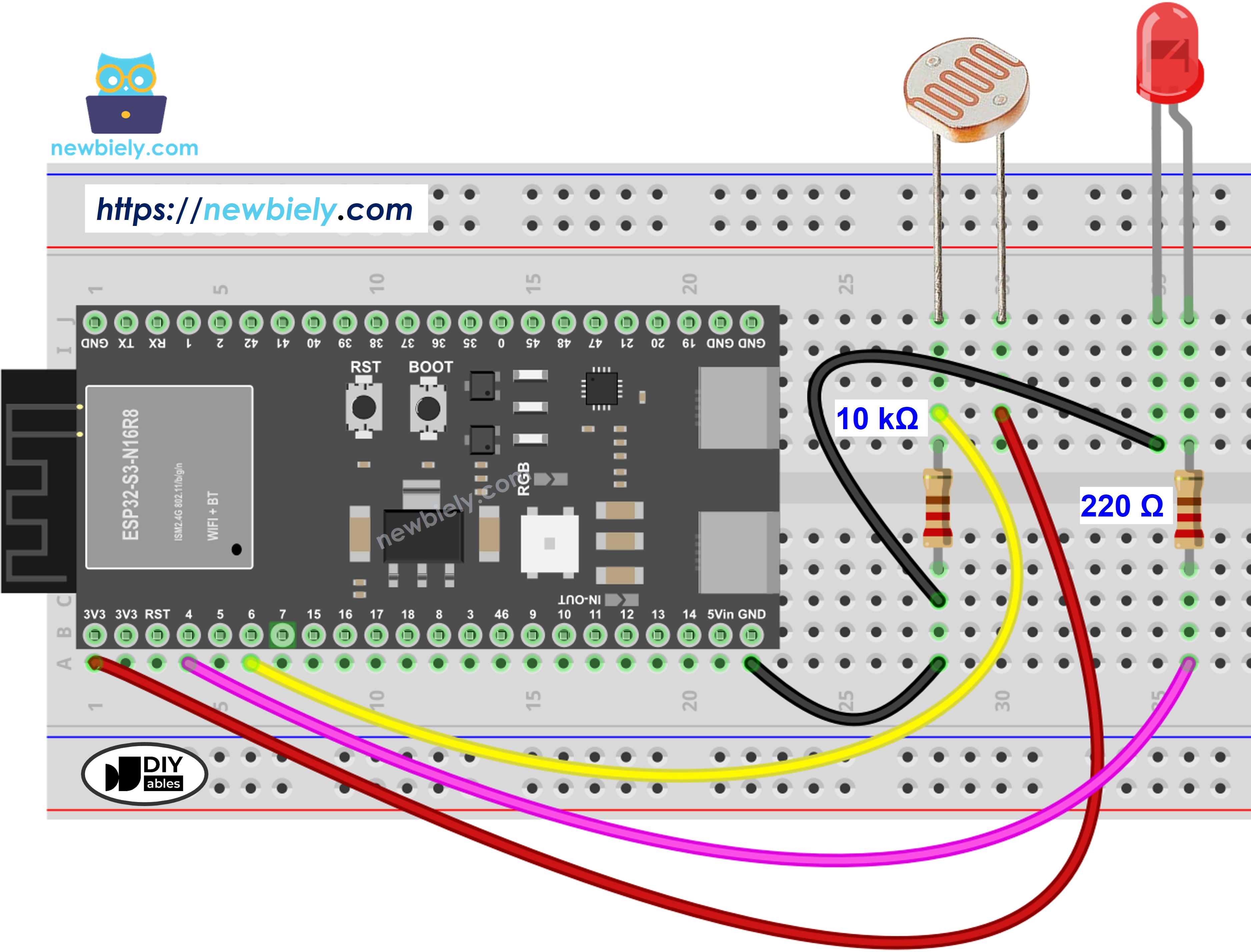
This image is created using Fritzing. Click to enlarge image
Additional Connections:
| LED Anode (Long Leg) | GPIO8 (through 220Ω resistor) |
|---|---|
| LED Cathode (Short Leg) | GND |
ESP32 S3 Code
The following code reads the light sensor continuously and compares each reading against a fixed threshold. When the ambient light drops below the threshold, the ESP32 S3 turns the LED on automatically; when sufficient light returns, it turns the LED off—creating a simple and effective automatic night light.
※ NOTE THAT:
This tutorial uses the analogRead() function to read values from an ADC (Analog-to-Digital Converter) connected to a sensor or component. The ESP32 S3's ADC is suitable for projects that do not require high accuracy. However, for projects needing precise measurements, keep the following in mind:
- The ESP32 S3's ADC is not perfectly accurate and might require calibration for correct results. Each ESP32 S3 board can vary slightly, so calibration is necessary for each individual board.
- Calibration can be challenging, especially for beginners, and might not always yield the exact results you want.
For projects requiring high precision, consider using an external ADC (e.g ADS1115) with the ESP32 S3 or using another Arduino, such as the Arduino Uno R4 WiFi, which has a more reliable ADC. If you still want to calibrate the ESP32 S3's ADC, refer to the ESP32 ADC Calibration Driver.
Application and Project Ideas
Now that you know how to use a light sensor with ESP32 S3, there are many practical ways to put this knowledge to work in real-world projects.
- Automatic Night Light: LED turns on automatically when the room gets dark.
- Smart Plant Monitor: Track sunlight exposure for your indoor plants throughout the day.
- Security System: Detect when lights turn on or off in a room to trigger alerts.
- Weather Station: Monitor daylight hours and cloud coverage as part of a broader sensor array.
- Energy Saver: Automatically control window blinds based on sunlight intensity.
- Photography Light Meter: Measure ambient light levels to assist with camera settings.
Video Tutorial
Watch the step-by-step video walkthrough for this ESP32 S3 project below.
Challenge Yourself
Once you have the basic light sensor working with your ESP32 S3, try pushing your skills further with these progressive challenges.
- Beginner: Add a buzzer that beeps once when the light level transitions from bright to dark.
- Beginner: Display "Good morning!" on the Serial Monitor when light is detected and "Good night!" when it's dark.
- Intermediate: Create a data logger that records light levels every minute and stores them on an SD card.
- Intermediate: Build a smart curtain controller that opens or closes based on simulated sunrise and sunset thresholds.
- Advanced: Implement a solar panel tracker that monitors light intensity from multiple sensors and rotates a servo to follow the light source.
- Advanced: Create a greenhouse automation system that uses light-based logic to control watering schedules and ventilation fans.