
ESP32 S3 - DIP Switch
DIP (Dual In-line Package) switches are widely used in electronics for configuration purposes, such as setting device addresses, enabling or disabling features, and defining operation modes. In this tutorial, you will learn how to connect and use a DIP switch with the ESP32 S3 board.
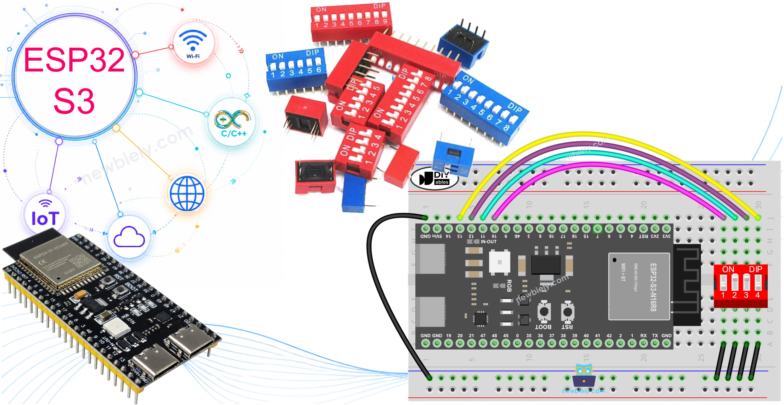
What you'll build:
- Read the ON/OFF state of each individual position on the DIP switch
- Encode all DIP switch positions into a single integer value
- Display the results in real time via the Arduino Serial Monitor
- Apply the technique to any 2- to 10-position DIP switch
Hardware Preparation
Or you can buy the following kits:
| 1 | × | DIYables ESP32 S3 Starter Kit (ESP32 S3 included) | |
| 1 | × | DIYables Sensor Kit (18 sensors/displays) |
Additionally, some of these links are for products from our own brand, DIYables .
Overview of DIP Switch
DIP switches serve as fundamental components for device configuration, enabling users to adjust parameters such as device addresses, communication settings, security codes, operation modes, and system preferences across many industries and applications. Each position on a DIP switch corresponds to a single bit of a configurable binary number, making them a compact and reliable way to set hardware options without software. By toggling positions between ON and OFF, you can precisely define numeric values and feature flags that the ESP32 S3 reads at startup or during operation.
Key Specifications
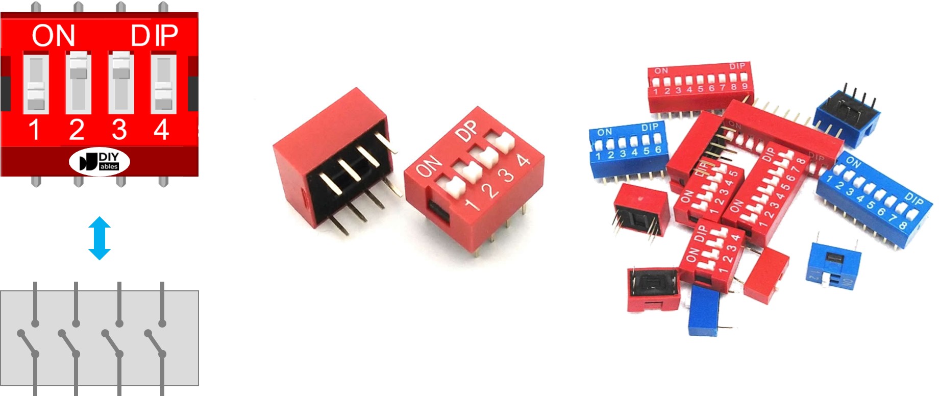
A DIP switch comprises multiple small slide switches grouped together, with each individual switch called a "position." DIP switches are available in 2-position, 4-position, 5-position, 6-position, 8-position, and 10-position variants. Each position on a DIP switch corresponds to one bit of a configurable number, and toggling positions between ON and OFF allows you to set a desired numeric value with high precision.
Pinout
A DIP switch is composed of dual rows of pins, with the number of pins in each row matching the number of switch positions.
- Two rows of pins — one row per side of the switch body
- A 4-position DIP switch has 8 pins total (4 per side)
- Every pair of opposing pins forms one slide switch
- The pins on both sides are interchangeable — polarity does not matter
How It Works
When a switch position is ON, the circuit between the two corresponding pins is closed, allowing current to flow. When a position is OFF, the circuit is open and current cannot flow.
Safety Notes
Connect one side of each switch position to GND and the other side to an ESP32 S3 GPIO pin configured as a pull-up digital input. This keeps the pin in a known HIGH state when the switch is open, and pulls it LOW when the switch is closed.
| DIP switch position | Binary representation | Circuit state | ESP32 S3 pin state |
|---|---|---|---|
| ON | 1 | CLOSED | LOW |
| OFF | 0 | OPEN | HIGH |
In the sections below, a 4-position DIP switch is used as the example. You can easily adapt the code and wiring for 2-position, 3-position, 5-position, 6-position, 8-position, and 10-position DIP switches.
Wiring Diagram
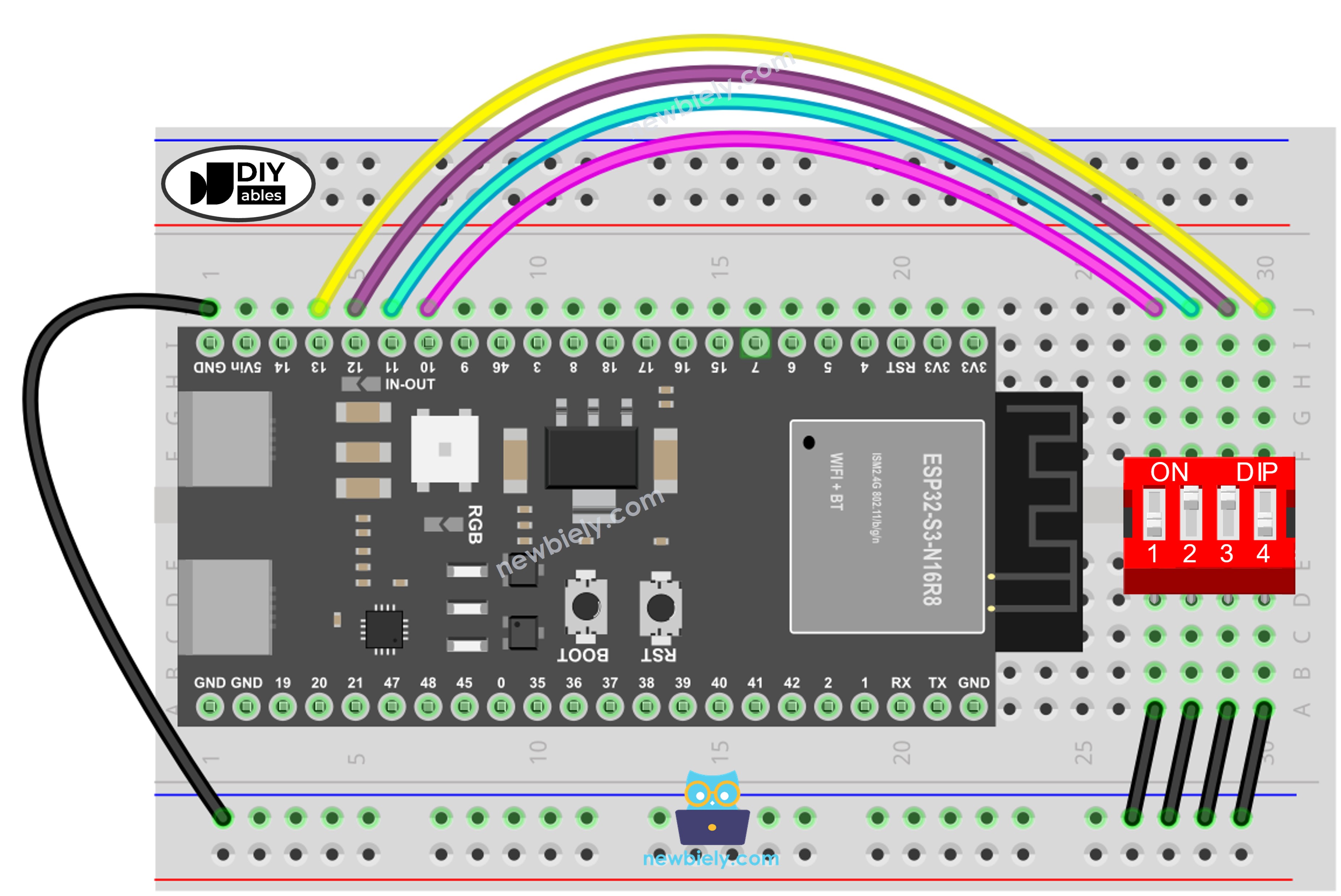
This image is created using Fritzing. Click to enlarge image
ESP32 S3 Code - DIP Switch
The following sections walk through two complementary sketches that demonstrate both ways to use a DIP switch with the ESP32 S3. The first sketch reads each position individually, while the second encodes all positions into a single integer. Both sketches use internal pull-up resistors, so no external resistors are required.
ESP32 S3 Code - Reading the ON/OFF State of the DIP Switch
The following code reads each DIP switch position independently and prints its ON or OFF state to the Serial Monitor. This approach is useful when each position controls a separate feature or setting on your ESP32 S3 project.
Detailed Instructions
- New to ESP32 S3? Complete our Getting Started with ESP32 S3 guide first.
- Do the wiring as shown in the diagram above.
- Connect the ESP32 S3 board to your PC via a USB Type-C cable.
- Open Arduino IDE on your PC.
- Select the right ESP32 S3 board and COM port.
- Click Upload button on Arduino IDE to upload code to ESP32 S3.
- Switch each position on the DIP Switch to ON one by one.
- See the result on Serial Monitor.
- Pro Tip: If you are adapting this for more positions, simply add more pin definitions and loop iterations to match the number of positions on your DIP switch.
ESP32 S3 Code - Encoding the States of DIP Switch into a Number
The following code treats each DIP switch position as a single bit and combines all positions into one integer value. This is ideal for reading configuration codes, device addresses, or multi-bit settings in a single operation on your ESP32 S3.
Detailed Instructions
- New to ESP32 S3? Complete our Getting Started with ESP32 S3 guide first.
- Do the wiring as shown in the diagram above.
- Connect the ESP32 S3 board to your PC via a USB Type-C cable.
- Open Arduino IDE on your PC.
- Select the right ESP32 S3 board and COM port.
- Upload the above code to ESP32 S3.
- Switch each position on the DIP switch to ON one by one.
- See the result on Serial Monitor — it will look like the output below.
- Pro Tip: For a DIP switch with more positions, extend the encoding loop accordingly; the binary-to-decimal mapping scales automatically.
Please note that the encoded value depends on the position of each individual slide switch. The table below shows the complete mapping between ON/OFF positions and the resulting integer for a 4-position DIP switch:
| Position-1 | Position-2 | Position-3 | Position-4 | Binary Value | Decimal Value |
|---|---|---|---|---|---|
| OFF | OFF | OFF | OFF | 0000 | 0 |
| OFF | OFF | OFF | ON | 0001 | 1 |
| OFF | OFF | ON | OFF | 0010 | 2 |
| OFF | OFF | ON | ON | 0011 | 3 |
| OFF | ON | OFF | OFF | 0100 | 4 |
| OFF | ON | OFF | ON | 0101 | 5 |
| OFF | ON | ON | OFF | 0110 | 6 |
| OFF | ON | ON | ON | 0111 | 7 |
| ON | OFF | OFF | OFF | 1000 | 8 |
| ON | OFF | OFF | ON | 1001 | 9 |
| ON | OFF | ON | OFF | 1010 | 10 |
| ON | OFF | ON | ON | 1011 | 11 |
| ON | ON | OFF | OFF | 1100 | 12 |
| ON | ON | OFF | ON | 1101 | 13 |
| ON | ON | ON | OFF | 1110 | 14 |
| ON | ON | ON | ON | 1111 | 15 |
Applications
DIP switches are versatile configuration tools that appear in many practical ESP32 S3 projects and embedded systems. Here are some common applications:
- Device Address Setting: Assign unique I2C or RS485 addresses to multiple identical devices on the same bus without changing firmware.
- Feature Toggling: Enable or disable optional features such as debug output, Wi-Fi mode, or peripheral modules at the hardware level.
- Operation Mode Selection: Switch between different operating modes (e.g., master/slave, standalone/networked) by reading the encoded DIP value at boot.
- Security Code Entry: Use a DIP switch as a simple hardware security mechanism to protect access to a system or enclosure.
- Calibration Offsets: Store fine-tuning offsets or gain settings for sensors that need field adjustment without reprogramming.
Video Tutorial
Watch the step-by-step video walkthrough for this ESP32 S3 project below.
Challenges
Extend your understanding of DIP switches with the ESP32 S3 by taking on these additional exercises. Each challenge builds on the skills from the tutorial and encourages you to explore new use cases.
- Beginner: Modify the read sketch to control a different LED for each DIP switch position — turning the LED on when the position is ON and off when it is OFF.
- Intermediate: Use the encoded integer from the binary sketch to set the I2C address of an OLED display or sensor at runtime, without modifying the source code.
- Advanced: Build a multi-device RS485 network where each node reads its own DIP switch address at startup and only responds to commands addressed to that node.