
ESP32 S3 - LED Matrix
LED matrix displays, also known as dot matrix displays, are widely used in scrolling signs, clocks, and visual indicators. In this tutorial, you will learn how to connect an LED matrix to the ESP32 S3 and display scrolling text, numbers, and animated effects.
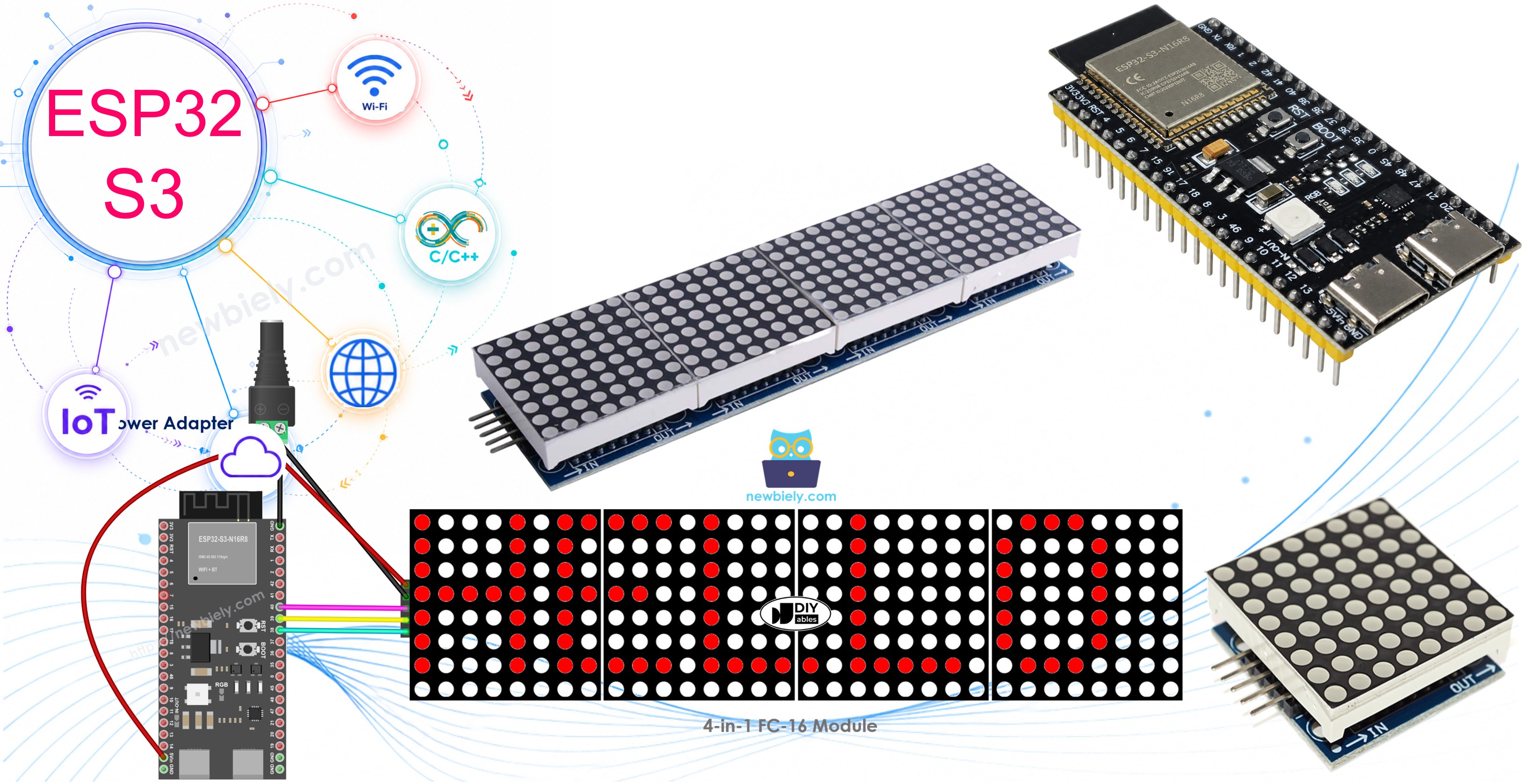
What you'll build:
- Connect an 8x8 or 32x8 LED matrix to the ESP32 S3
- Display static text and numbers on the LED matrix
- Scroll long messages across the LED matrix display
- Apply animated text effects using the MD_Parola library
Hardware Preparation
Or you can buy the following kits:
| 1 | × | DIYables ESP32 S3 Starter Kit (ESP32 S3 included) | |
| 1 | × | DIYables Sensor Kit (18 sensors/displays) |
Additionally, some of these links are for products from our own brand, DIYables .
Overview of LED Matrix
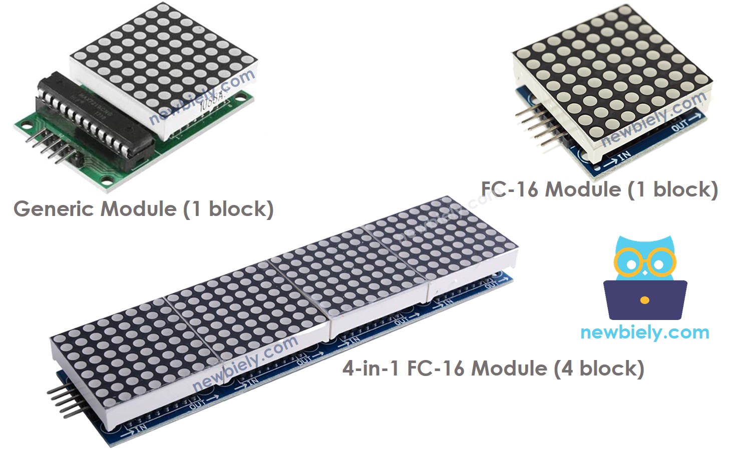
MAX7219-based LED matrices are the most popular choice for use with the ESP32 S3 due to their simple SPI interface and robust library support. Each block in a MAX7219-based LED matrix contains an 8x8 grid of 64 LEDs driven by a single MAX7219 chip, and multiple blocks can be chained together in a daisy-chain configuration to form larger displays such as 16x8 or 32x8. The ESP32 S3 controls the entire chain through just three SPI pins, and you declare the number of blocks in your code.
Key Specifications
- A base unit of an LED matrix is a block
- Each block has an 8x8 LED matrix (64 LED) and a MAX7219 driver
- There are two popular block forms: the generic module and the FC-16 module
- A LED matrix can be composed of a single block or multiple blocks in a daisy-chain
- You can buy a pre-built multiple-block LED Matrix (e.g. 4-in-1, 8-in-1)
- You can also buy multiple blocks and wire them to form a LED matrix with the desired size
- You will declare the size of the LED matrix you use in the ESP32 S3 code
Pinout
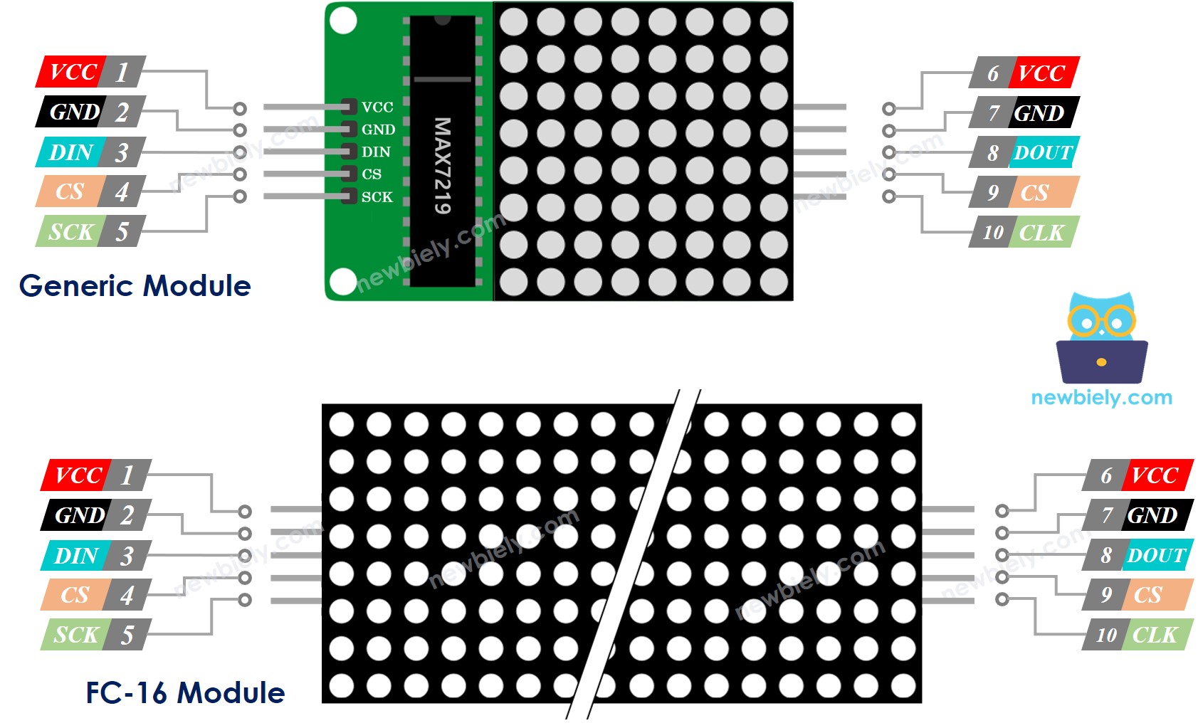
Each LED matrix block exposes two groups of pins — input and output — allowing multiple blocks to be chained together.
- Input pins group:
- VCC: connects to 5V
- GND: connects to GND
- DIN: Data pin, connect to any digital pin of the ESP32 S3
- CS: Chip Select, connect to any digital pin of the ESP32 S3
- CLK: Clock pin, connect to any digital pin of the ESP32 S3
- Output pins group:
- VCC: connects to VCC of the input pins group on the next module
- GND: connects to GND of the input pins group on the next module
- DOUT: Data Out, connects to the DIN pin of the input pins group of the next module
- CS: connects to CS of the input pins group on the next module
- CLK: connects to CLK of the input pins group on the next module
Wiring Diagram
Connect the LED matrix input pins to the ESP32 S3, then chain output pins to the next block's input pins for multi-block displays. If you are using a single block, leave the output pins group unconnected.
Safety Notes
Because the LED matrix display can draw up to 1A at maximum brightness, you should not power it from the 5V pin of the ESP32 S3 alone. Use an external 5V power supply instead, and the ESP32 S3 and LED matrix can share the same 5V power adapter.
The ESP32 S3 connects to the LED matrix via SPI pins:
- GPIO38 (SCK — clock)
- GPIO40 (MOSI — data)
- GPIO39 (CS — chip select, can be changed to any pin)
If the LED matrix is made of a single block:
- Connect the input pins group to ESP32 S3
- Leave the output pins group unconnected
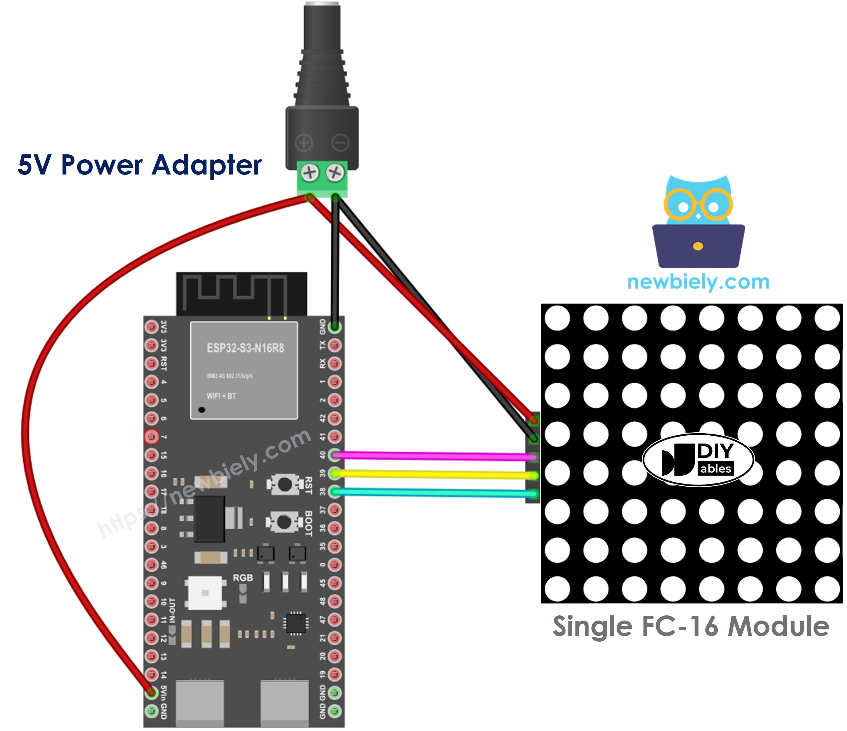
This image is created using Fritzing. Click to enlarge image
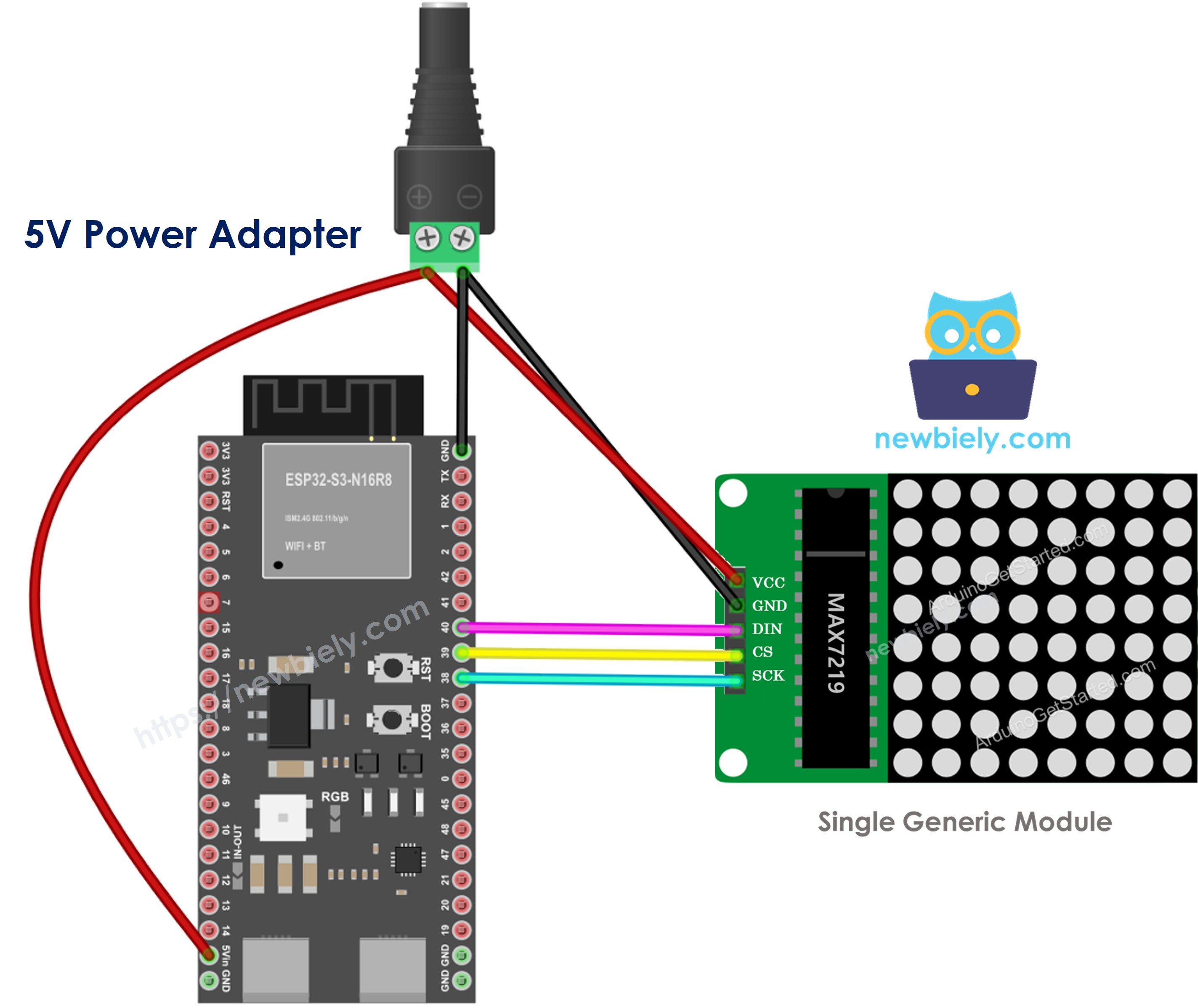
This image is created using Fritzing. Click to enlarge image
If the LED matrix is a pre-built multiple-block unit:
- Connect the input pins group to ESP32 S3
- Leave the output pins group unconnected
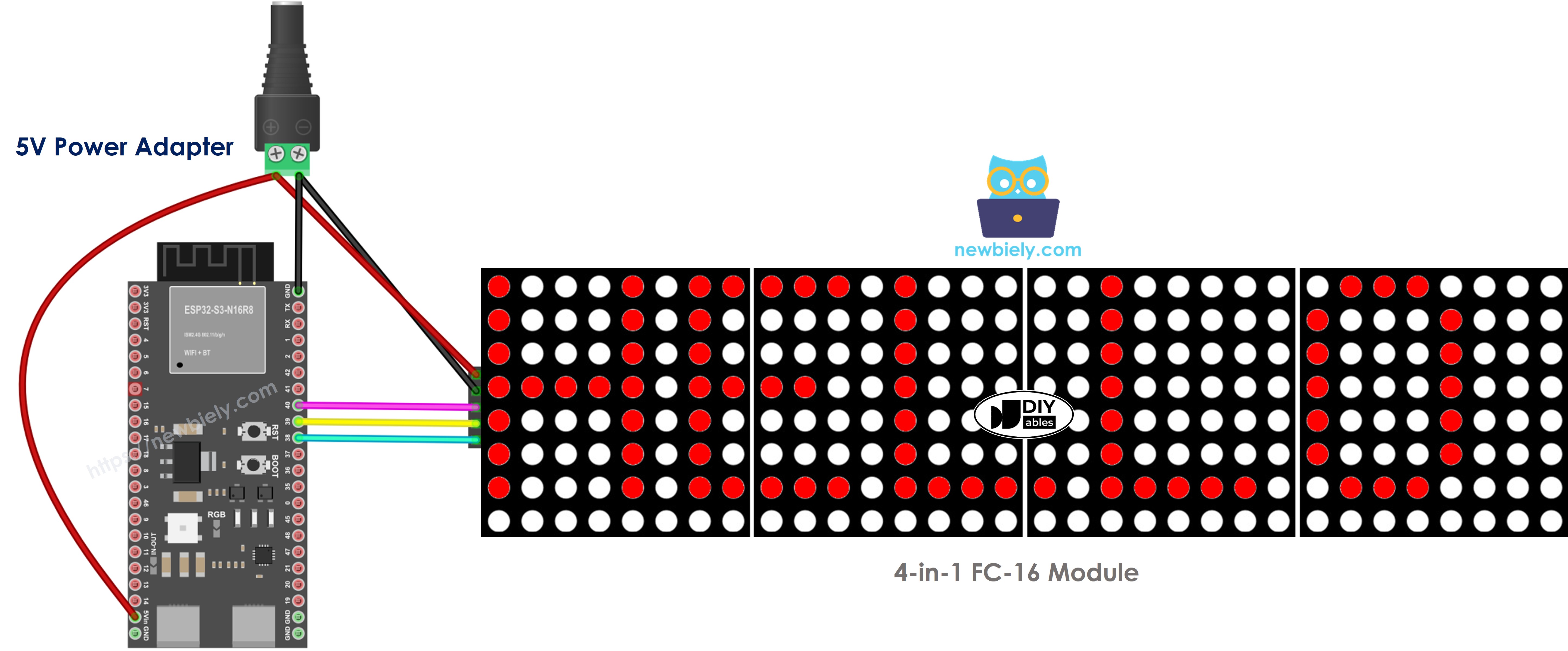
This image is created using Fritzing. Click to enlarge image
If the LED matrix is made of multiple blocks wired by yourself:
- Connect the input pins group of the first block to ESP32 S3
- Connect the output pins group of each block to the input pins group of the next block
- Leave the output pins group of the last block unconnected
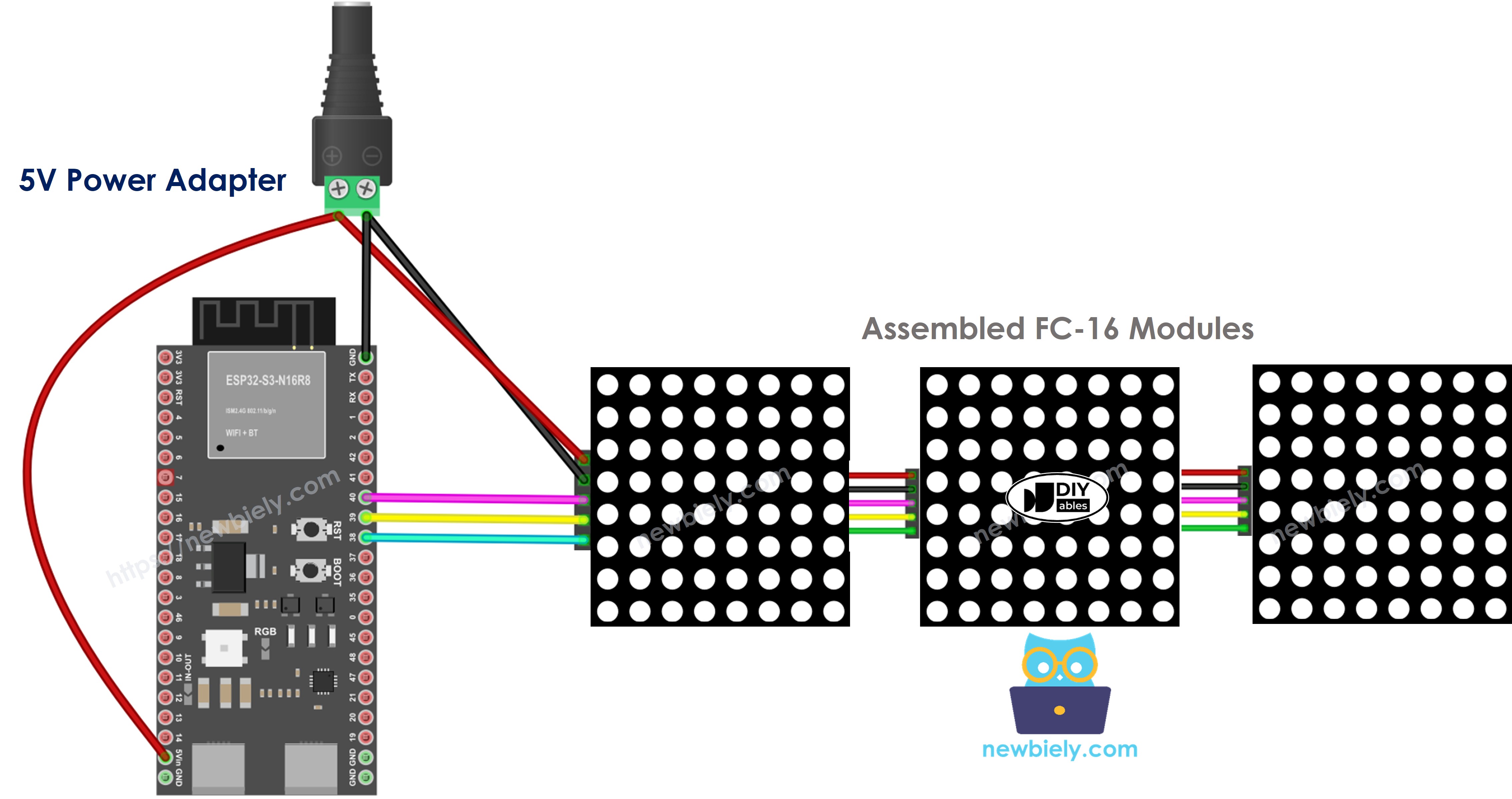
This image is created using Fritzing. Click to enlarge image
How To Program For LED Matrix
Controlling an LED matrix at the register level is complex, but the MD_Parola and MD_MAX72xx libraries make it straightforward by providing high-level functions for text display and animation effects. The following code walkthrough shows each step required to initialize and drive the LED matrix from the ESP32 S3.
- Include libraries:
- Specify which hardware is being used: GENERIC_HW or FC16_HW.
- Define how many LED blocks are used. For example, a 4-in-1 LED matrix has 4 blocks.
- Define the pin that connects to the LED matrix's CS pin. For example, pin GPIO39.
- Create a new instance of the MD_Parola class for the LED matrix display.
- Code in the setup() function:
- Display text, numbers, and animated effects: see the next section.
ESP32 S3 - LED Matrix Code
The following code targets a 32x8 FC-16 LED matrix display with 4 blocks, but you can easily adapt it for 8x8, 16x8, or 64x8 displays by changing the MAX_DEVICES value. Upload the sketch, and you will see text and effects appear on the matrix immediately.
Detailed Instructions
- New to ESP32 S3? Complete our Getting Started with ESP32 S3 guide first.
- Do the wiring as shown in the diagram above.
- Connect the ESP32 S3 board to your PC via a USB Type-C cable.
- Open Arduino IDE on your PC.
- Select the right ESP32 S3 board and COM port.
- Click the Libraries icon on the left bar of the Arduino IDE.
- Search "MD_Parola", then find the MD_Parola library.
- Click Install button.
- Search for MD_Parola created by majicDesigns and click the Install button.
- You will be asked to install the "MD_MAX72XX" library.
- Click Install All button to install the dependency.
- Copy the above code and open it with Arduino IDE.
- Click Upload button on Arduino IDE to upload code to ESP32 S3.
- Observe the LED matrix display showing text and effects.
- Pro Tip: Adjust the setIntensity() value (0–15) to control brightness, and experiment with different PA_EFFECT values in MD_Parola for dozens of built-in animation effects.
ESP32 S3 LED Matrix Code – Scrolling Text
When you want to print a long message that is too long to fit on an LED matrix display, you can use the scroll text effect technique. The following ESP32 S3 code shows how to continuously scroll a message across the LED matrix display from right to left.
For more text effects, please visit MD_Parola Library Reference.
Serial Monitor Output
Open the Serial Monitor at 9600 baud to observe debug messages from the ESP32 S3 as it drives the LED matrix. The following readings show typical output during initialization and display updates:
- [2026-01-15 09:00:01] LED Matrix initialized. Blocks: 4, Intensity: 0
- [2026-01-15 09:00:02] Displaying text: "Hello"
- [2026-01-15 09:00:05] Scroll effect started
- [2026-01-15 09:00:10] Animation complete, restarting loop
Applications
LED matrix displays are versatile output devices used in many real-world projects. Here are some common applications:
- Scrolling Message Board: Display announcements, news tickers, or status messages that scroll continuously.
- Digital Clock: Show time and date with large, readable digits on a multi-block LED matrix.
- Sports Scoreboard: Display live scores and team names in a gymnasium or event venue.
- Queue Management Display: Show queue numbers or ticket status in service counters.
- IoT Dashboard Indicator: Provide a simple visual output for sensor readings or system alerts.
Video Tutorial
Watch the step-by-step video walkthrough for this ESP32 S3 project below.
Challenges
Try these challenges to deepen your understanding of LED matrix control with the ESP32 S3.
- Beginner: Change the displayed text to your name and adjust the brightness using setIntensity() to find a comfortable level for your environment.
- Intermediate: Display the current time on the LED matrix by reading from the ESP32 S3's internal clock or an NTP server over Wi-Fi.
- Advanced: Build a Wi-Fi-connected scrolling message board where you can update the displayed text remotely via a simple web interface hosted on the ESP32 S3.