
ESP32 S3 - Blink multiple LED
This tutorial instructs you how to program the ESP32 S3 to blink multiple LEDs simultaneously without using the delay function. By using the ezLED library and LED arrays, you can cleanly manage multiple LEDs with minimal code.
What you'll build:
- Wire multiple LEDs to the ESP32 S3 board
- Use the ezLED library to blink each LED independently
- Control blink timing without blocking delays
- Simplify the code further using an array of LED objects
Hardware Preparation
Or you can buy the following kits:
| 1 | × | DIYables ESP32 S3 Starter Kit (ESP32 S3 included) | |
| 1 | × | DIYables Sensor Kit (18 sensors/displays) |
Additionally, some of these links are for products from our own brand, DIYables .
Buy Note: Use the LED Module for easier wiring. It includes an integrated resistor.
Overview of LED
The LED (Light Emitting Diode) is one of the most fundamental output components used with microcontrollers like the ESP32 S3. It converts electrical current into visible light and is commonly used for status indicators, debugging signals, and visual feedback in embedded projects. Understanding how to control multiple LEDs independently is an essential skill for building more complex ESP32 S3 applications.
Key Specifications
- Forward voltage: typically 1.8V–3.3V depending on color
- Current limiting resistor: 220 ohm recommended for 3.3V logic
- Control: digital output pin (HIGH = on, LOW = off)
We have a dedicated tutorial about LEDs with detailed information and step-by-step instructions about hardware pinout, working principles, and wiring connections to the ESP32 S3. Learn more at the following link:
Wiring Diagram
Connect each LED in series with a 220 ohm resistor between a GPIO pin on the ESP32 S3 and GND. Make sure to observe correct LED polarity — the longer leg (anode) connects toward the GPIO pin through the resistor, and the shorter leg (cathode) connects to GND.
Safety Notes
Always use a current-limiting resistor with each LED to prevent damage to both the LED and the ESP32 S3 GPIO pin. The ESP32 S3 GPIO pins source up to approximately 40 mA per pin, but keeping current below 12 mA per LED is recommended for safe continuous operation.
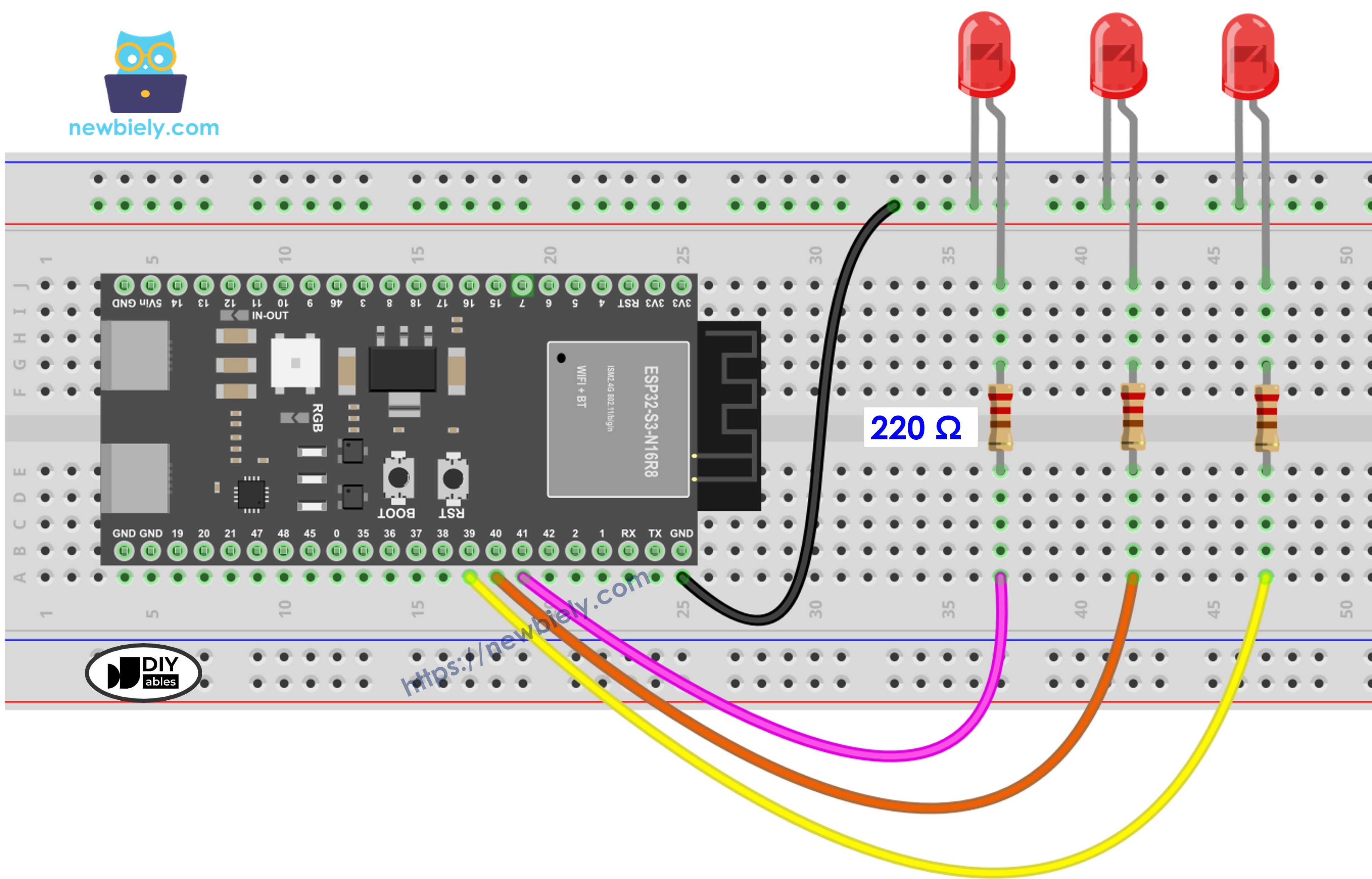
This image is created using Fritzing. Click to enlarge image
| GPIO Pin | LED |
|---|---|
| GPIO 39 | LED 1 (anode via 220Ω resistor) |
| GPIO 40 | LED 2 (anode via 220Ω resistor) |
| GPIO 41 | LED 3 (anode via 220Ω resistor) |
| GND | All LED cathodes |
ESP32 S3 Code - Blink Multiple LEDs
To blink multiple LEDs independently on the ESP32 S3, we cannot use the delay() function because it blocks all other code from running. The following code uses the millis() function along with the ezLED library, which internally manages timestamps so you don't have to handle that complexity yourself. This approach keeps each LED blinking at its own pace without interfering with other operations.
Detailed Instructions
- New to ESP32 S3? Complete our Getting Started with ESP32 S3 guide first.
- Do the wiring as shown in the diagram above.
- Connect the ESP32 S3 board to your PC via a USB Type-C cable.
- Open Arduino IDE on your PC.
- Select the right ESP32 S3 board (e.g. ESP32S3 Dev Module) and COM port.
- Click the Libraries icon on the left bar of the Arduino IDE.
- Search "ezLED", then find the LED library by ArduinoGetStarted.
- Click Install button to install the ezLED library.
- Search for ezLED created by ArduinoGetStarted.com and click the Install button.
- Copy the above code and paste it into Arduino IDE.
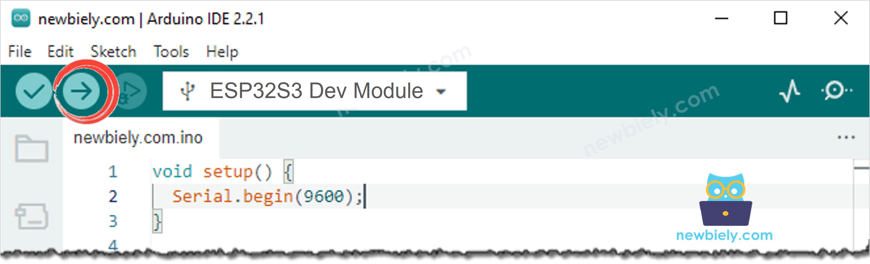
- Compile and upload the code to the ESP32 S3 board by clicking the Upload button on Arduino IDE.
- Check the status of each LED — they should blink independently at their configured intervals.
- Pro Tip: Try adjusting the blink intervals for each LED to create interesting lighting patterns or visual effects.
ESP32 S3 Code - Blink Multiple LEDs Using an Array
We can further optimize the code above by using an array of LED objects. The following code demonstrates how an array makes it easy to scale to any number of LEDs with minimal changes — simply update the pin list and array size. This pattern is especially useful when controlling many LEDs in an ESP32 S3 project.
For more flexible blink patterns and additional control options, refer to the other functions provided by the ezLED library.
Serial Monitor Output
Open the Serial Monitor at 9600 baud to observe runtime messages from the ESP32 S3. The following are example readings you might see during operation:
Applications
Blinking multiple LEDs independently on the ESP32 S3 is a foundational technique that applies to many real-world embedded projects. Here are some practical use cases:
- Status Indicators: Use multiple LEDs to show different system states such as power, connectivity, and error conditions simultaneously.
- Traffic Light Simulation: Implement a simple traffic light controller with red, yellow, and green LEDs cycling at defined intervals.
- Notification System: Flash different LEDs to signal incoming alerts, messages, or sensor events without blocking other program logic.
- Debugging Aid: Assign one LED per subsystem to visually monitor which parts of your ESP32 S3 firmware are active at any moment.
- Decorative Lighting: Create animated LED patterns for displays, costumes, or art installations using independent blink timing.
Video Tutorial
Watch the step-by-step video walkthrough for this ESP32 S3 project below.
Challenges
Practicing with variations of this project will help you deepen your understanding of non-blocking code and LED control on the ESP32 S3. Try the following exercises to extend your skills:
- Beginner: Add a fourth LED on a new GPIO pin and configure it to blink at a different interval than the existing three.
- Intermediate: Modify the array-based code to read blink intervals from an array of values, so you can change all LED timings in one place without touching individual objects.
- Advanced: Use the ESP32 S3's built-in touch pins or a button to toggle each LED's blink state on/off independently at runtime, combining input handling with multi-LED output.