
ESP32 S3 - GPS
The NEO-6M GPS module is a compact and reliable receiver that lets the ESP32 S3 pinpoint its location anywhere on Earth using satellite signals. This tutorial walks you through wiring the module, installing the TinyGPSPlus library, and writing two complete sketches — one for reading GPS coordinates and another for calculating the distance to a predefined location.
What you'll build:
- A GPS data reader that extracts longitude, latitude, altitude, and speed (km/h) using the ESP32 S3 and NEO-6M module
- A sketch that parses NMEA sentences from the GPS module via a hardware serial port on the ESP32 S3
- Real-time GPS data displayed on the Arduino IDE Serial Monitor including date and time
- A second sketch that calculates the distance between the current GPS position and a fixed reference location (London)
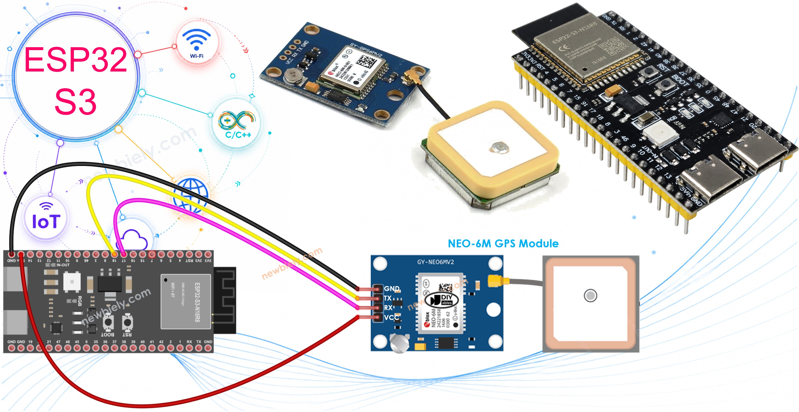
Hardware Preparation
Or you can buy the following kits:
| 1 | × | DIYables ESP32 S3 Starter Kit (ESP32 S3 included) | |
| 1 | × | DIYables Sensor Kit (18 sensors/displays) |
Additionally, some of these links are for products from our own brand, DIYables .
Overview of NEO-6M GPS Module
The NEO-6M is a high-sensitivity GPS receiver module manufactured by u-blox, widely used in hobbyist and maker projects for its compact form factor and straightforward serial interface. It locks onto satellite signals quickly after an initial cold-start period and outputs standard NMEA sentences that are easy to parse in Arduino sketches. The onboard ceramic antenna keeps the component count low while still delivering reliable outdoor performance.
Key Specifications
The NEO-6M GPS module operates at 3.3V–5V and communicates over TTL serial at a default baud rate of 9600 bps. It tracks up to 22 satellites across 50 channels and achieves a horizontal position accuracy of approximately 2.5 m CEP. The module supports GPS, GLONASS (on some variants), and outputs standard NMEA-0183 sentences including GGA, RMC, VTG, and GLL.
Pinout
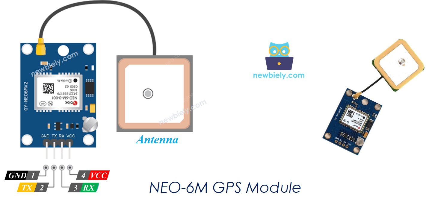
The NEO-6M GPS module has four pins, each with a specific role in powering and communicating with the ESP32 S3:
- VCC — Connect to the 5V power supply
- GND — Connect to ground (0V)
- TX — Transmits NMEA data from the GPS module; connect to a Serial RX pin on the ESP32 S3
- RX — Receives configuration commands; connect to a Serial TX pin on the ESP32 S3
Wiring Diagram between GPS Module and ESP32 S3
Connecting the NEO-6M to the ESP32 S3 requires only four jumper wires and takes just a few minutes on a breadboard. The module needs 5V power, which the ESP32 S3 supplies via its 5V pin when powered over USB, and communicates using UART serial at 3.3V logic levels that the ESP32 S3 accepts directly.
Safety Notes
Always connect the NEO-6M VCC pin to the 5V rail rather than 3.3V to ensure the module's onboard regulator operates correctly and satellite lock is achieved reliably. Place the GPS module near a window or outdoors to give the antenna a clear view of the sky — GPS signals cannot penetrate walls or metal enclosures.
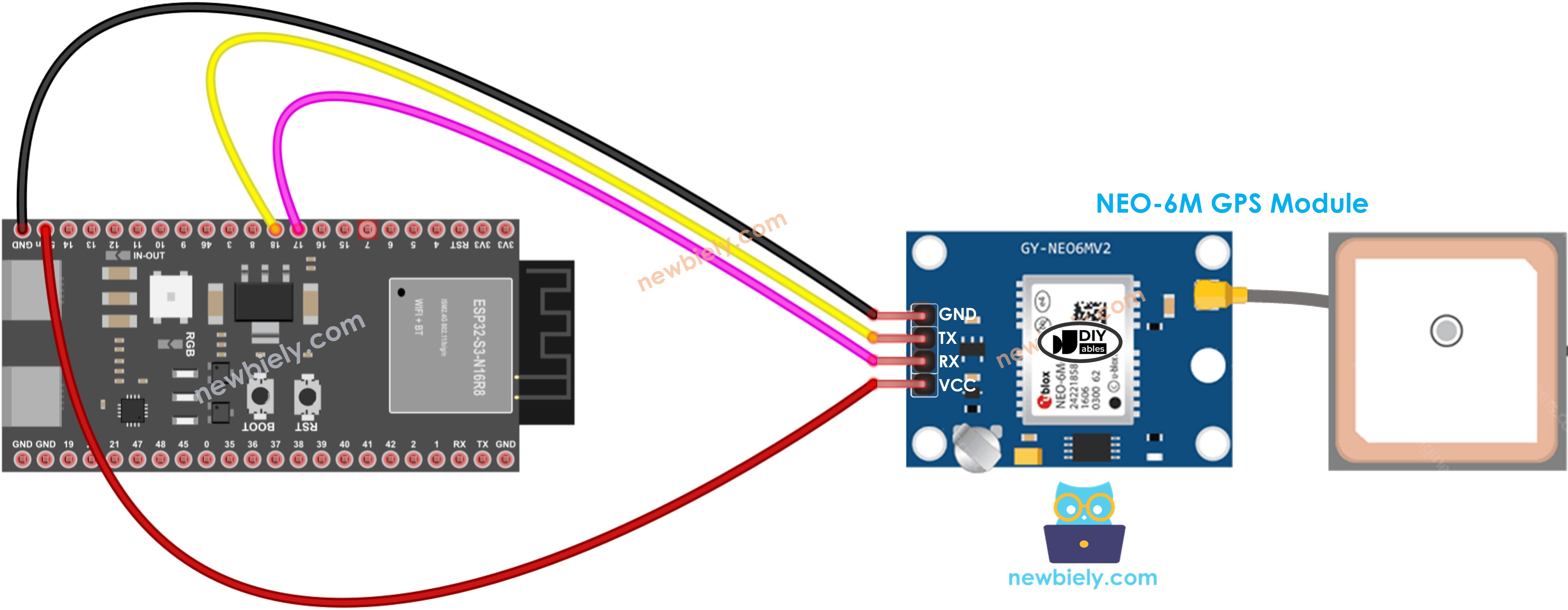
This image is created using Fritzing. Click to enlarge image
| GPS Module Pin | ESP32 S3 Pin |
|---|---|
| VCC | 5V |
| GND | GND |
| TX | RX1 (GPIO18) |
| RX | TX1 (GPIO17) |
ESP32 S3 Code
Reading GPS Coordinates, Speed (km/h), and Date Time
The following sketch uses the TinyGPSPlus library to parse the serial stream from the NEO-6M GPS module and extract longitude, latitude, altitude, speed, and UTC date-time values. It initializes a second hardware serial port on the ESP32 S3 dedicated to GPS communication, leaving the primary serial port free for the Arduino IDE Serial Monitor output.
Detailed Instructions
- New to ESP32 S3? Complete our Getting Started with ESP32 S3 guide first.
- Do the wiring as shown in the diagram above.
- Connect the ESP32 S3 board to your PC using a USB Type-C cable.
- Open the Arduino IDE on your PC.
- In the Arduino IDE, select the correct board (ESP32S3 Dev Module or equivalent) and COM port under Tools.
- On Arduino IDE, go to Manage Libraries in the left bar.
- Search "TinyGPSPlus", then find the TinyGPSPlus library by Mikal Hart.
- Click Install to install the TinyGPSPlus library.
- Search for TinyGPSPlus created by Mikal Hart and click the Install button.
- Copy the sketch above and open it in the Arduino IDE.
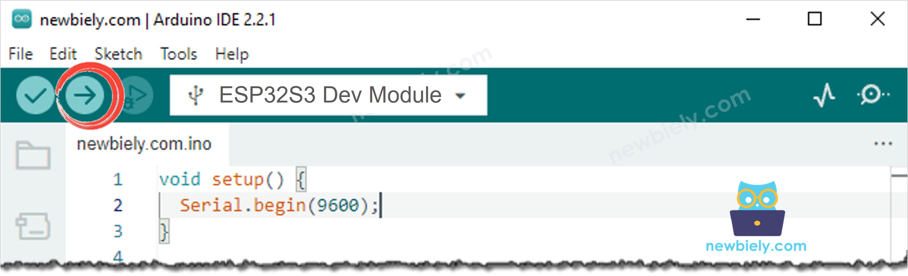
- Click the Upload button to compile and flash the sketch to the ESP32 S3.
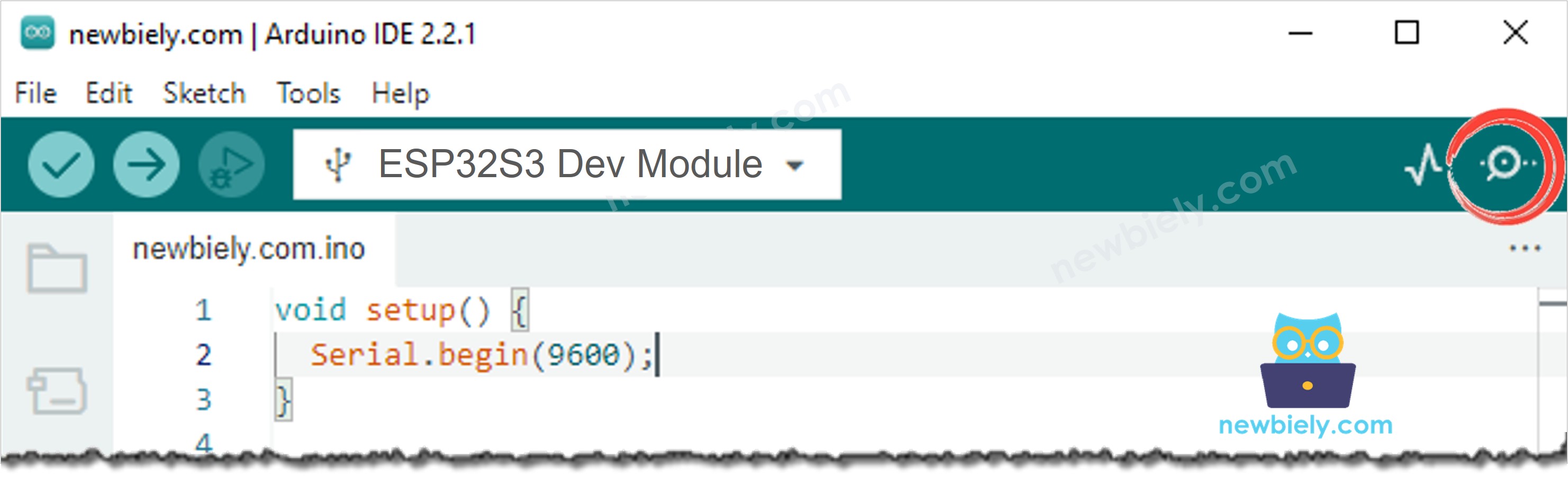
- Once the upload is complete, open the Serial Monitor from the Tools menu or the monitor icon.
- Set the baud rate to 115200 in the Serial Monitor dropdown.
- Take the ESP32 S3 and GPS module near a window or outdoors and watch the readings appear once a satellite fix is acquired.
- Pro Tip: The NEO-6M can take 30–90 seconds for its first satellite lock (cold start). Subsequent power-ups with a saved almanac lock much faster — leave the module powered while you iterate on your code.
Line-by-line Code Explanation
The above ESP32 S3 code contains line-by-line explanation. Please read the comments in the code!
Serial Monitor Output
When the NEO-6M GPS module connected to the ESP32 S3 acquires a satellite fix, the Serial Monitor will display readings similar to the following:
ESP32 S3 Code
Calculating the Distance from Current Location to a Predefined Location
The following sketch extends the GPS reader by calculating the distance between the current GPS coordinates and a fixed reference point — in this case, the coordinates of London (lat: 51.508131, long: -0.128002). The TinyGPSPlus library's built-in distanceBetween() function handles the haversine calculation, so no external math library is needed.
Detailed Instructions
- Copy the sketch above and open it in the Arduino IDE.
- Click the Upload button to compile and flash the sketch to the ESP32 S3.
- Open the Serial Monitor and set the baud rate to 115200.
- Once a GPS fix is acquired, the Serial Monitor will display the distance to London in both meters and kilometers.
- Pro Tip: Replace the London coordinates in the sketch with the latitude and longitude of any location you choose — your home, a waypoint, or a project deployment site — to adapt this example to your own use case.
Line-by-line Code Explanation
The above ESP32 S3 code contains line-by-line explanation. Please read the comments in the code!
Serial Monitor Output
When the GPS module acquires a fix and the distance sketch is running on the ESP32 S3, the Serial Monitor will display output similar to the following:
Application and Project Ideas
The ESP32 S3 paired with the NEO-6M GPS module enables a broad range of location-aware applications in IoT, robotics, and outdoor electronics. Here are some directions worth exploring:
- Asset tracker: Build a portable GPS tracker that logs coordinates to an SD card or sends them over Wi-Fi for real-time location monitoring.
- Geofence alarm: Trigger an alert or notification when the device moves outside a predefined geographic boundary.
- Navigation aid: Display turn-by-turn distance and bearing to a waypoint on an OLED or LCD screen.
- Speed logger: Record speed data during a drive or ride and upload logs to a server for later analysis.
- Autonomous vehicle guidance: Use GPS waypoints to guide a rover or drone along a predefined outdoor route.
- Weather station with location tagging: Attach GPS coordinates and timestamps to environmental sensor readings for geo-referenced data.
- Search and rescue beacon: Build a low-power device that periodically transmits its GPS position over Wi-Fi or LoRa from the ESP32 S3.
Video Tutorial
Watch the step-by-step video walkthrough for this ESP32 S3 project below.
Challenge Yourself
Once you have the basic GPS readings working on your ESP32 S3, there are plenty of ways to deepen your understanding and extend the project. Try the challenges below in order of difficulty:
- Beginner: Modify the sketch to display GPS coordinates with six decimal places for higher precision output.
- Beginner: Add an LED that blinks once when a valid satellite fix is first acquired.
- Intermediate: Display live latitude, longitude, speed, and altitude on an OLED screen instead of the Serial Monitor.
- Intermediate: Log GPS readings with timestamps to a micro SD card every 10 seconds to create a simple GPS track recorder.
- Advanced: Implement a multi-waypoint navigation system that calculates bearing and distance to each waypoint in sequence and advances to the next when within 5 meters.
- Advanced: Build a geofence system that sends a Wi-Fi alert via HTTP POST when the ESP32 S3 moves outside a defined radius around a home coordinate.