Arduino Nano ESP32 - Motion Sensor
This tutorial provides instructions on how to use Arduino Nano ESP32 with HC-SR501 motion sensor. In detail, we will learn:
- How an HC-SR501 motion sensor works
- How to connect an HC-SR501 motion sensor to Arduino Nano ESP32
- How to read the value from an HC-SR501 motion sensor to detect the human
Hardware Preparation
Or you can buy the following kits:
| 1 | × | DIYables Sensor Kit (18 sensors/displays) |
Additionally, some of these links are for products from our own brand, DIYables .
Overview of HC-SR501 Motion Sensor
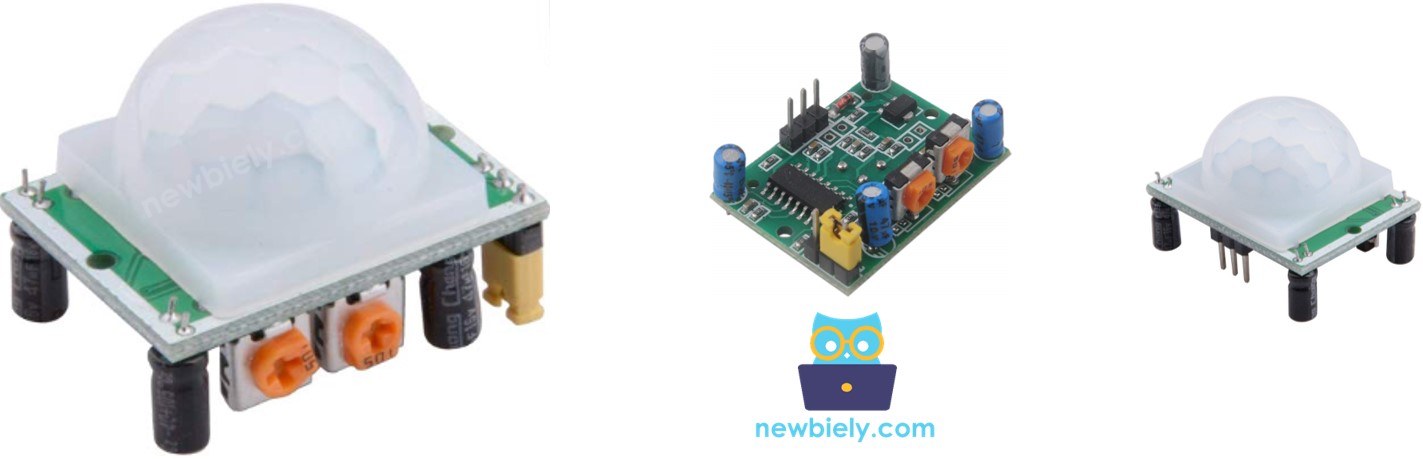
HC-SR501 PIR sensor is a sensor that can detect the movement of humans (or animals). It's widely used to detect the presence of humans in many applications (automatically turning ON/OFF light bulb, activating/deactivating escalator, detecting an intruder, opening/closing the door...)
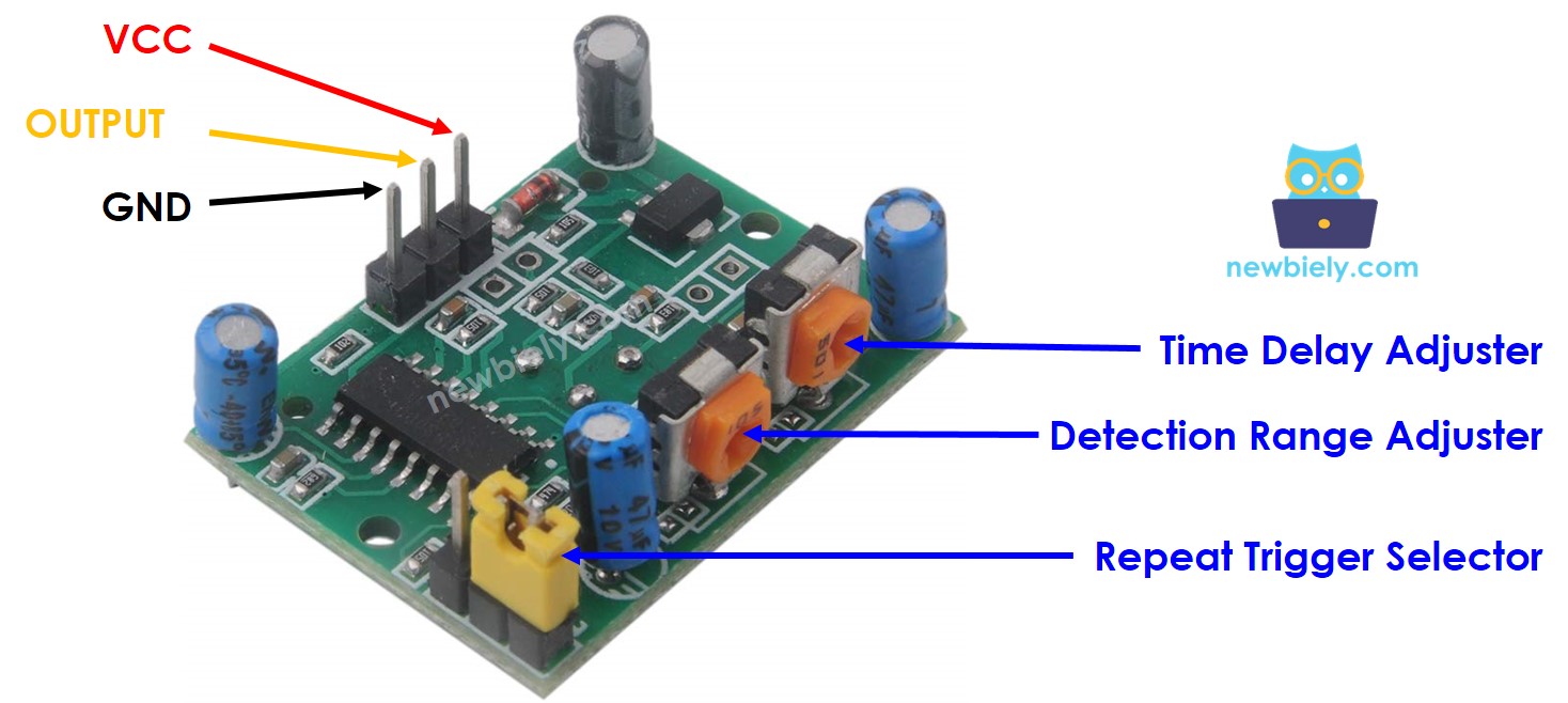
HC-SR501 Motion Sensor Pinout
The HC-SR501 motion sensor has 3 pins:
- VCC pin: connect this pin to VCC (5V)
- GND pin: connect this pin to GND (0V)
- OUTPUT pin: connect this pin to ESP32's input pin. This pin outputs the signal corresponds to the motion deltection:
- LOW if no motion is detected
- HIGH if motion is detected.
- The object is emitting the infrared way.
- The object is moving or shaking
- If an object is emitting the infrared ray but NOT moving (e.g, a person stands still without moving), it is NOT detected by the sensor.
- If an object is moving but NOT emitting the infrared ray (e.g, robot or vehicle), it is NOT detected by the sensor.
- If the movement is detected, the humans are present
- If the movement is NOT detected, the humans are NOT present
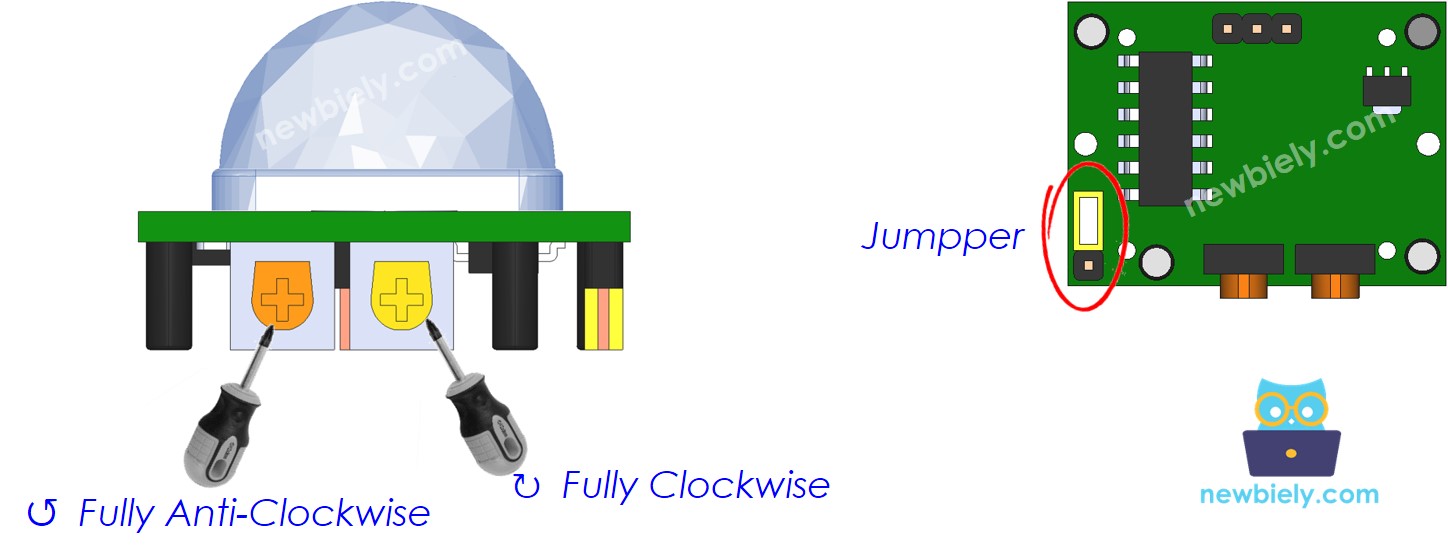
There are also two potentiometers and one jumper on the HC-SR501 motion sensor. These potentiometers and jupperare used to adjust the sensor's setting. The detailed instruction is described in the Advanced Uses.
How HC-SR501 Motion Sensor Works
The working principle of HC-SR501 sensor is based on the change of the infrared radiation on the moving object. To be detected by the HC-SR501 sensor, the object must meet two requirements:
So:
The animals and humans emit infrared ray naturally. Therefore, the animals and humans can be delected by the HC-SR501 sensor if they is moving. .
The above video shows the working principle of the motion sensor. In practice, the motion sensor can works differently according to the sensor setting (described in the Advanced Uses section)
Detecting the Presence of Human
The sensor itself does NOT directly detect the presence of humans, the sensor just detects the movement. And then the presence of humans is infered on movement detection:
There is an issue with this rule in pracice, the humans are present in sensor range but NOT moving. The the movement is NOT detected. The Arduino Nano ESP32 (or MCU) deduces that human is NOT present.
However, The sensor's widely used to detect the human in many applications because this issue is NOT serious and the sensor's price is cheap.
Arduino Nano ESP32 and HC-SR501 Motion Sensor
When an ESP32's pin is configured as a digital input, It can read the state (LOW or HIGH) of anything it is connected to.
By connecting the ESP32's pin to the OUTPUT pin of the HC-SR501 sensor, we can use the Arduino Nano ESP32 code to read the value of the OUTPUT pin, and then infer the motion.
Wiring Diagram between HC-SR501 Motion Sensor and Arduino Nano ESP32
- The wiring diagram when powering the Arduino Nano ESP32 board via USB port.
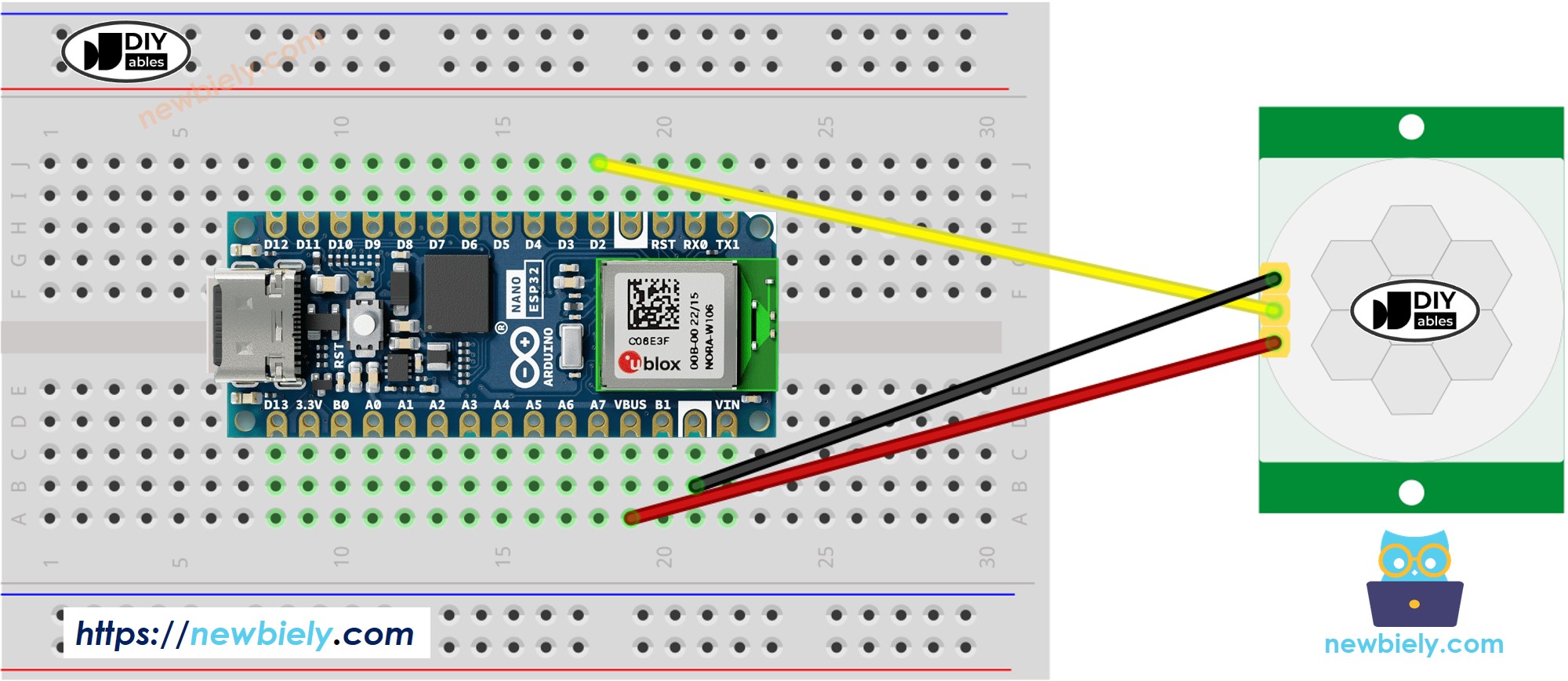
This image is created using Fritzing. Click to enlarge image
- The wiring diagram when powering the Arduino Nano ESP32 board via Vin pin.
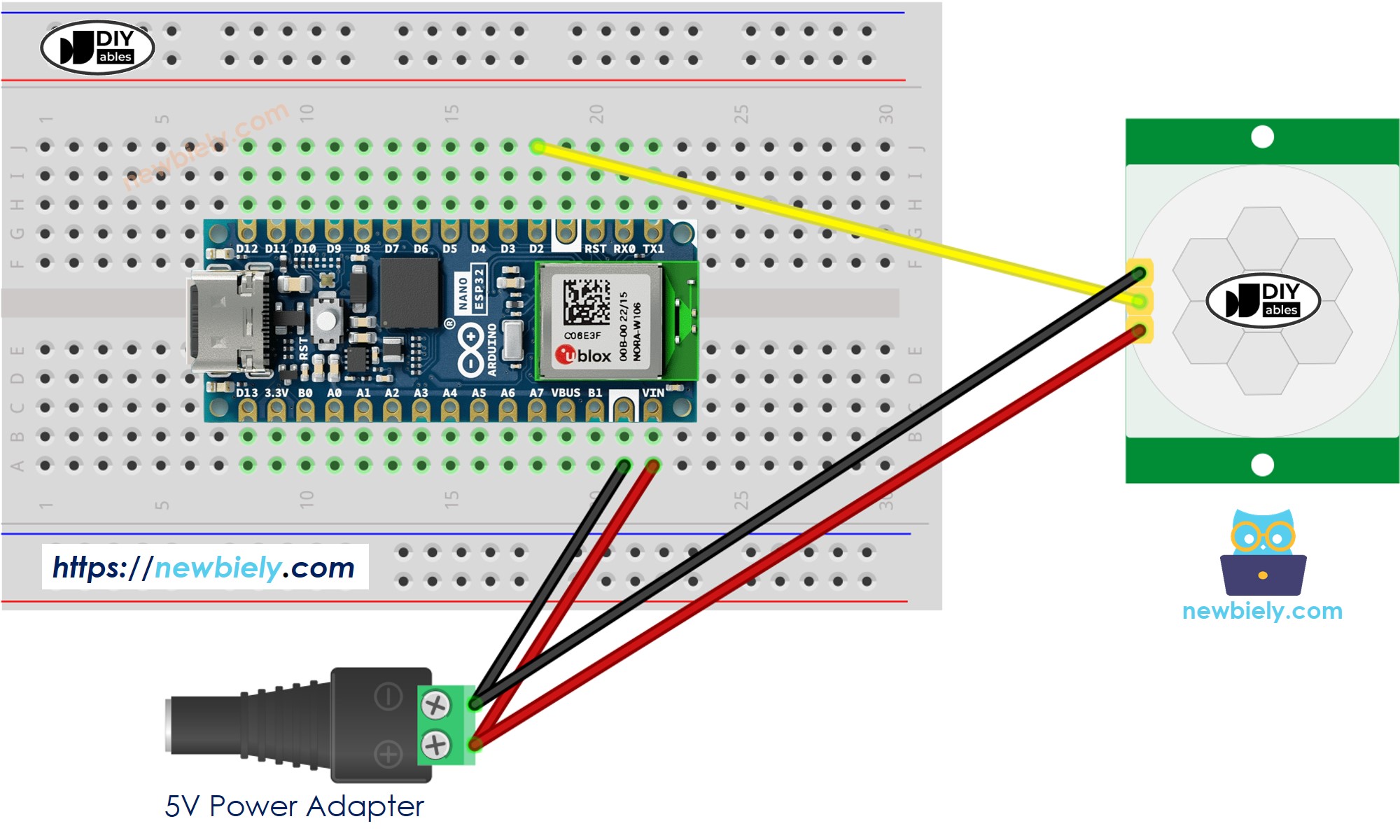
This image is created using Fritzing. Click to enlarge image
Initial Setting
| Detection Range Adjuster | Fully screw it in the clockwise direction. |
| Time Delay Adjuster | Fully screw it in the anti-clockwise direction. |
| Repeat Trigger Selector | Put jumper like the below image. |
How To Program Motion Sensor
- Configure an ESP32's pin to the digital input mode by using pinMode() function
- Read the state of sensor's OUTPUT pin by using digitalRead() function.
- Detect motion start (pin's state change from LOW to HIGH)
- Detect motion stop (pin's state change from HIGH to LOW)
Arduino Nano ESP32 Code
Detailed Instructions
- If this is the first time you use Arduino Nano ESP32, see how to setup environment for Arduino Nano ESP32 on Arduino IDE.
- Copy the above code and paste it to Arduino IDE.
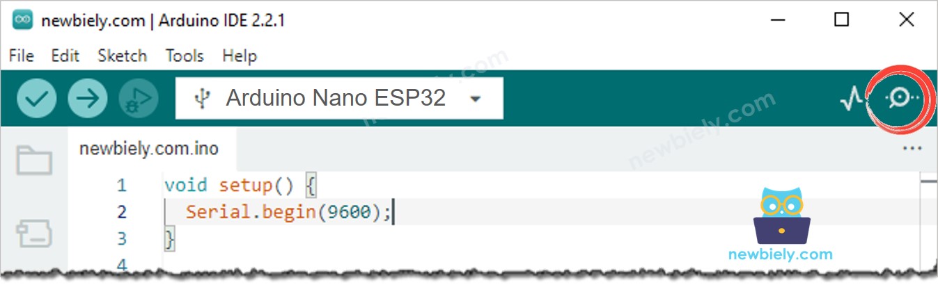
- Compile and upload code to Arduino Nano ESP32 board by clicking Upload button on Arduino IDE
- Open Serial Monitor on Arduino IDE
- Move your hand in front of sensor range
- See the output in Serial Monitor