Arduino Nano ESP32 - DC Motor
This tutorial provides instructions on how to use Arduino Nano ESP32 to control DC motor using L298N Motor Driver. In detail, We will learn how to control the speed and direction of DC motor. We will learn how to control a single DC motor, and then two DC motors using a single L298N motor driver.
Hardware Preparation
Or you can buy the following kits:
| 1 | × | DIYables Sensor Kit (18 sensors/displays) |
Additionally, some of these links are for products from our own brand, DIYables .
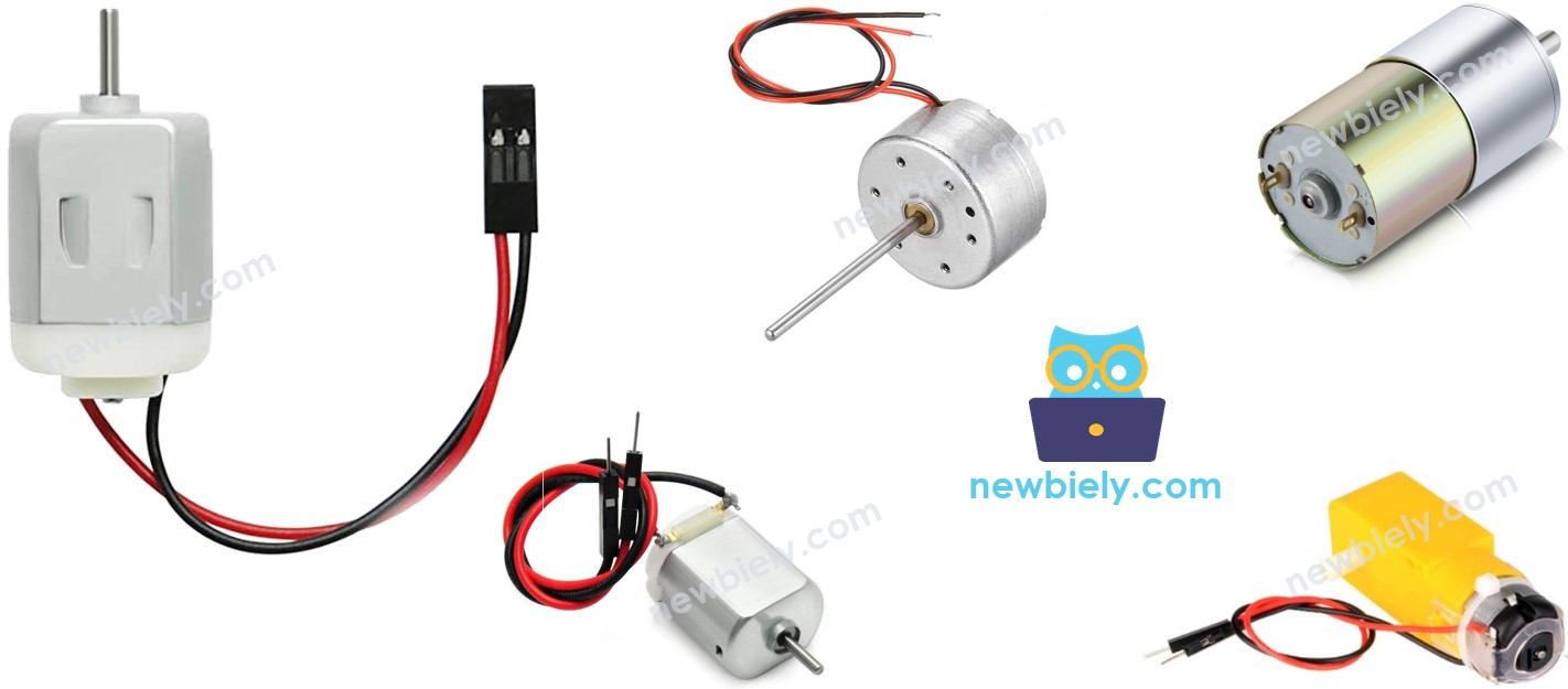
Overview of DC Motor
DC Motor Pinout
A DC Motor includes two wires: Negative(black), and Positive(red)
How DC Motor Works
The direction and speed of DC motor will be determined by how we provide power to it. The below images how the detaied relation between power and speed/direction
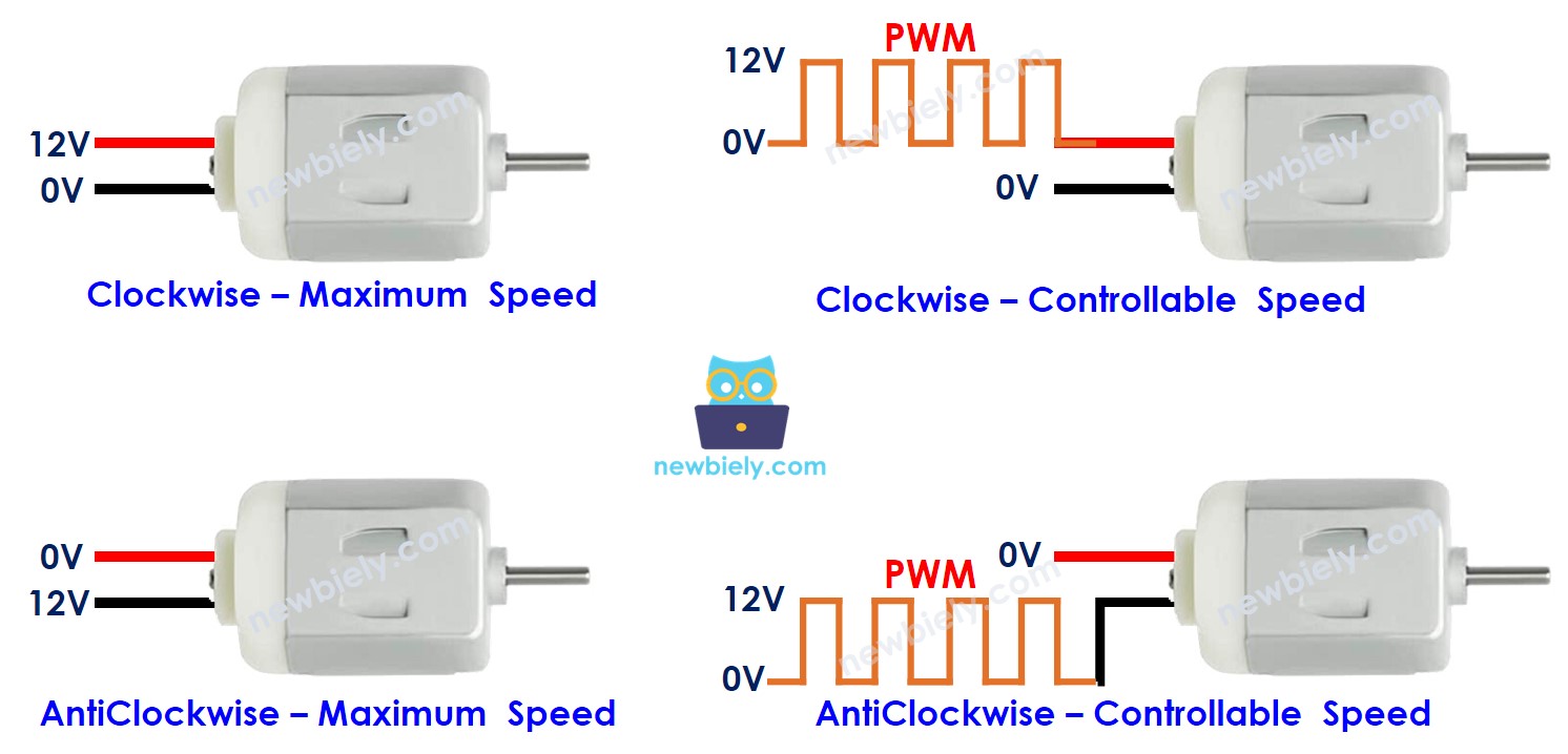
In the case of using PWM, there bigger duty cycle The PWM is, the bigger speed the montor spins.
The following animation shows how a PWM signal is used to control the speed of a DC motor:
How to control speed and direction of DC motor using Arduino Nano ESP32
Firstly, The DC motor works with high voltage that can burn Arduino Nano ESP32 ⇒ We cannot connects DC motor directly to Arduino Nano ESP32. We need a hardware driver between DC motor and Arduino Nano ESP32. The driver takes three responsibilities:
- Protecting Arduino Nano ESP32 from the high voltage
- Receiving the signal from Arduino Nano ESP32 to change the pole of power supply to control the motor's direction.
- Amplifying the PWM signal from Arduino Nano ESP32 (current and voltage) to control the motor's speed
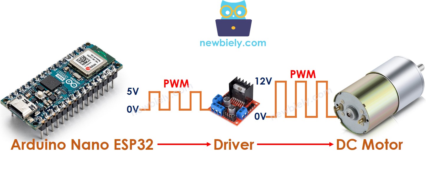
There are a lot of DC motor drivers. This tutorial will use the L298N driver.
Overview of L298N Driver
A single L298N driver can control two DC motors or a stepper motor. This tutorial uses this driver to control the DC motor.
L298N Driver Pinout
The below image shows the L298N driver's pinout.
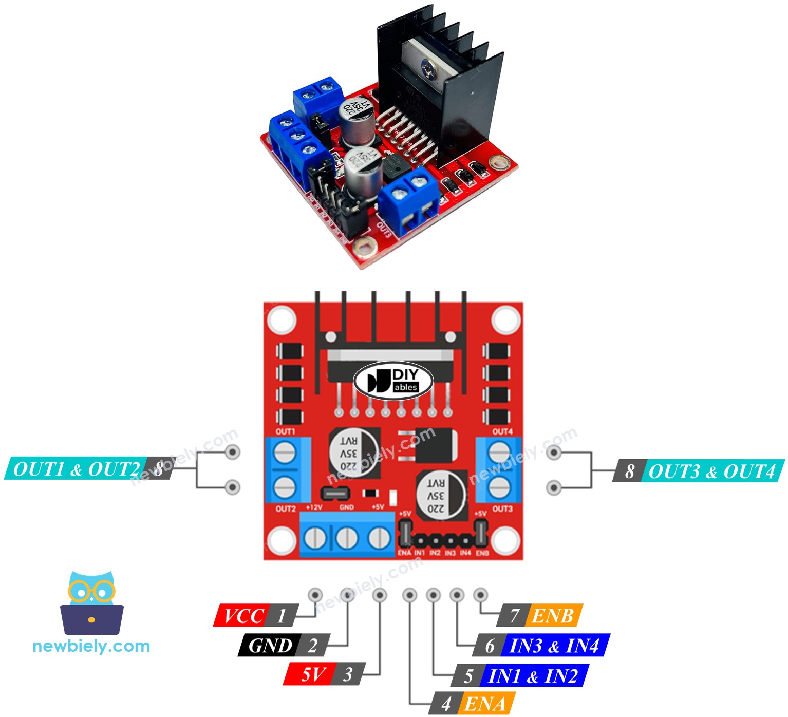
The detailed explanation for each pin is avaialble in this Arduino - DC motor tutorial
A single L298N driver can control two DC motor independently:
- The first motor (called motor A) is controlled by IN1, IN2, ENA, OUT1, OUT2 pins.
- The second motor (called motor B) is controlled by IN3, IN4, ENB, OUT3, OUT4 pins.
How To Control the Speed of DC Motor via L298N Driver
It is simple to control the speed of the DC motor by generating a PWM signal to the ENA/ENB pin of L298N. We can do this by:
- Connecting an ESP32's digital output pin to L298N's ENA/ENB pin
- Creating a PWM signal to the ENA/ENB pin by using analogWrite() function. This PWM signal goes though L298N Driver and amplified current and voltage before going to to the DC motor
The speed is a value between 0 and 255. If it is 255, the motor runs at maximum speed. If it is 0, the motor stops.
How To Control the Direction of DC Motor via L298N Driver
The DC motor A's direction can be controlled by IN1 and IN2 pins. The following table shows the rekation between the motor's direction and signal on IN1 and IN2 pins.
| IN1 pin | IN2 pin | Direction |
|---|---|---|
| HIGH | LOW | DC Motor A rotates in clockwise direction |
| LOW | HIGH | DC Motor A rotates in anticlockwise direction |
| HIGH | HIGH | DC Motor A stops |
| LOW | LOW | DC Motor A stops |
Similarly, The below table is for DC motor B
| IN3 pin | IN4 pin | Direction |
|---|---|---|
| HIGH | LOW | DC Motor B rotates in clockwise direction |
| LOW | HIGH | DC Motor B rotates in anticlockwise direction |
| HIGH | HIGH | DC Motor B stops |
| LOW | LOW | DC Motor B stops |
Let's learn how to program to control it. Let's take the motor A for example. The motor B is similar.
- Controling the motor A dirrection to clockwise
- Controlingthe motor A dirrection to anti-clockwise
※ NOTE THAT:
The DC motor's direction is opposite if the wiring between DC motor and L298N driver is in reverse order. In that case, swap OUT1 and OUT2 pins.
How To Stop DC Motor
There are two ways to stop a DC motor
- Controlling the speed to 0
- Controlling IN1 IN2 pins to the same LOW or HIGH
- Or
How to control a DC motor using L298N driver.
Wiring Diagram
There are three jumpers on the L298N module. Remove all of them before doing the wiring.
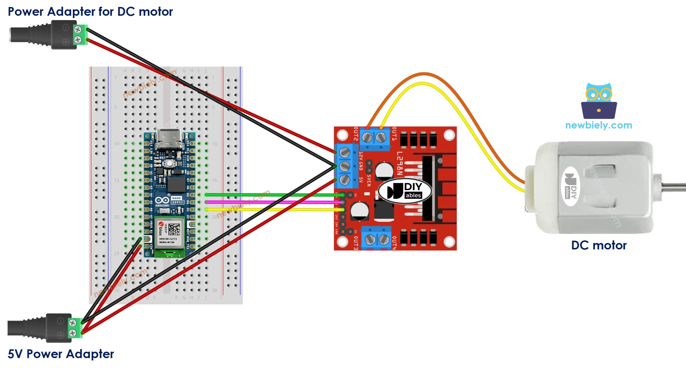
This image is created using Fritzing. Click to enlarge image
Arduino Nano ESP32 Code
Let's see the below code that does the foloowing thing one by one:
- Arduino Nano ESP32 controls the DC motor's speed increasingly.
- Arduino Nano ESP32 inverts the DC motor's direction
- Arduino Nano ESP32 controls the DC motor's speed decreasingly.
- Arduino Nano ESP32 stops the DC motor
Detailed Instructions
- If this is the first time you use Arduino Nano ESP32, see how to setup environment for Arduino Nano ESP32 on Arduino IDE.
- Remove all three jumpers on the L298N module.
- Copy the above code and paste it to Arduino IDE.
- Compile and upload code to Arduino Nano ESP32 board by clicking Upload button on Arduino IDE
- Watch the DC motor, You will see:
- DC motor is accelerated and spins at the maximum speed during 2 second
- DC motor's direction is reversed
- DC motor spins in the reverse direction at the maximum speed during 2 seconds
- DC motor is decelerated
- DC motor stop 2 second
- The above process is repeated infinitely.
※ NOTE THAT:
This tutorial provides instructions on how to control the DC motor speed relatively. To control the absolute speed (round per second), it needs to use a PID controller and the feedback from an encoder.
How to Control two DC Motors using L298N Driver
(coming soon)