Arduino Nano ESP32 - Potentiometer LED
This tutorial instructs you how to use Arduino Nano ESP32 with the potentiometer to change the brightness of LED.
Hardware Preparation
Or you can buy the following kits:
| 1 | × | DIYables Sensor Kit (18 sensors/displays) |
Disclosure: Some of the links provided in this section are Amazon affiliate links. We may receive a commission for any purchases made through these links at no additional cost to you.
Additionally, some of these links are for products from our own brand, DIYables .
Additionally, some of these links are for products from our own brand, DIYables .
Buy Note: Use the LED Module for easier wiring. It includes an integrated resistor.
Overview of LED and Potentiometer
We have specific tutorials about LED and potentiometer. Each tutorial contains detailed information and step-by-step instructions about hardware pinout, working principle, wiring connection to ESP32, Arduino Nano ESP32 code... Learn more about them at the following links:
Wiring Diagram
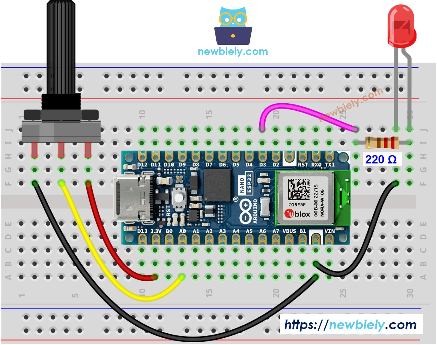
This image is created using Fritzing. Click to enlarge image
How To Program
- Reads the input on analog pin (value between 0 and 4095)
int analogValue = analogRead(36); // GPIO36 (ADC0)
- Scales it to brightness (value between 0 and 255)
int brightness = map(analogValue, 0, 4095, 0, 255);
- Sets the brightness LED
analogWrite(LED_PIN, brightness);
Arduino Nano ESP32 Code
/*
* This Arduino Nano ESP32 code was developed by newbiely.com
*
* This Arduino Nano ESP32 code is made available for public use without any restriction
*
* For comprehensive instructions and wiring diagrams, please visit:
* https://newbiely.com/tutorials/arduino-nano-esp32/arduino-nano-esp32-potentiometer-led
*/
#define POTENTIOMETER_PIN A0 // The Arduino Nano ESP32 pin connected to Potentiometer pin
#define LED_PIN D3 // The Arduino Nano ESP32 pin connected to LED's pin
// the setup routine runs once when you press reset:
void setup() {
// initialize serial communication at 9600 bits per second:
Serial.begin(9600);
// set the ADC attenuation to 11 dB (up to ~3.3V input)
analogSetAttenuation(ADC_11db);
// declare LED pin to be an output:
pinMode(LED_PIN, OUTPUT);
}
// the loop routine runs over and over again forever:
void loop() {
// reads the input on analog pin A0 (value between 0 and 4095)
int analogValue = analogRead(POTENTIOMETER_PIN);
// scales it to brightness (value between 0 and 255)
int brightness = map(analogValue, 0, 4095, 0, 255);
// sets the brightness LED that connects to pin 3
analogWrite(LED_PIN, brightness);
// print out the value
Serial.print("Analog value = ");
Serial.print(analogValue);
Serial.print(" => brightness = ");
Serial.println(brightness);
delay(100);
}
Detailed Instructions
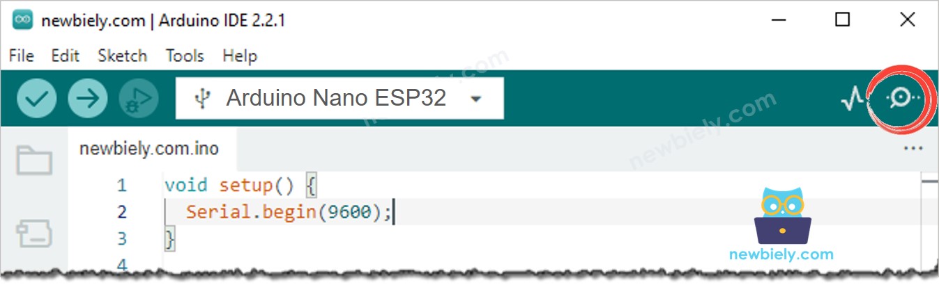
- If this is the first time you use Arduino Nano ESP32, see how to setup environment for Arduino Nano ESP32 on Arduino IDE.
- Copy the above code and paste it to Arduino IDE.
- Compile and upload code to Arduino Nano ESP32 board by clicking Upload button on Arduino IDE
- Open Serial Monitor on Arduino IDE
- Rotate the potentiometer
- See the LED fading
- See the result on Serial Monitor. It looks like the below:
8
Serial.println("Hello World!");
Message (Enter to send message to 'Arduino Nano ESP32' on 'COM15')
New Line
9600 baud
Analog value = 6 => brightness = 1
Analog value = 34 => brightness = 8
Analog value = 89 => brightness = 22
Analog value = 149 => brightness = 37
Analog value = 214 => brightness = 53
Analog value = 297 => brightness = 74
Analog value = 365 => brightness = 90
Analog value = 431 => brightness = 107
Analog value = 510 => brightness = 127
Analog value = 589 => brightness = 146
Analog value = 695 => brightness = 173
Analog value = 790 => brightness = 196
Analog value = 970 => brightness = 241
Analog value = 996 => brightness = 248
Analog value = 1018 => brightness = 253
Analog value = 4095 => brightness = 255