Arduino Nano ESP32 - RFID
This tutorial provides instructions on how to use Arduino Nano ESP32 with RC522 RFID/NFC reader to read the information from RFID/NFC tag.
Hardware Preparation
Or you can buy the following kits:
| 1 | × | DIYables Sensor Kit (18 sensors/displays) |
Disclosure: Some of the links provided in this section are Amazon affiliate links. We may receive a commission for any purchases made through these links at no additional cost to you.
Additionally, some of these links are for products from our own brand, DIYables .
Additionally, some of these links are for products from our own brand, DIYables .
Overview of RFID-RC522 Module
Pinout
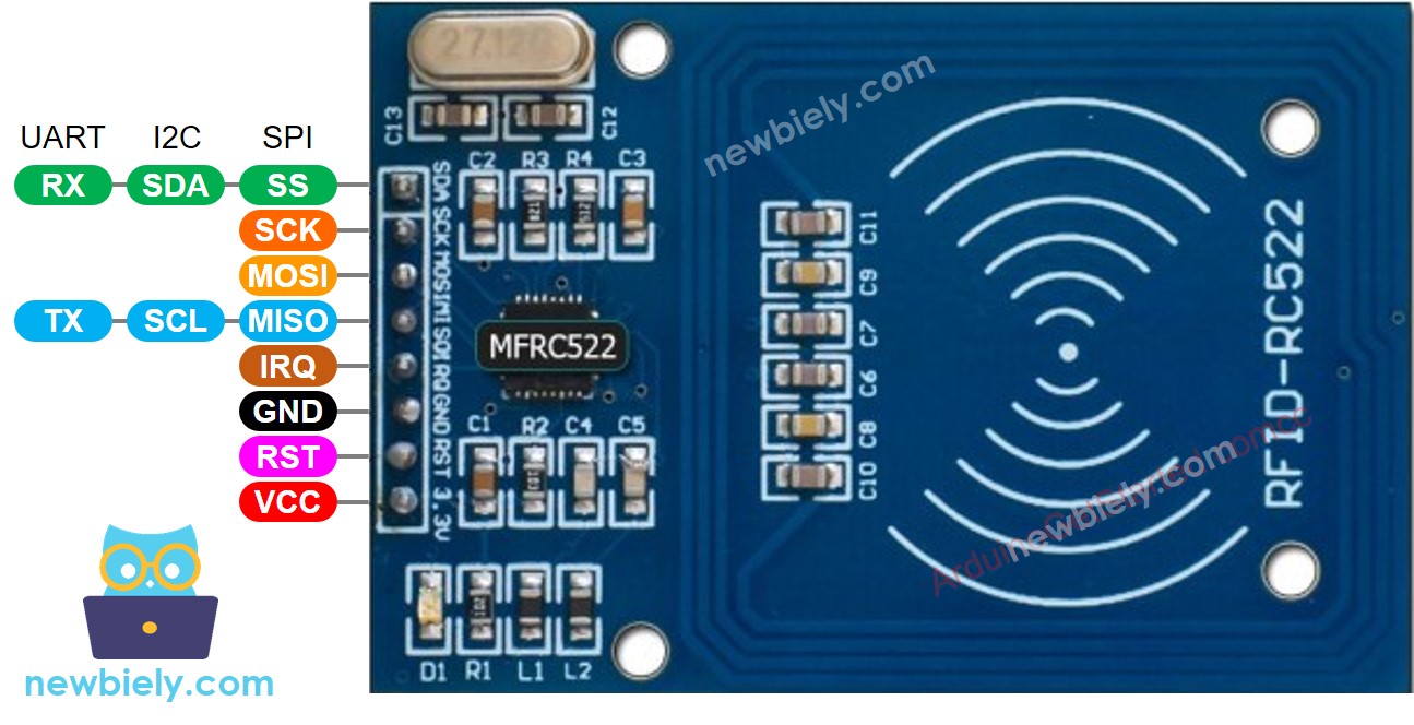
The RFID-RC522 module has 8 pins, some pins are shared among three communication interfaces: SPI, I2C, UART. At a time, only one communication mode can be used. The pin are:
- GND pin: connect this pin to GND (0V)
- VCC pin: connect this pin to VCC (3.3)
- RST pin: is a pin for reset and power-down. When this pin goes low, hard power-down is enabled. On the rising edge, the module is reset.
- IRQ pin: is an interrupt pin that can alert the Arduino Nano ESP32 when RFID tag comes into its detection range.
- MISO/SCL/TX pin: works as:
- MISO pin if SPI interface is enabled
- SCL pin if I2C interface is enabled
- TX pin if UART interface is enabled.
- MOSI pin: works as MOSI if SPI interface is enabled.
- SCK pin: works as SCK if SPI interface is enabled
- SS/SDA/RX pin: works as:
- SS pin if SPI interface is enabled
- SDA pin when I2C interface is enabled
- RX pin when UART interface is enabled.
- The pins order can vary according to manufacturers. ALWAYS use the labels printed on the module. The above image shows the pinout of the modules from DIYables manufacturer.
- The RFID-RC522 module works with 3.3V. Do not connect the RFID-RC522 module's VCC pin to 5V. 5V can burn the RFID-RC522 module.
- This tutorial uses SPI interface for communication between Arduino Nano ESP32 and RFID-RC522 module.
※ NOTE THAT:
Wiring Diagram
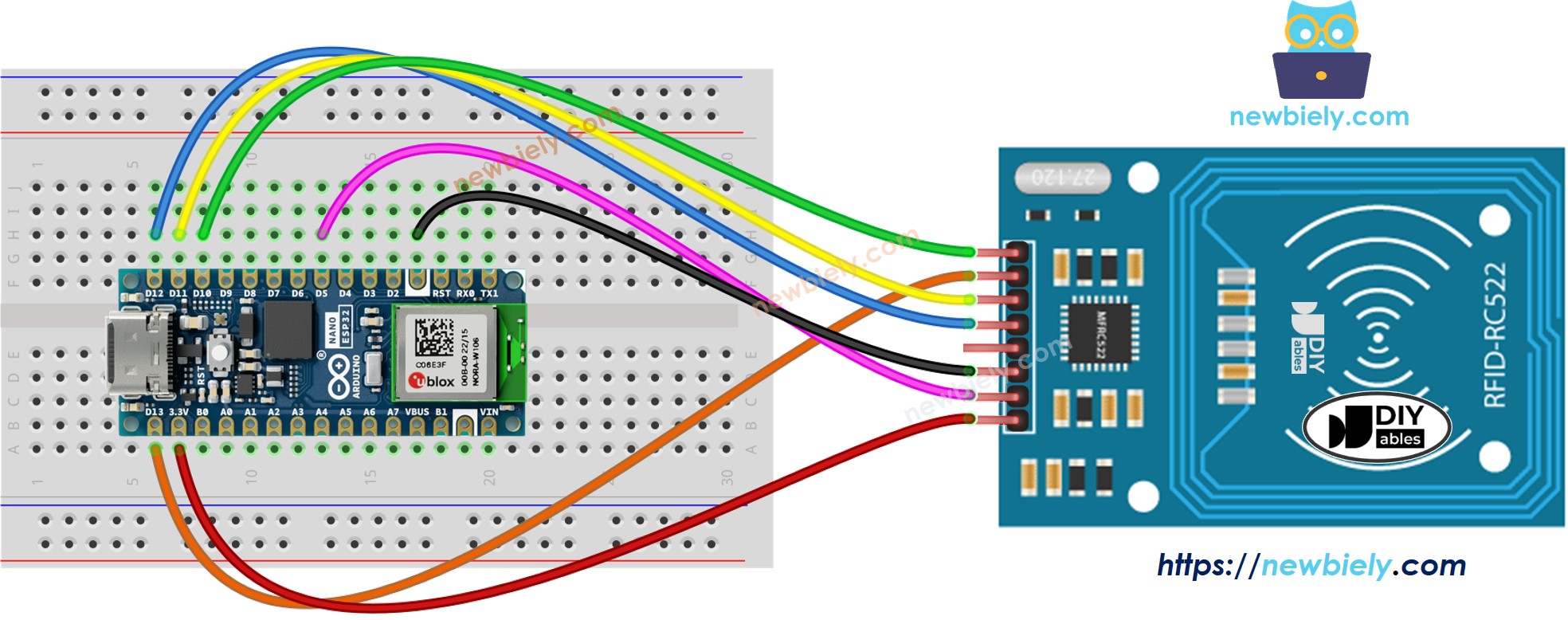
This image is created using Fritzing. Click to enlarge image
The wiring table between RFID/NFC RC522 Module and Arduino Nano ESP32
| RFID/NFC RC522 | Arduino Nano ESP32 |
|---|---|
| SS | → D10 |
| SCK | → D13 |
| MOSI | → D11 |
| MISO | → D12 |
| IRQ | not connected |
| GND | → GND |
| RST | → D5 |
| VCC | → 3.3V |
Arduino Nano ESP32 RFID/NFC Code
/*
* This Arduino Nano ESP32 code was developed by newbiely.com
*
* This Arduino Nano ESP32 code is made available for public use without any restriction
*
* For comprehensive instructions and wiring diagrams, please visit:
* https://newbiely.com/tutorials/arduino-nano-esp32/arduino-nano-esp32-rfid
*/
#include <SPI.h>
#include <MFRC522.h>
#define SS_PIN D10 // Arduino Nano ESP32 pin connected to RC522's SS pin
#define RST_PIN D5 // Arduino Nano ESP32 pin connected to RC522's RST pin
MFRC522 rfid(SS_PIN, RST_PIN);
void setup() {
Serial.begin(9600);
SPI.begin(); // init SPI bus
rfid.PCD_Init(); // init MFRC522
Serial.println("Tap an RFID/NFC tag on the RFID-RC522 reader");
}
void loop() {
if (rfid.PICC_IsNewCardPresent()) { // new tag is available
if (rfid.PICC_ReadCardSerial()) { // NUID has been readed
MFRC522::PICC_Type piccType = rfid.PICC_GetType(rfid.uid.sak);
Serial.print("RFID/NFC Tag Type: ");
Serial.println(rfid.PICC_GetTypeName(piccType));
// print UID in Serial Monitor in the hex format
Serial.print("UID:");
for (int i = 0; i < rfid.uid.size; i++) {
Serial.print(rfid.uid.uidByte[i] < 0x10 ? " 0" : " ");
Serial.print(rfid.uid.uidByte[i], HEX);
}
Serial.println();
rfid.PICC_HaltA(); // halt PICC
rfid.PCD_StopCrypto1(); // stop encryption on PCD
}
}
}
Detailed Instructions
- If this is the first time you use Arduino Nano ESP32, see how to setup environment for Arduino Nano ESP32 on Arduino IDE.
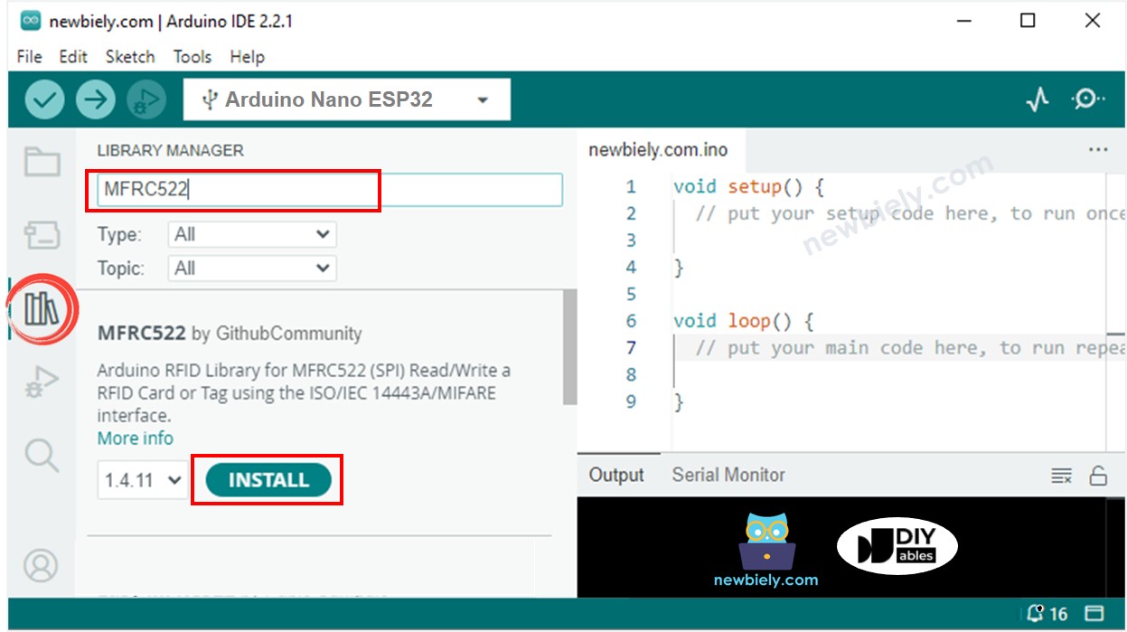
- Open the Library Manager by clicking on the Library Manager icon on the left navigation bar of Arduino IDE
- Type “MFRC522” on the search box, then look for the library by GithubCommunity
- Install the library by clicking on Install button.
- Copy the above code and paste it to Arduino IDE.
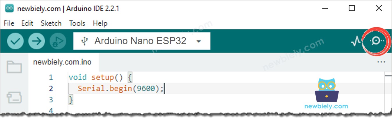
- Compile and upload code to Arduino Nano ESP32 board by clicking Upload button on Arduino IDE
- Open Serial Monitor on Arduino IDE
- Tap several RFID/NFC tags on RFID-RC522 module
- See the UID printed on Serial Monitor
8
Serial.println("Hello World!");
Message (Enter to send message to 'Arduino Nano ESP32' on 'COM15')
New Line
9600 baud
Tap an RFID/NFC tag on the RFID-RC522 reader
RFID/NFC tag Type: MIFARE 1KB
UID: 2B B8 59 B1
RFID/NFC tag Type: MIFARE Ultralight or Ultralight C
UID: 15 75 46 7A 2C 5B 7E