Arduino Nano ESP32 - Ultrasonic Sensor - LED
This tutorial instructs you how to use Arduino Nano ESP32 and Ultrasonic sensor to control the LED. In detail:
- The Arduino Nano ESP32 automatically turns LED on when an object is close to the ultrasonic sensor.
- The Arduino Nano ESP32 automatically turns LED off when an object is far from the ultrasonic sensor.
Hardware Preparation
Or you can buy the following kits:
| 1 | × | DIYables Sensor Kit (18 sensors/displays) |
Additionally, some of these links are for products from our own brand, DIYables .
Buy Note: Use the LED Module for easier wiring. It includes an integrated resistor.
Overview of LED and Ultrasonic Sensor
We have specific tutorials about LED and ultrasonic sensor. Each tutorial contains detailed information and step-by-step instructions about hardware pinout, working principle, wiring connection to ESP32, Arduino Nano ESP32 code... Learn more about them at the following links:
Wiring Diagram
The wiring diagram with power supply from USB cable
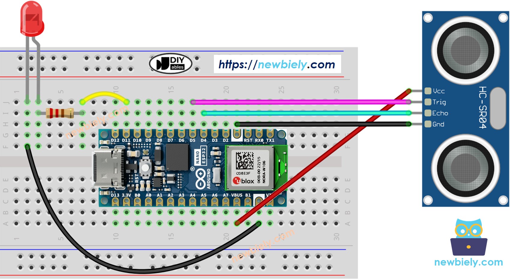
This image is created using Fritzing. Click to enlarge image
The wiring diagram with power supply from 5v adapter
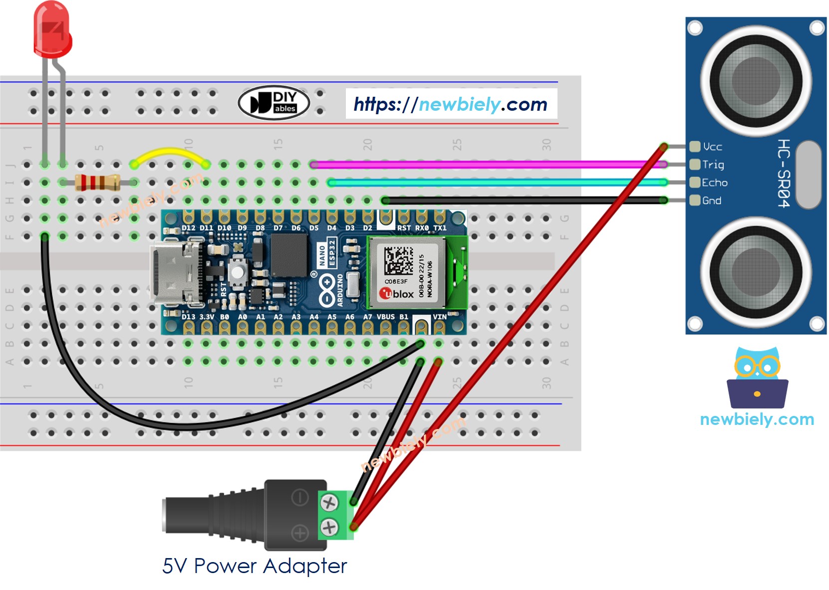
This image is created using Fritzing. Click to enlarge image
Arduino Nano ESP32 Code
Detailed Instructions
To get started with Arduino Nano ESP32, follow these steps:
- If you are new to Arduino Nano ESP32, refer to the tutorial on how to set up the environment for Arduino Nano ESP32 in the Arduino IDE.
- Wire the components according to the provided diagram.
- Connect the Arduino Nano ESP32 board to your computer using a USB cable.
- Launch the Arduino IDE on your computer.
- Select the Arduino Nano ESP32 board and its corresponding COM port.* Copy the above code and paste it to Arduino IDE.
- Compile and upload code to Arduino Nano ESP32 board by clicking Upload button on Arduino IDE
- Move your hand in front of sensor
- See the change of LED's state
Line-by-line Code Explanation
The above Arduino Nano ESP32 code contains line-by-line explanation. Please read the comments in the code!