Arduino Nano ESP32 - Light Sensor
This tutorial provides instructions on how to use Arduino Nano ESP32 with the light sensor. In detail, we will learn:
- How light sensor works.
- How to connect light sensor to Arduino Nano ESP32.
- How to program for Arduino Nano ESP32 to read value from a light sensor.
Hardware Preparation
Or you can buy the following kits:
| 1 | × | DIYables Sensor Kit (18 sensors/displays) |
Additionally, some of these links are for products from our own brand, DIYables .
The LDR light sensor is very affordable, but it requires a resistor for wiring, which can make the setup more complex. To simplify the wiring, you can use an LDR light sensor module as an alternative.
Overview of Light Sensor
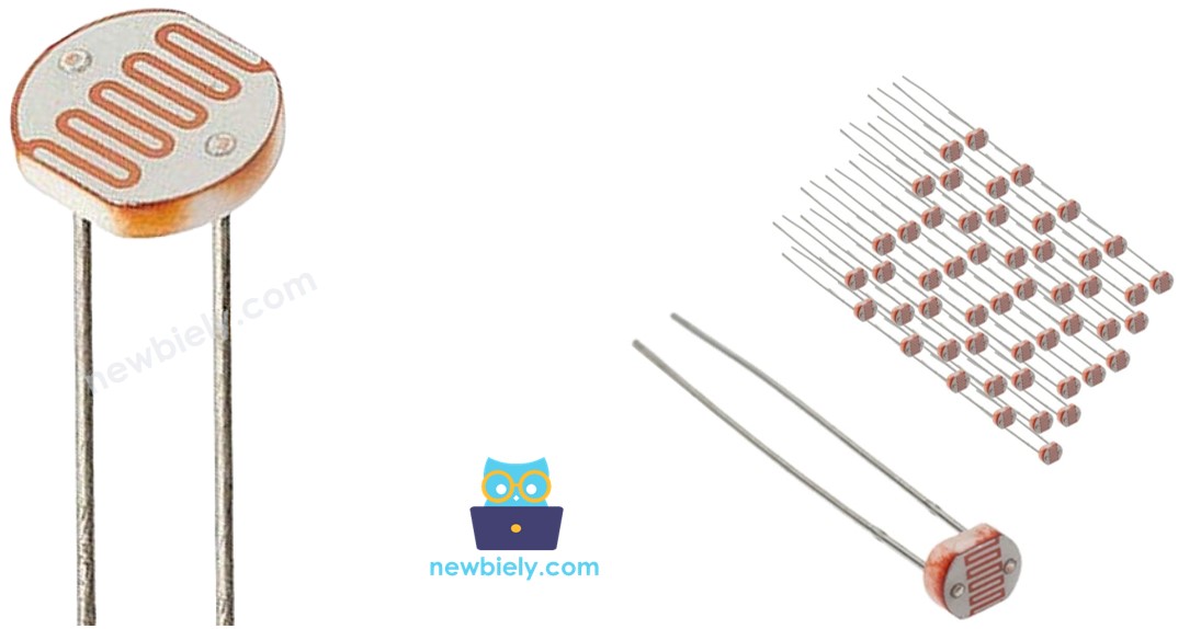
The most wide-used light sensor is a photoresistor (also known as photocell, or light-dependent resistor, LDR).
It can be used to detect the presence ofthe light. It can also be used to measure the illuminance/brightness level of the light.
Light Sensor Pinout
A light sensor has two pins. Just like a normal resistor, We do NOT need to distinguish these pins.
How Light Sensor Works
The photoresistor's resistance is in inverse proportion to the intensity of the light. The less light the photoresistor's face is exposed, the more the photoresistor's resistance is. Therefore, we can infer how bright the ambient light is by measuring the photoresistor's resistance.
WARNING
The value measured by photoresistor reflects the approximated tendency of the light's intensity, it does NOT represent exactly the luminous flux. Therefore, the photoresistor should not be used in an application that requires high accuracy. calibration is also required for some kind application.
Arduino Nano ESP32 - Light Sensor
The ESP32's analog input pin converts the voltage (between 0v and ADC_VREF - default is 3.3V) into integer values (between 0 and 4095), called analog value or ADC value. By connecting an analog input pin of Arduino Nano ESP32 to the photoresistor, we can read the analog value by using analogRead() function.
Wiring Diagram between Light Sensor and Arduino Nano ESP32
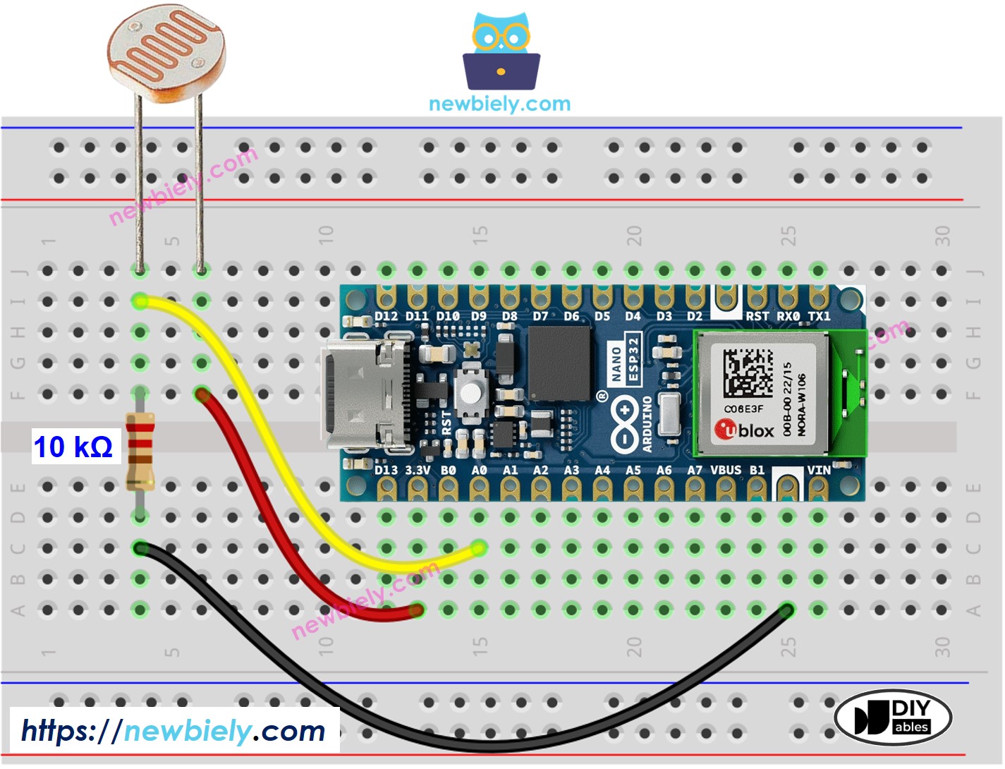
This image is created using Fritzing. Click to enlarge image
Arduino Nano ESP32 Code
The below Arduino Nano ESP32 code reads the value from a light sensor and infers the light level
Detailed Instructions
- If this is the first time you use Arduino Nano ESP32, see how to setup environment for Arduino Nano ESP32 on Arduino IDE.
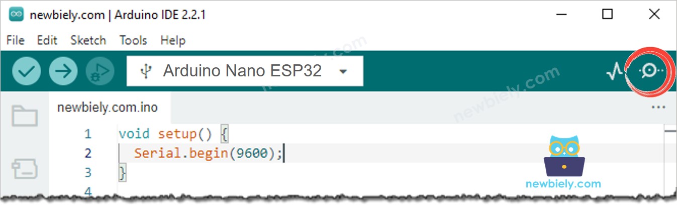
- Copy the above code and paste it to Arduino IDE.
- Compile and upload code to Arduino Nano ESP32 board by clicking Upload button on Arduino IDE
- Open Serial Monitor on Arduino IDE
- Radiates light to sensor
- Check out the result on the Serial Monitor. It looks like the below::
Light Sensor and LED
Wiring Diagram
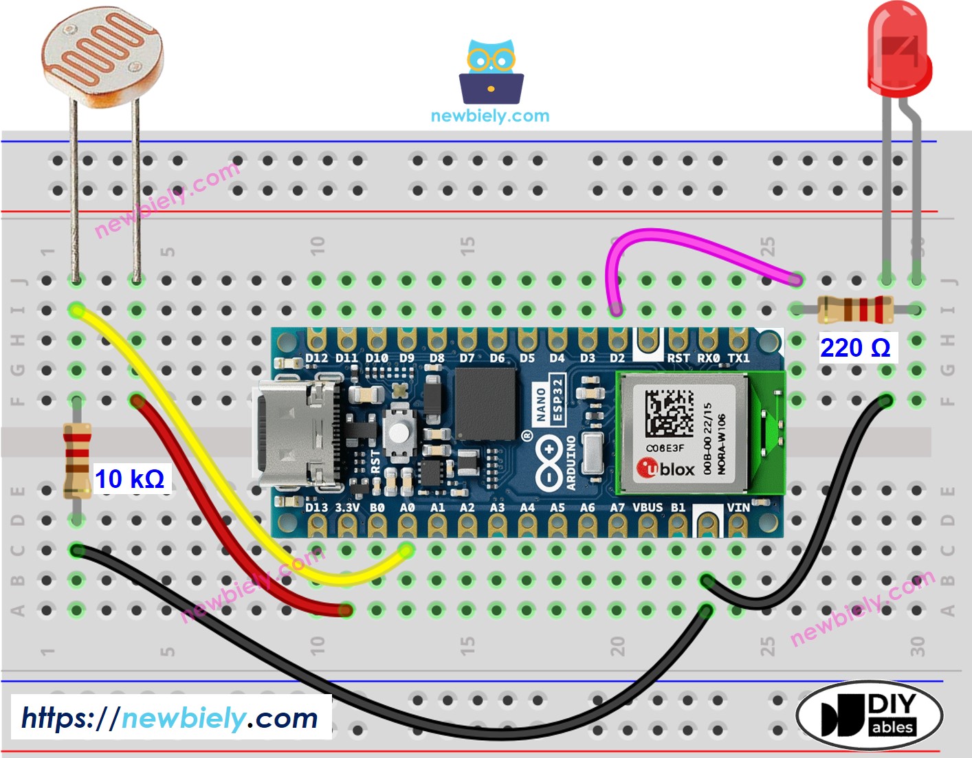
This image is created using Fritzing. Click to enlarge image
Arduino Nano ESP32 Code
The below code turns ON the LED if it is dark, otherwise turns OFF the LED
※ NOTE THAT:
This tutorial uses the analogRead() function to read values from an ADC (Analog-to-Digital Converter) connected to a sensor or component. The Arduino Nano ESP32's ADC is suitable for projects that do not require high accuracy. However, for projects needing precise measurements, keep the following in mind:
- The Arduino Nano ESP32's ADC is not perfectly accurate and might require calibration for correct results. Each Arduino Nano ESP32 board can vary slightly, so calibration is necessary for each individual board.
- Calibration can be challenging, especially for beginners, and might not always yield the exact results you want.
For projects requiring high precision, consider using an external ADC (e.g ADS1115) with the Arduino Nano ESP32 or using another Arduino, such as the Arduino Uno R4 WiFi, which has a more reliable ADC. If you still want to calibrate the Arduino Nano ESP32's ADC, refer to the ESP32 ADC Calibration Driver.