
Arduino Nano 33 IoT - MAX6675 Thermocouple Module
Most beginner temperature sensors give up long before things get interesting - a DHT11 or a DS18B20 will happily quit somewhere around 100°C. If you need to keep an eye on a soldering iron tip, a kiln, a home roaster, or the exhaust of a small engine, you need a completely different kind of sensor: a thermocouple. This tutorial walks you through wiring a MAX6675 Type-K thermocouple module to an Arduino Nano 33 IoT and reading out the temperature, in both Celsius and Fahrenheit, on the Serial Monitor.
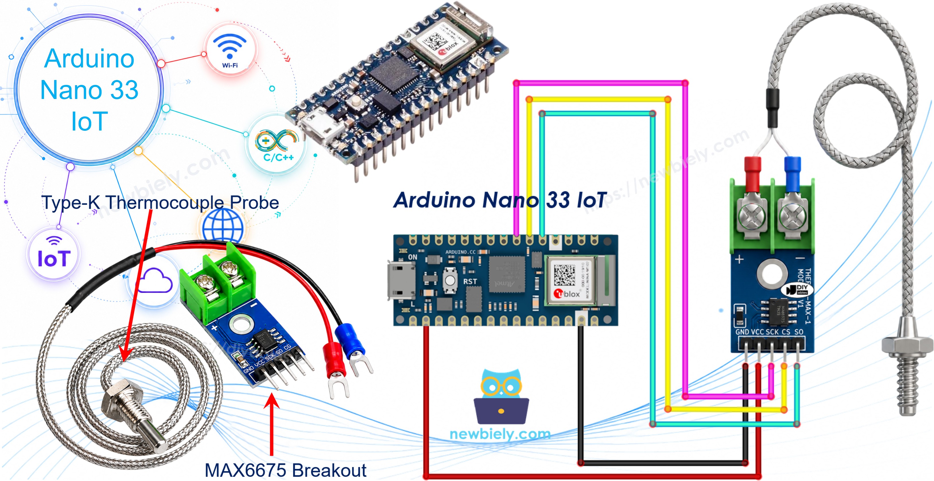
Hardware Preparation
Or you can buy the following kits:
| 1 | × | DIYables Sensor Kit (18 sensors/displays) |
Additionally, some of these links are for products from our own brand, DIYables .
What Exactly Is a Thermocouple?
A thermocouple is simply two different metal wires welded together at one end, called the hot junction. Heat that joint up, and it produces a tiny voltage that rises and falls with the temperature - a quirk of physics known as the Seebeck effect. Because there is no delicate silicon chip sitting at the tip, a thermocouple can survive being stuck directly into flame, molten metal, or an oven far past the point where a normal sensor would melt.
The wire pairing used in this tutorial is Type-K (Chromel and Alumel), the most widely sold thermocouple type around. A Type-K probe is rated from roughly -328°F up to +2300°F, although the specific probe bundled with the MAX6675 module you'll buy is limited to a much narrower range, described below.
MAX6675 Module Pinout
A raw thermocouple only outputs a few millivolts, far too small and far too noisy for the Arduino Nano 33 IoT to read directly. That's the job of the MAX6675 chip: it amplifies the hot-junction voltage, corrects for the temperature at the connector itself, and hands you back a clean 12-bit digital reading over a simple 3-wire interface.
What you actually purchase is a small breakout board carrying the MAX6675 chip, plus an attached Type-K probe about 18 inches long. On the probe, the red wire is positive and the blue wire is negative; both wires clip into the 2-pin screw terminal on the board marked + and -.
Keep these numbers in mind before you go pointing the probe at something really hot:
- Board operating voltage: 3.0V to 5.5V
- Digital reading range: 0°C to 1024°C
- Probe's own safe range: 0°C to 80°C only (the probe itself, not the chip, is the limiting factor)
- Accuracy: about ±3°C
- Resolution: roughly 0.25°C per step
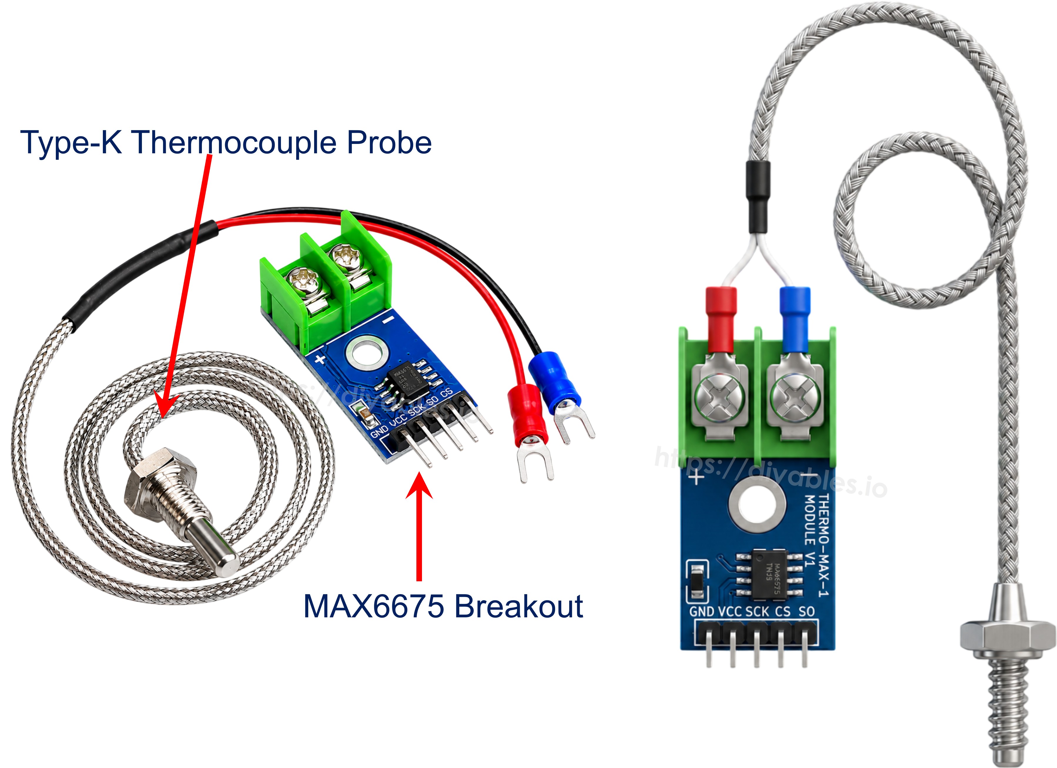
The breakout board exposes five pins:
- GND: ground pin, connect to the Arduino Nano 33 IoT's GND.
- VCC: power pin for the module.
- SCK: serial clock, driven by the Arduino Nano 33 IoT to time each bit of the reading.
- CS: chip select. Pull this low to tell the module you're ready to read a value.
- SO: serial data output (sometimes labeled SO/MISO). This is a read-only line - the module only ever talks, it never listens, so there is no MOSI pin at all.
Wiring Diagram
The Arduino Nano 33 IoT runs its logic at 3.3V, and conveniently the MAX6675 module is happy anywhere from 3.0V to 5.5V, so we'll power it straight from the board's 3.3V rail rather than reaching for an external 5V supply.
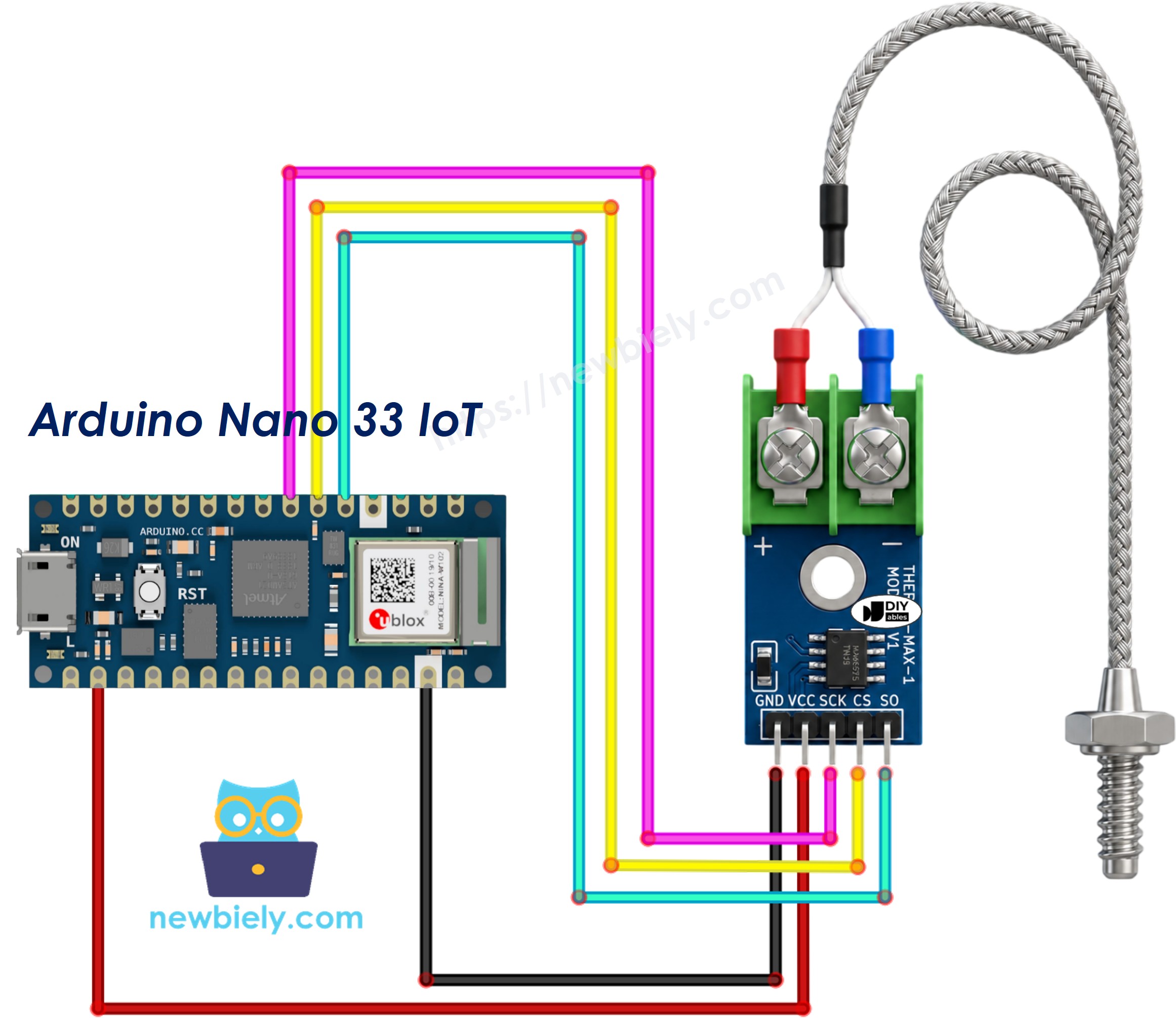
This image is created using Fritzing. Click to enlarge image
| MAX6675 Module | Arduino Nano 33 IoT |
|---|---|
| VCC | 3.3V |
| GND | GND |
| SCK | 4 |
| CS | 3 |
| SO | 2 |
Arduino Nano 33 IoT Code
Detailed Instructions
If you are new to the Arduino Nano 33 IoT, be sure to check out our Getting Started with Arduino Nano 33 IoT tutorial. Then, follow these steps:
- Wire up the MAX6675 module and the Arduino Nano 33 IoT exactly as shown in the diagram above.
- Plug the Arduino Nano 33 IoT into your computer with a USB cable.
- Open the Arduino IDE.
- From the board menu, pick Arduino Nano 33 IoT and select the matching COM port.
- Click the Library Manager icon in the left-hand sidebar.
- Search for MAX6675 and look for the library published by Adafruit.
- Press Install to add it to your IDE.
- Search for MAX6675 library created by Adafruit and click the Install button.
- Paste the code above into a new sketch in the Arduino IDE.
- Hit Upload to compile the sketch and push it onto the Arduino Nano 33 IoT.
- Touch the probe tip to something warm (a mug of hot water works fine for testing) and watch the numbers climb.
- Open the Serial Monitor to watch the live readings.
Note: the MAX6675 chip needs about 220ms between conversions, so hammering it with reads any faster than that will just return the same stale value.
Code Explanation
- Bring in the driver for the module:
- Create a thermocouple object, telling it which three pins carry SCK, CS, and SO:
- Ask the module for a reading in Celsius:
- Or ask for the same reading already converted to Fahrenheit:
- Print both values to the Serial Monitor, then pause briefly before the next reading so the chip has time to settle: