
Arduino UNO Q - TFT LCD Touch Display SPI
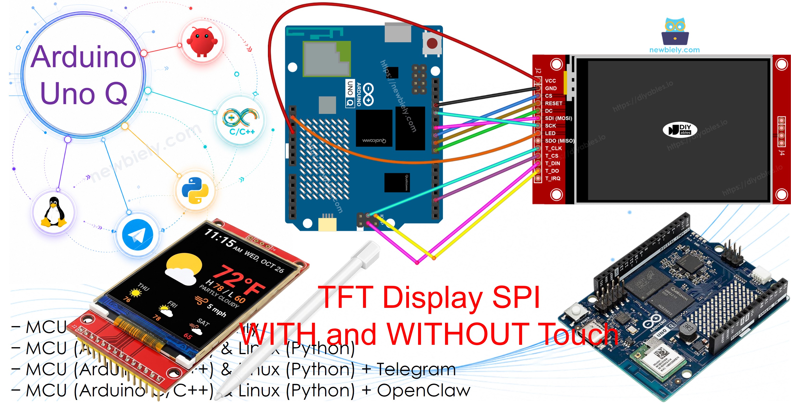
Want to add a colorful screen to your Arduino UNO Q project using just a few wires? This beginner-friendly guide shows you how to use an SPI TFT LCD display with Arduino UNO Q — with or without touch — step by step.
In this tutorial, you will learn:
- What an SPI TFT LCD display is and how it works
- How to wire an SPI TFT display to Arduino UNO Q
- How to program the MCU (C/C++ Arduino code) on Arduino UNO Q to draw shapes and fill areas with color
- How to display text and numbers on the TFT screen
- How to draw bitmap images stored in program memory (PROGMEM)
- How to draw bitmap images loaded from an SD card
- How to render text using a custom external font
- How to read raw touch coordinates from an XPT2046 touch controller
- How to draw on screen by dragging a finger across the display
- How to create interactive touch buttons and calibrate the touch screen
- How to use a secondary or custom SPI bus for the display
- How to program both the Linux side (Python) and MCU side (C/C++) so the Linux side controls the TFT display via Bridge
- How to use Telegram to message Arduino UNO Q to write on the display and read touch points
- How to use OpenClaw on Arduino UNO Q to control the SPI TFT display
This guide covers both touch and non-touch SPI TFT LCD displays. It works with 1.3, 1.54, 2.2, 2.4, 2.8, 3.2, and 3.5 inch panels driven by ILI9341, ILI9488, or ST7789 controller chips.
Tip — simpler and faster alternative: If you want a screen that needs no wiring at all, consider the TFT Touch Shield instead. It plugs directly onto the Arduino UNO Q header — no jumper wires needed. It uses an 8-bit parallel interface, which transfers pixel data significantly faster than SPI.
Hardware Preparation
Or you can buy the following kits:
| 1 | × | DIYables Sensor Kit (18 sensors/displays) |
Additionally, some of these links are for products from our own brand, DIYables .
Note: Unlike a 5V Arduino board, the Arduino UNO Q MCU already runs at 3.3V logic, so no 5V to 3.3V level converter is required for this wiring.
Overview of the SPI TFT LCD Display
An SPI TFT display is a color LCD panel driven by a controller chip over the SPI bus.
Key specs and features:
- Interface: SPI (4-wire) — only a handful of signal wires needed
- Color: Full RGB color, 16-bit or 18-bit depending on the driver chip
- Sizes supported: 1.3, 1.54, 2.2, 2.4, 2.8, 3.2, and 3.5 inch panels
- Touch (optional): XPT2046 / HR2046 / ADS7843 resistive touch controller on the same SPI bus
- MicroSD slot: Present on most modules, also on the shared SPI bus
- Library: DIYables_TFT_SPI — one library for the display and the touch controller
- Logic level: 3.3V — a perfect match for the Arduino UNO Q MCU pins
The DIYables_TFT_SPI library supports three common driver chips:
- ILI9341 — 16-bit RGB565 color, up to 40 MHz SPI
- ILI9488 — 18-bit RGB666 color, up to 24 MHz SPI
- ST7789 — 16-bit RGB565 color, up to 40 MHz SPI
Recommendation: If you have not yet purchased a display, we recommend the ST7789 driver. It is widely available, runs at full 40 MHz SPI speed, and is the most straightforward choice for new projects.
The library extends Adafruit GFX, so all standard drawing and text functions are available.
Pinout
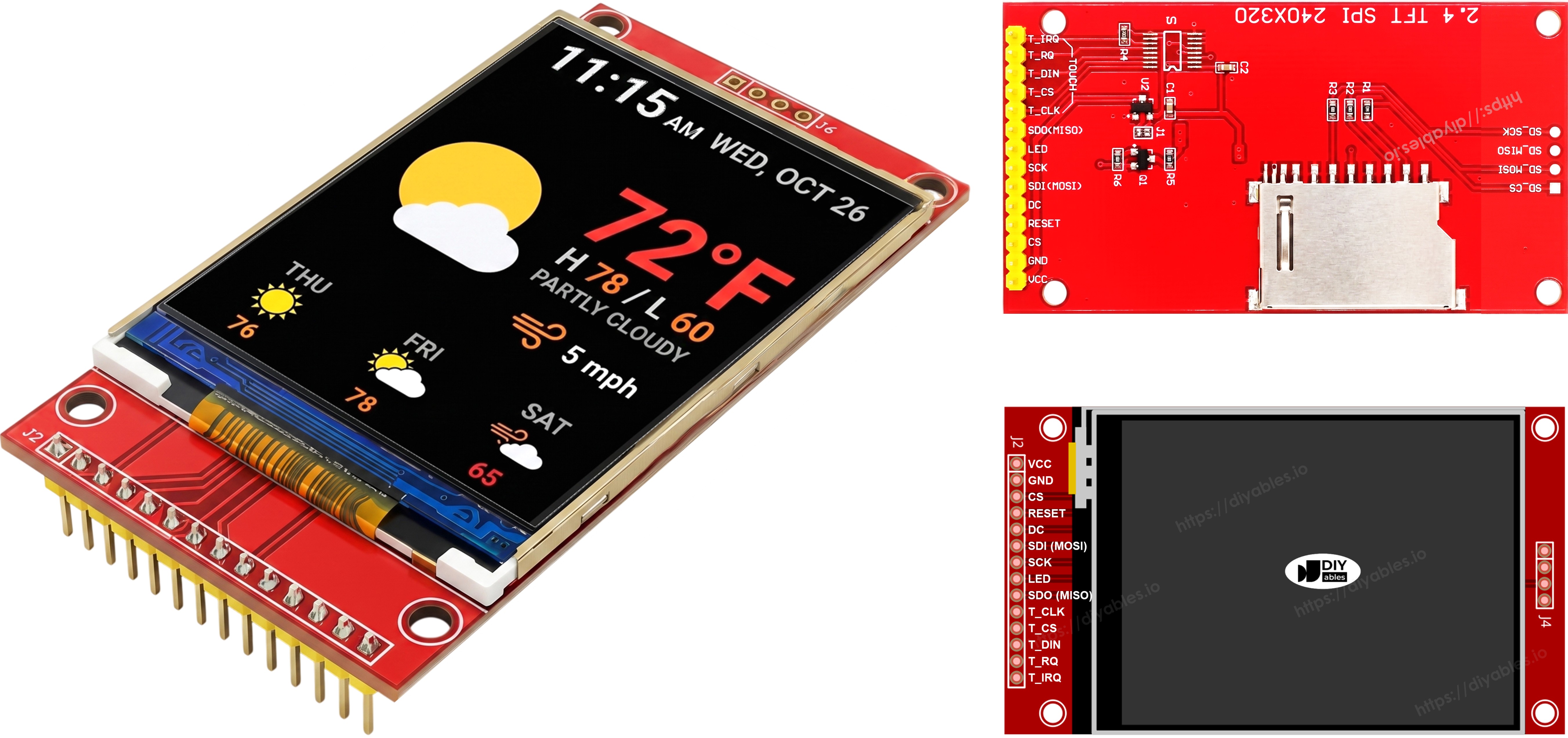
Most SPI TFT LCD displays have the following pins:
Display pins:
| Pin | Function |
|---|---|
| VCC | Power supply |
| GND | Ground |
| CS | Chip Select — pulled low to select the display on the SPI bus |
| DC / RS | Data / Command select — high for pixel data, low for commands |
| RST | Hardware reset — optional; tie to 3.3V if unused |
| MOSI / SDI / SDA | SPI data in (MCU to display) |
| SCK / CLK | SPI clock |
| MISO / SDO | SPI data out (display to MCU) — optional for display-only use |
| LED / BL / BLK | Backlight power — connect to 3.3V or a PWM pin for dimming |
SD card pins (if your application needs to access the SD card):
| Pin | Function |
|---|---|
| SD_CS / TF_CS | SD card Chip Select |
| MOSI / SDI | MOSI — data from MCU to SD card |
| SCK / CLK | SCK — SPI clock |
| MISO / SDO | MISO — data from SD card to MCU |
For TFT displays that support touch, there are additional touch pins (if your application uses the touch function and the display supports it):
| Pin | Function |
|---|---|
| T_CS | Touch controller Chip Select |
| T_CLK | SCK — SPI clock |
| T_DIN | MOSI — data from MCU to touch controller |
| T_DO | MISO — data from touch controller to MCU |
| T_IRQ | Touch interrupt — optional; signals when the screen is being touched |
Note: Some non-touch display modules also expose T_CS, T_CLK, T_DIN, T_DO, and T_IRQ pins. These are non-functional on those boards — the touch controller IC is not populated. They appear because the PCB reuses the same layout as the touch-enabled version to reduce manufacturing variants.
Wiring Diagram
Note — SDO (MISO) is optional: The SDO (MISO) line only carries data from the display back to the board. None of the example code in this tutorial reads from the display, so this pin can be left unconnected. On modules where the touch controller shares the same SPI bus, a connected SDO line can interfere with communication, so leaving it unconnected is recommended.
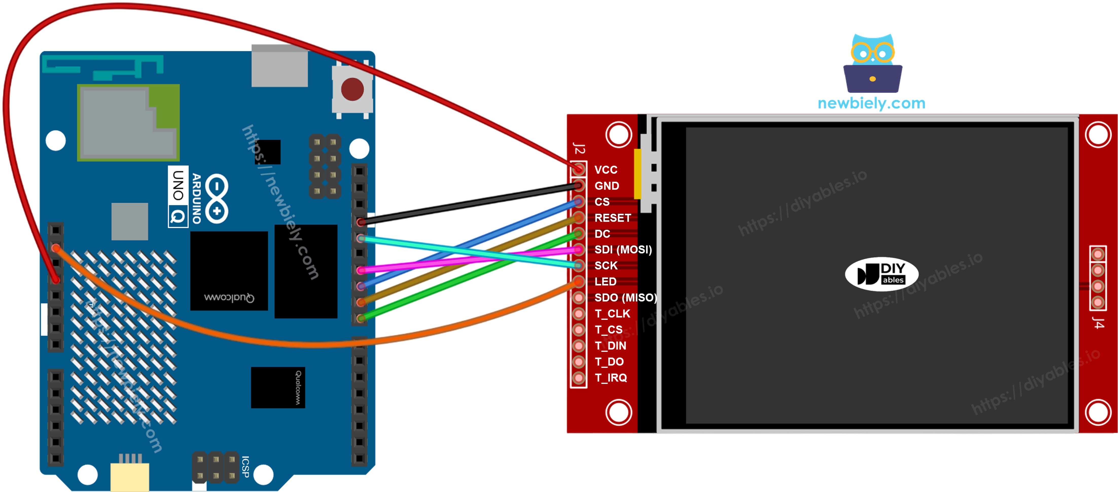
The display connects to the hardware SPI pins on the Arduino UNO Q MCU headers.
- Note: The Arduino UNO Q MCU pins output 3.3V logic, which matches the SPI TFT display — connect the signal lines directly, no level converter needed.
- Note: Connect the TFT VCC pin to the 3.3V pin on the Arduino UNO Q, not to 5V.
- Note: The display, the SD card, and the touch controller all share MOSI (D11), SCK (D13), and MISO (D12). Each one has its own CS pin, so only one is active at a time.
Without Touch
Connect MOSI to D11, SCK to D13, and MISO to D12 on the Arduino UNO Q. CS, DC, and RST can be any available GPIO — D10, D8, D9 are used in the examples.
Display:
| TFT Pin | Arduino UNO Q MCU Pin | Description |
|---|---|---|
| VCC | 3.3V | Power supply |
| GND | GND | Ground |
| CS | D10 | Chip Select |
| DC / RS | D8 | Data / Command select |
| RST | D9 | Reset (optional) |
| MOSI / SDI | D11 | Hardware SPI MOSI |
| SCK | D13 | Hardware SPI clock |
| MISO / SDO | D12 | Hardware SPI MISO (optional) |
| LED / BL | 3.3V | Backlight power |
SD card (if your application needs to access the SD card):
| SD Pin | Arduino UNO Q MCU Pin | Description |
|---|---|---|
| SD_CS / TF_CS | D4 | SD card Chip Select |
| MOSI / SDI | D11 | Shared with display MOSI (D11) |
| SCK / CLK | D13 | Shared with display SCK (D13) |
| MISO / SDO | D12 | Shared with display MISO (D12) |
This image is created using Fritzing. Click to enlarge image
With Touch
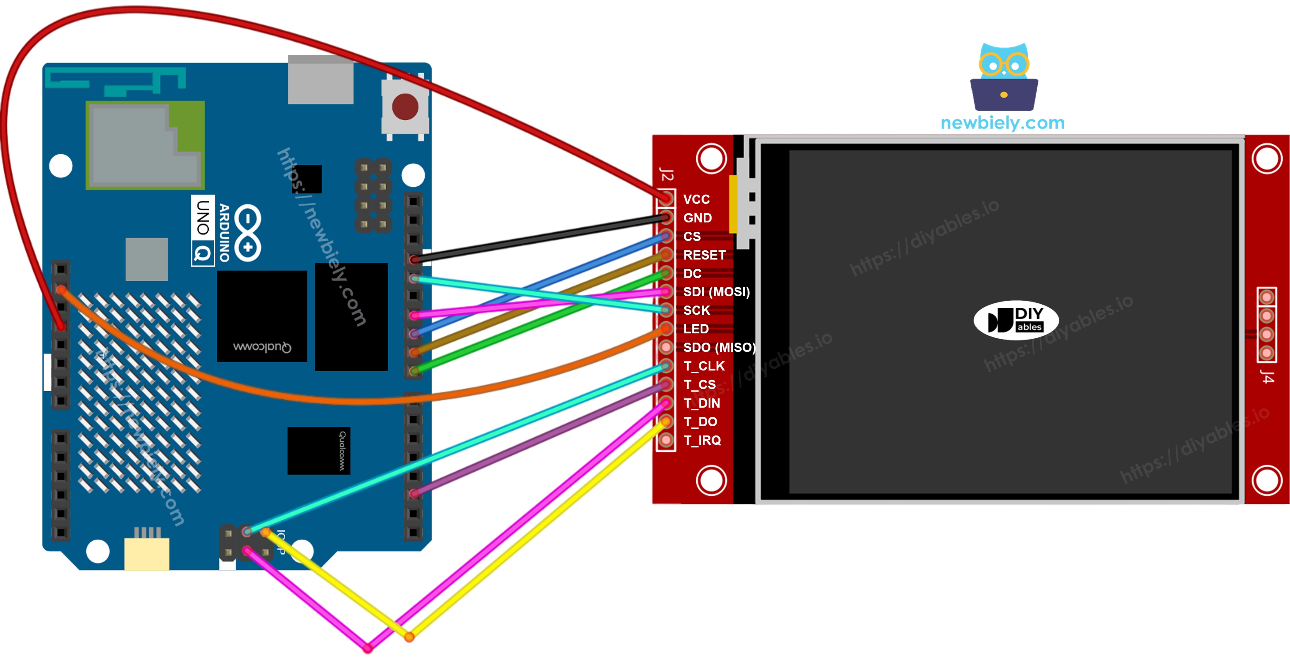
Connect the XPT2046 touch controller to the Arduino UNO Q SPI bus, sharing D11, D13, and D12 with the display.
Display:
| TFT Pin | Arduino UNO Q MCU Pin | Description |
|---|---|---|
| VCC | 3.3V | Power supply |
| GND | GND | Ground |
| CS | D10 | Chip Select |
| DC / RS | D8 | Data / Command select |
| RST | D9 | Reset (optional) |
| MOSI / SDI | D11 | Hardware SPI MOSI |
| SCK | D13 | Hardware SPI clock |
| MISO / SDO | D12 | Hardware SPI MISO (optional) |
| LED / BL | 3.3V | Backlight power |
Touch controller (if your application uses the touch function and the display supports it):
| Touch Pin | Arduino UNO Q MCU Pin | Description |
|---|---|---|
| T_CS | D2 | Touch Chip Select |
| T_IRQ | D2 | Touch interrupt (optional) |
| T_DIN | D11 | Shared with display MOSI (D11) |
| T_CLK | D13 | Shared with display SCK (D13) |
| T_DO | D12 | Shared with display MISO (D12) |
This image is created using Fritzing. Click to enlarge image
The Arduino UNO Q MCU exposes one hardware SPI interface on the Uno headers, so all three peripherals — display, SD card, and touch controller — share the same three data lines. The DIYables_TFT_SPI library manages both the display and the XPT2046 touch controller through a single API, so no separate SPI library is needed for the touch side.
Arduino UNO Q Code — Minimal Sketch Structure
The Arduino UNO Q has two processors working together:
- The STM32 MCU drives the SPI TFT display and reads the touch controller — it renders all text and graphics in real time
- The Qualcomm MPU runs Debian Linux and handles Wi-Fi, Python, and cloud connectivity
- In this section, only the MCU is programmed — the Linux side stays idle. A later section shows how both processors work together via Bridge.
All sketches using the DIYables_TFT_SPI library share this skeleton:
Pass the physical pixel dimensions of your panel to the constructor. Modules with the same driver chip come in different sizes.
Arduino UNO Q Code — Draw Shapes
The sketch below demonstrates the Adafruit GFX drawing primitives on your SPI TFT display: circles, triangles, rectangles, rounded rectangles, and lines.
What the code does:
- Creates the display object for your driver chip
- Initializes the panel and sets landscape rotation
- Scales every shape position to the real screen size
- Redraws the whole grid of colored shapes every 10 seconds
Detailed Instructions
First time with Arduino UNO Q? Follow the Getting Started with Arduino UNO Q tutorial to get your development environment ready before proceeding.
- Connect: Wire the SPI TFT display to the Arduino UNO Q as shown in the wiring diagram, then plug in the USB-C cable.
- Open Arduino App Lab: Launch Arduino App Lab and wait until it detects your Arduino UNO Q — this can take several minutes on first launch.
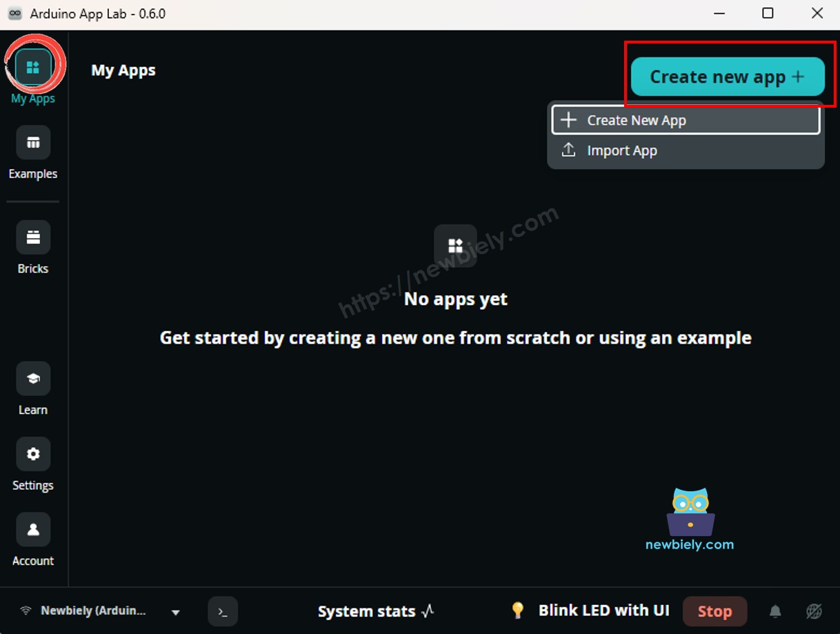
- Create a new App: Click the Create New App button.
- Give the App a name, for example: DIYables_TftSpi
- Click Create to confirm.
- You will see a set of folders and files generated inside your new App.
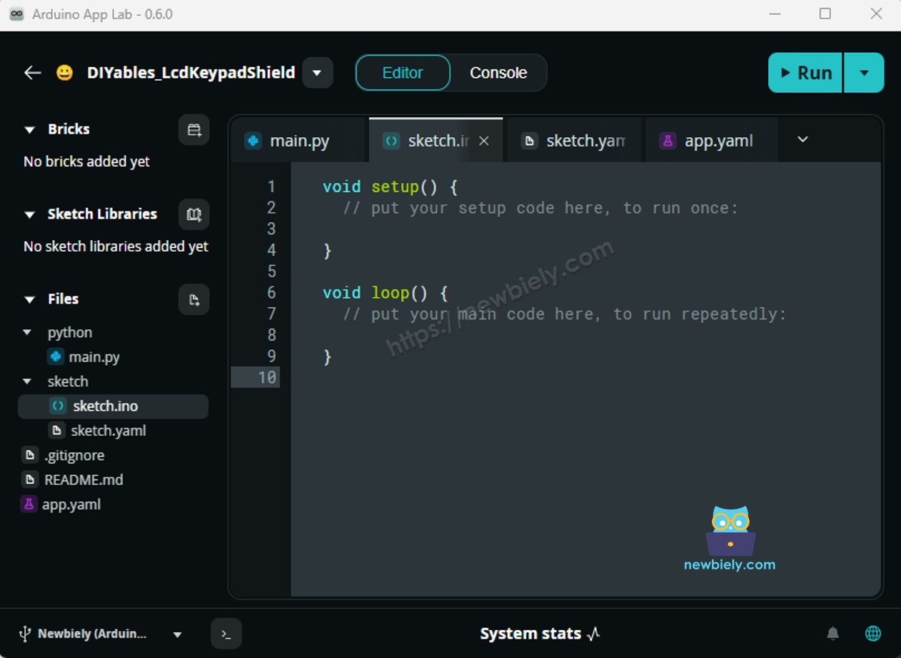
- Find the sketch/sketch.ino file — this is where you will paste the MCU sketch.
- Install the library: Click the Add sketch library button (the open book icon with a + sign) in the left sidebar.
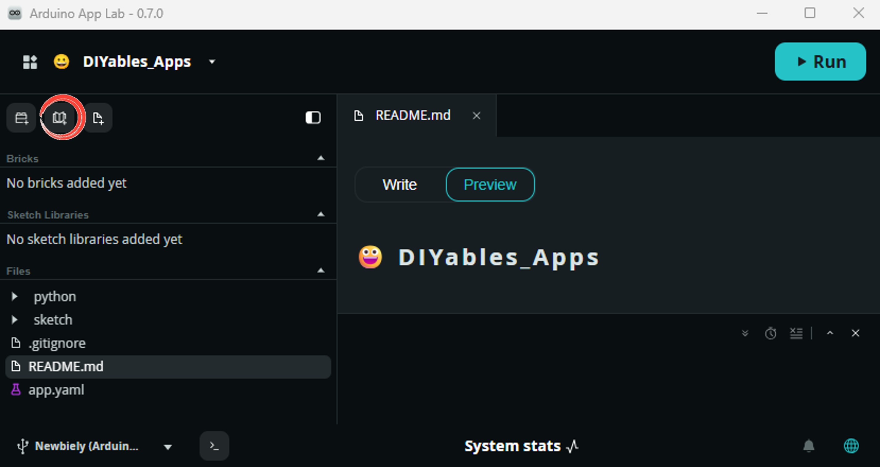
- Search for Arduino_RouterBridge created by Arduino and click the Install button.
- Search for DIYables TFT SPI created by DIYables.io and click the Install button.
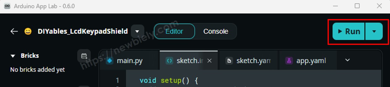
- Upload: Click the Run button in Arduino App Lab to compile and upload to the STM32.
The display shows a grid of colored shapes that refreshes every few seconds!
- Pro Tip: Set the width and height in the constructor to the real pixel size of your panel. A mismatch here is the most common cause of a shifted or clipped image.
Method Quick Reference
| Method | What It Does | Usage |
|---|---|---|
| begin() | Initialize the display controller. Call once in setup(). | TFT_display.begin(); |
| setRotation(r) | Rotate the coordinate system. 0=portrait, 1=landscape. | TFT_display.setRotation(1); |
| fillScreen(color) | Clear screen with a solid color. | TFT_display.fillScreen(WHITE); |
| colorRGB(r,g,b) | Build a 16-bit RGB565 color from 8-bit components. | colorRGB(0, 128, 255) |
| fillCircle(x,y,r,color) | Draw a solid circle. | TFT_display.fillCircle(80, 80, 40, RED); |
| fillRect(x,y,w,h,color) | Draw a solid rectangle. | TFT_display.fillRect(10, 10, 60, 40, BLUE); |
| drawRoundRect(x,y,w,h,r,color) | Draw a rounded rectangle outline. | TFT_display.drawRoundRect(5,5,100,50,10,GREEN); |
Arduino UNO Q Code — Show Text and Number
This sketch shows how to print strings and numbers at different sizes, colors, and positions on the SPI TFT display.
What the code does:
- Fills the screen with white
- Sets a magenta text color and a large text size
- Prints a temperature value with one decimal place and a degree symbol
- Prints a humidity value on the next line
Detailed Instructions
- Copy the code above and paste it into sketch/sketch.ino.
- Click the Run button in Arduino App Lab.
The display prints the temperature and humidity values in large magenta text.
Method Quick Reference
| Method | What It Does | Usage |
|---|---|---|
| setTextColor(color) | Set text foreground color. | TFT_display.setTextColor(BLACK); |
| setTextSize(size) | Scale text. Size 1 is 6x8 pixels. | TFT_display.setTextSize(2); |
| setCursor(x, y) | Position the text cursor. | TFT_display.setCursor(10, 30); |
| print(value) | Print a string or number at the cursor. | TFT_display.print("Temp: "); |
| println(value) | Print and advance to next line. | TFT_display.println(25.4); |
Arduino UNO Q Code — Draw Image
This sketch displays a full-color RGB565 bitmap image stored in program memory. The image data is declared in bitmap.h as a const uint16_t array marked PROGMEM. This keeps the pixel data in flash rather than SRAM, so the display works correctly even when RAM is tight. Copy bitmap.h into the sketch folder before compiling.
What the code does:
- Includes the bitmap array from bitmap.h
- Reads the real screen size to center the image
- Draws the RGB565 bitmap at the centered position
- Inverts the display colors every 2 seconds as a simple effect
Detailed Instructions
- Copy the code above and paste it into sketch/sketch.ino.
- Create a new file named bitmap.h in the same folder as the sketch:
- In Arduino App Lab, right-click the sketch/ folder and choose New File.
- Name it bitmap.h.
- Copy the bitmap array below and paste it into bitmap.h. This array contains the DIYables logo.
- Update img_width and img_height in the sketch with your image dimensions.
- Click the Run button in Arduino App Lab.
- Prepare your image (JPEG or PNG format).
- Convert it to a bitmap array using the Image to Bitmap Converter tool.
- Upload your picture and set the size to fit your panel.
- For transparent PNGs, choose a background color.
- Click Convert, then copy the generated array into bitmap.h.
- Update img_width and img_height, then click Run again.
The display shows the bitmap image loaded from program memory.
To use your own image, follow these steps:
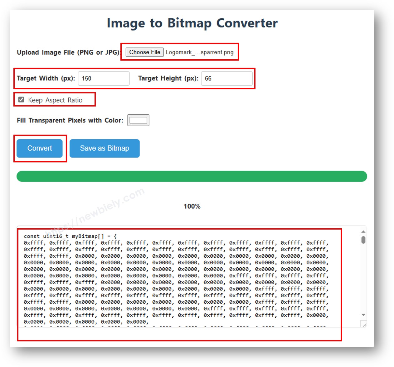
Note: If you change bitmap.h and the sketch does not recompile, add a space anywhere in the sketch file to force a rebuild.
Method Quick Reference
| Method | What It Does | Usage |
|---|---|---|
| drawRGBBitmap(x,y,bitmap,w,h) | Draw an RGB565 PROGMEM bitmap starting at pixel (x, y). | TFT_display.drawRGBBitmap(0, 0, myImage, 240, 320); |
| fillScreen(color) | Clear the screen before drawing the image. | TFT_display.fillScreen(BLACK); |
| invertDisplay(flag) | Invert the panel colors on or off. | TFT_display.invertDisplay(true); |
Arduino UNO Q Code — Draw Image from SD Card
This sketch reads a 24-bit BMP image file from a micro SD card and pushes pixel data to the display in small chunks. This approach streams the image without ever holding the full image in RAM, making it practical for large panels.
Connect the SD card to the same SPI bus as the display. Share MOSI (D11), SCK (D13), and MISO (D12). Assign a separate CS pin to the SD module — it is defined as SD_CS in the sketch (D4).
What the code does:
- Initializes the SD card on its own CS pin
- Reads the BMP header to get the image width and height
- Centers the image on the screen
- Streams the pixels row by row and draws them on the TFT display
- Prints progress and error messages to the App Lab console
Detailed Instructions
- Download diyables.bmp and copy it to the root of your Micro SD Card.
- Insert the Micro SD Card into the card slot on the display module.
- Copy the code above and paste it into sketch/sketch.ino.
- Click the Run button in Arduino App Lab.

- Open the Console tab and select the Serial Monitor subtab to see the progress messages.
The image is read from the card and displayed on screen.
To use your own image:
- Use the Image to Bitmap Converter to convert your image — click Save as Bitmap to download the .bmp file.
- Keep the filename short (fewer than 9 characters, not counting .bmp).
- Copy the .bmp file to the Micro SD Card, update the filename in the sketch, and click Run.
App Lab Console Output
Method Quick Reference
| Method | What It Does | Usage |
|---|---|---|
| SD.begin(cs) | Initialize the SD card on its own chip select pin. | SD.begin(SD_CS); |
| SD.open(name) | Open a file stored on the SD card. | File f = SD.open("diyables.bmp"); |
| width() / height() | Get the current screen size after rotation. | uint16_t w = TFT_display.width(); |
| drawPixel(x,y,color) | Draw a single pixel in the given color. | TFT_display.drawPixel(10, 20, color); |
Arduino UNO Q Code — Use External Font
This sketch renders on-screen text using a custom Adafruit GFX-compatible font. Compared to the built-in 5x7 bitmap font, custom fonts give better readability and styling. The font file is included as a header and activated with a single call to setFont().
What the code does:
- Includes the FreeSansBold12pt7b font header
- Activates the font with setFont()
- Prints the same temperature and humidity values as before, now in the custom font
Detailed Instructions
- Copy the code above and paste it into sketch/sketch.ino.
- Click the Run button in Arduino App Lab.
The display renders text in the custom font. Notice the improved glyph quality compared to the built-in font.
Important: Some custom fonts do not include special characters such as the degree symbol. The built-in font does support them.
Method Quick Reference
| Method | What It Does | Usage |
|---|---|---|
| setFont(&FontName) | Activate a custom GFX-compatible font. Pass NULL to restore the built-in 5x7 font. | TFT_display.setFont(&FreeSans12pt7b); |
| setCursor(x, y) | Move the text cursor to the given position. | TFT_display.setCursor(10, 40); |
| setTextColor(color) | Set the text foreground color. | TFT_display.setTextColor(WHITE); |
| print(text) | Print a string at the current cursor position using the active font. | TFT_display.print("Hello!"); |
Arduino UNO Q Code — Touch Get Point
This sketch reads touch coordinates from the XPT2046 touch controller, prints them to the Arduino App Lab console, and draws a red dot at the touched location. Running this first helps you see the numeric range of your specific panel.
Wiring: T_CLK to D13, T_DIN to D11, T_DO to D12 (shared SPI bus with the display). T_CS to D7, T_IRQ to D2 or left unconnected.
What the code does:
- Initializes the XPT2046 on the shared SPI bus
- Applies the default touch calibration values
- Waits for a touch and reads the screen coordinates
- Prints the coordinates to the console and marks the point with a red dot
Detailed Instructions
- Copy the code above and paste it into sketch/sketch.ino.
- Click the Run button in Arduino App Lab.
- Open the Console tab and select the Serial Monitor subtab.
- Touch the screen and watch the coordinates appear!
App Lab Console Output
Method Quick Reference
| Method | What It Does | Usage |
|---|---|---|
| initTouchSPI(cs, irq) | Initialize the XPT2046 on the shared SPI bus. Use -1 for irq if the interrupt pin is not connected. | TFT_display.initTouchSPI(7, 2); |
| setTouchCalibration(minX,maxX,minY,maxY) | Map raw ADC values to screen pixel coordinates. | TFT_display.setTouchCalibration(300, 3700, 300, 3700); |
| getTouch(x, y) | Retrieve calibrated touch coordinates in screen pixels. Returns true when pressed. | if (TFT_display.getTouch(x, y)) { ... } |
| readTouchRaw(x, y, z) | Return raw ADC touch values without applying any calibration. | TFT_display.readTouchRaw(x, y, z); |
Arduino UNO Q Code — Touch Draw
This sketch turns the SPI TFT touch screen into a simple finger-drawing pad. Calibrated touch coordinates place small filled circles at each point the finger contacts, building up a continuous drawing as it moves.
What the code does:
- Sets up the display and the XPT2046 touch controller
- Continuously checks whether the screen is being pressed
- Draws a small red dot at each touch point
Detailed Instructions
- Copy the code above and paste it into sketch/sketch.ino.
- Click the Run button in Arduino App Lab.
You can now draw on the screen:
- Touch and drag on the screen to paint.
- Lift your finger to stop drawing.
- Touch again to continue.
Method Quick Reference
| Method | What It Does | Usage |
|---|---|---|
| initTouchSPI(cs, irq) | Set up the XPT2046 on the shared SPI bus. | TFT_display.initTouchSPI(7, -1); |
| setTouchInvertX(invert) / setTouchInvertY(invert) | Flip the touch axis when X or Y is mirrored on your panel. Call BEFORE setTouchCalibration(). | TFT_display.setTouchInvertY(true); |
| getTouch(x, y) | Retrieve calibrated touch coordinates. Returns true while pressed. | if (TFT_display.getTouch(x, y)) { ... } |
| fillCircle(x, y, r, color) | Draw a small dot at the touch point. | TFT_display.fillCircle(x, y, 3, RED); |
Arduino UNO Q Code — Touch Button
This sketch draws a rectangular button on the screen and checks touch coordinates against the button bounds. When the button is tapped it highlights and prints an event to the App Lab console. This is the simplest way to build a touch-driven user interface.
The T_IRQ pin is optional for this example. Pass -1 as the irq argument if you prefer not to connect it.
What the code does:
- Draws a red button labeled "PRESS"
- Checks whether each touch falls inside the button rectangle
- Debounces the press so a single tap gives a single event
- Redraws the button in gray with "PRESSED" and logs press and release events
Detailed Instructions
- Copy the code above and paste it into sketch/sketch.ino.
- Click the Run button in Arduino App Lab.
- Open the Console tab and select the Serial Monitor subtab.
- Tap the button on screen — it changes color while pressed.
App Lab Console Output
Method Quick Reference
| Method | What It Does | Usage |
|---|---|---|
| initTouchSPI(cs, irq) | Initialize the XPT2046. Pass -1 for irq to poll without the interrupt pin. | TFT_display.initTouchSPI(7, -1); |
| setTouchCalibration(minX,maxX,minY,maxY) | Apply calibration so getTouch() returns display-pixel coordinates. | TFT_display.setTouchCalibration(300, 3700, 300, 3700); |
| getTouch(x, y) | Get the current calibrated touch position. Returns true while the screen is pressed. | if (TFT_display.getTouch(x, y)) { ... } |
| fillRect(x, y, w, h, color) | Draw a solid colored rectangle for the button background. | TFT_display.fillRect(10, 10, 120, 60, BLUE); |
Arduino UNO Q Code — Touch Calibration
The touch examples above use default calibration values and work on most panels. If the touch position is not accurate, run this sketch to measure the raw ADC range of your own XPT2046 panel. Touch each corner when prompted, then copy the four printed numbers into setTouchCalibration() in your other touch sketches.
Calibration is needed because the resistive touch layer does not align perfectly with the display pixels due to manufacturing differences. It only needs to be done once per display.
What the code does:
- Blinks a red dot in each of the four corners, numbered 1 to 4
- Averages several raw readings while you hold each corner
- Prints live raw Z, X, and Y values so you can confirm touch is detected
- Prints a ready-to-use setTouchCalibration() line at the end
Detailed Instructions
- Copy the code above and paste it into sketch/sketch.ino.
- Click the Run button in Arduino App Lab.
- Open the Console tab and select the Serial Monitor subtab.
- Press and hold each blinking corner dot in order: top-left, top-right, bottom-right, bottom-left.
- Copy the printed setTouchCalibration() line into the setup() of your other touch sketches.
App Lab Console Output
Method Quick Reference
| Method | What It Does | Usage |
|---|---|---|
| initTouchSPI(cs, irq) | Initialize the XPT2046 touch controller. | TFT_display.initTouchSPI(7, 2); |
| readTouchRaw(x, y, z) | Read raw ADC values to measure the calibration range. | TFT_display.readTouchRaw(x, y, z); |
| setTouchCalibration(minX,maxX,minY,maxY) | Store the calibration values so getTouch() maps correctly to pixel coordinates. | TFT_display.setTouchCalibration(305, 3696, 297, 3703); |
| setTouchInvertX(invert) / setTouchInvertY(invert) | Flip the touch axis when X or Y is mirrored on your panel. Call BEFORE running calibration so the stored values match. | TFT_display.setTouchInvertY(true); |
Arduino UNO Q Code — Custom SPI Bus
This sketch shows how to supply an explicit SPIClass instance to the display constructor. Use this approach when you want to name the bus explicitly, share it with extra configuration, or move the display to a second SPI interface on boards that have one.
The Arduino UNO Q MCU exposes a single hardware SPI bus on D11, D13, and D12, so MY_SPI stays as &SPI here. The same sketch runs unchanged on boards with two buses by swapping that one define.
What the code does:
- Defines MY_SPI as a pointer to the SPI bus to use
- Passes that pointer as the last constructor argument
- Draws a red, green, and blue color-bar test pattern
- Prints a confirmation label over the bars
Detailed Instructions
- Copy the code above and paste it into sketch/sketch.ino.
- Click the Run button in Arduino App Lab.
The display starts up on the explicit SPI bus and renders the color-bar test pattern.
Method Quick Reference
| Method | What It Does | Usage |
|---|---|---|
| DIYables_ILI9341_SPI(w,h,cs,dc,rst,spi) | Constructor variant that accepts a pointer to any SPIClass. Defaults to &SPI when the argument is omitted. | DIYables_ILI9341_SPI tft(240, 320, 10, 9, 8, &SPI); |
| begin() | Initialize the display on the configured SPI bus. | TFT_display.begin(); |
Bridge: Linux + MCU
This section shows how to program both processors of the Arduino UNO Q so the Linux side can control the SPI TFT display and read touch input remotely:
- The SPI TFT display and the XPT2046 touch controller are connected to the MCU (STM32) — the MCU renders all output and reads every touch
- The MPU cannot drive the TFT or read touch directly — it must request results from the MCU via Bridge.call(), which triggers the matching Bridge.provide() callback on the MCU
- The MPU has Wi-Fi — running full Debian Linux, it can reach the Internet, call REST APIs, and push display updates from anywhere
- Arduino_RouterBridge enables RPC communication between the two processors — the Arduino Router service on Linux manages all traffic
- ⚠️ /dev/ttyHS1 (Linux) and Serial1 (MCU) are RESERVED by the router — never open them in user code
In short: MCU drives the SPI TFT display and reads touch → MPU requests commands and touch data → MPU uses them over the Internet.
MCU Code (Bridge)
Python Code (Bridge)
Detailed Instructions
- Connect: Wire the SPI TFT display and the XPT2046 touch controller to the Arduino UNO Q, then plug in the USB-C cable.
- Open Arduino App Lab: Launch Arduino App Lab and wait for the board to be detected.
- Create a new App: Click Create New App, name it DIYables_TftSpiBridge, then click Create.
- Paste the MCU sketch: Copy the MCU Bridge code above and paste it into sketch/sketch.ino.
- Paste the Python code: Copy the Python Bridge code above and paste it into the Python file in the App.
- Install the library: Click the Add sketch library button (the open book icon with a + sign) in the left sidebar.
- Search for Arduino_RouterBridge created by Arduino and click the Install button.
- Search for DIYables TFT SPI created by DIYables.io and click the Install button.
- Upload: Click the Run button in Arduino App Lab.
- Note: Make sure Bridge.begin() is called in the MCU sketch and the sketch is uploaded before running the Python script on the Linux side.
- ⚠️ Warning: Never directly open /dev/ttyHS1 (on Linux) or use Serial1 (on MCU) in your code — these are reserved by the Arduino Router and accessing them will break the Bridge.
App Lab Console Output
Telegram
Control the SPI TFT display from anywhere using Telegram. Send a message from your phone and the display updates in real time — and ask the board where you last touched the screen.
If you do not have a Telegram bot yet, see How to Create a Telegram Bot to get your bot token before continuing.
This section covers:
- Running a Python script on the Linux side of Arduino UNO Q to listen for Telegram messages
- Forwarding commands from Telegram to the MCU side to write on the SPI TFT display
- Sending the MCU result — the display status or the last touch point — back as a Telegram reply
MCU sketch: Keep the same MCU sketch from the previous Bridge section — no changes needed. Make sure it is already uploaded and running on the STM32 before proceeding.
Python Code (Telegram)
Detailed Instructions
- Replace YOUR_TELEGRAM_BOT_TOKEN with your actual bot token from BotFather.
- Replace YOUR_CHAT_ID with your Telegram chat ID.
- Paste this Python code into your App's Python file, keeping the same MCU sketch from the Bridge section.
- Click the Run button in Arduino App Lab.
- Open Telegram and send /start to your bot to see the command list.
- Note: Replace YOUR_BOT_TOKEN with the token obtained from @BotFather on Telegram.
App Lab Console Output


ArduinoBot
OpenClaw
You can adapt the OpenClaw to this tutorial by refering the instruction on Arduino Uno Q - OpenClaw Tutorial
Troubleshooting
If the display does not behave as expected, check these first:
- Black screen — Confirm CS, DC, MOSI, and SCK are all connected. A missing CS line leaves the display inactive.
- Wrong driver — Only one constructor line should be active. The other two must stay commented out.
- Shifted or clipped image — The width and height in the constructor must match the physical panel size.
- Nothing on a bright backlight — Check that VCC and LED / BL are on 3.3V, not 5V.
- Touch not working — Run the Touch Calibration sketch to get calibration values specific to your panel.
- Touch axis reversed — Call setTouchInvertX(true) or setTouchInvertY(true) before setTouchCalibration().
Platform Support
The DIYables_TFT_SPI library relies only on standard Arduino APIs — SPI, digitalWrite, and millis:
- It runs on the Arduino UNO Q MCU (STM32) through Arduino App Lab
- The same sketches also run unchanged on other Arduino-compatible boards
- Only the pin numbers and the panel size in the constructor need adjusting between boards
Project Ideas
You can build many creative projects using an SPI TFT display with Arduino UNO Q:
- Wi-Fi Weather Dashboard: The Linux side pulls a forecast from an online API and the MCU paints it on the TFT screen
- Touch Control Panel: Draw on-screen buttons that switch LEDs, relays, or motors wired to the MCU
- Remote Message Board: Send text via Telegram that appears instantly on the display anywhere in the world
- Photo Frame: Cycle through BMP images stored on the Micro SD Card as a slideshow
- Signature Pad: Capture a finger-drawn signature and let the Linux side upload it to the cloud
- Live Sensor Monitor: Show temperature, humidity, or distance readings as large, easy-to-read numbers
Challenge Yourself
Ready to go further with the SPI TFT display on Arduino UNO Q? Try these challenges:
- Easy: Change the pen color and radius in the Touch Draw sketch so each new touch paints in a different color.
- Medium: Add a second on-screen button next to the first one, and print a different message for each button in the App Lab console.
- Advanced: Build a Telegram-controlled dashboard: the Python side fetches live weather data over Wi-Fi, sends it via Bridge, and the MCU draws a temperature gauge with a colored bar on the SPI TFT display.