
Arduino UNO Q - PC817 Optocoupler: Monitor 12V/24V DC Input Signal
A PC817 optocoupler lets the Arduino UNO Q watch a 12V or 24V circuit through a beam of light instead of a wire, so nothing from the high-voltage side can ever reach the board. That matters a lot on the UNO Q, because behind the 3.3V STM32 MCU sits a Qualcomm processor running Debian Linux — a board you really do not want to lose to a 24V spike from a machine cabinet.
Nine times out of ten the reason for building this circuit is a plain question about a device: is that machine actually running right now? Hang a PC817 optocoupler module across a machine's 24V run lamp and the answer becomes a digital pin — one the STM32 reads, the Linux side logs, and Telegram announces.
In this tutorial, you will learn:
- What a PC817 optocoupler is and why an isolated digital input protects the Arduino UNO Q
- Which of the three PC817 module variants — 3-5V, 12V or 24V — matches the signal you want to watch
- How to wire a PC817 optocoupler module to the Arduino UNO Q, and how to build the same thing from the bare 4-pin chip instead
- How to tap the module in parallel across a device to monitor whether it is on or off, without altering the device's own circuit
- How to find out whether your module is active-LOW or active-HIGH, and the single constant that flips it in code
- How to expose the isolated input to the Linux side of the Arduino UNO Q through Bridge
- How to get a Telegram alert the instant a 24V machine line goes live or goes dead
- How to use OpenClaw on Arduino UNO Q with the PC817 optocoupler
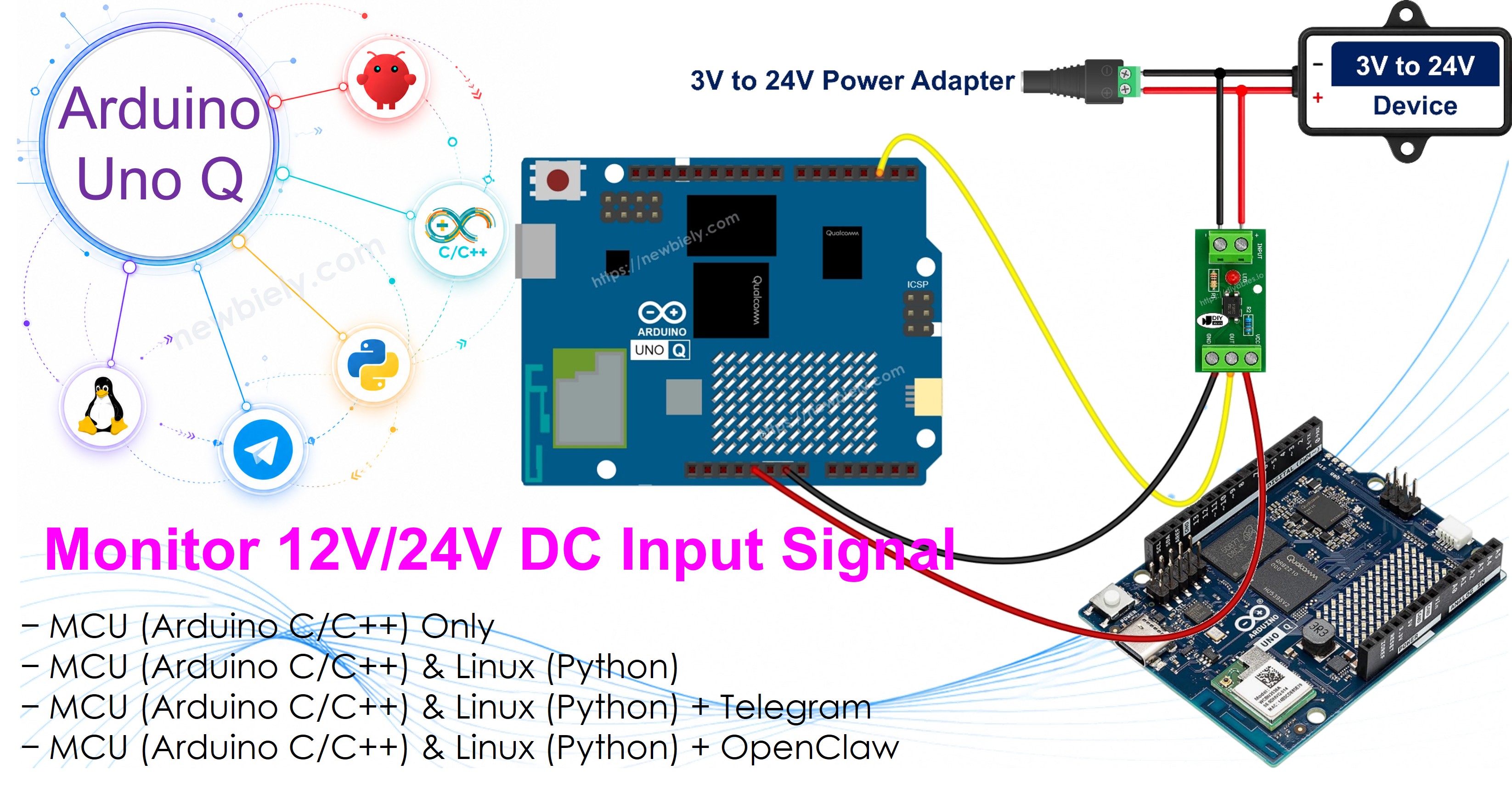
Hardware Preparation
Or you can buy the following kits:
| 1 | × | DIYables Sensor Kit (18 sensors/displays) |
Additionally, some of these links are for products from our own brand, DIYables .
You need one module variant - the next section says which.
Overview of the PC817 Optocoupler
Inside the PC817 there is an infrared LED facing a phototransistor across an insulating gap. When current flows through the LED, its light switches the transistor on, so the signal crosses as light instead of electricity — which is why the two sides stay electrically separate. The datasheet rates that gap at 5000 Vrms for one minute.
Key numbers from the Sharp datasheet, which apply just as much to the PC817 sitting on a ready-made module:
| Parameter | Value |
|---|---|
| LED forward voltage (Vf) | about 1.2 V typical, 1.4 V max |
| LED forward current (If) | 5-20 mA normal, 20 mA continuous max |
| Collector-emitter voltage (VCEO) | 35 V max |
| Collector current (IC) | 50 mA max |
| Collector power dissipation | 150 mW |
| Isolation voltage | 5000 Vrms (1 minute) |
| Current Transfer Ratio (CTR) | 50% to 600% depending on rank |
| Switching speed | rise about 4 us, fall about 3 us |
| Operating temperature | -30 C to +100 C |
Which PC817 Module Do I Need?
A ready-made PC817 module arrives with the series resistor already soldered on, screw terminals for the isolated side and usually a status LED. That fitted resistor is the whole catch: it is sized for one input voltage. So the modules are sold as three separate variants, and the only purchase decision that matters is picking the one that matches the signal you intend to watch.
| Signal you want to watch | Module variant to buy |
|---|---|
| 24V DC — machine run/fault lamps, PLC outputs, industrial cabinets | 24V module |
| 12V DC — pumps, relay and contactor coils, vehicle circuits, alarm panels | 12V module |
| 3.3V or 5V logic — another board, a sensor output, a low-voltage control card | 3-5V module |
※ NOTE THAT:
The variant is not a sticker on the bag, it is the resistor. Put a 24V line into a 12V module and roughly double the intended current goes through its internal LED, which damages it. Do the reverse — a 12V line into a 24V module — and the LED is underdriven, so the output may switch late, switch unreliably, or not switch at all. With a module you never calculate anything: choosing the variant *is* the calculation.
Multi-channel boards exist too — 2, 4 and 8 channel versions of the same design — but every channel on one board shares that board's variant, so a 4-channel 24V module watches four 24V lines and nothing else.
The 3-5V variant is not there to pad out the range. A 5V or 3.3V logic signal is worth isolating whenever the two circuits run from separate supplies, sit at opposite ends of a long cable, or one of them shares a board with something noisy such as a motor driver or the low-voltage control card inside a mains-powered appliance — isolation is about breaking the ground path, not about the size of the voltage. It is worth knowing too that the PC817 input reacts to current, not to how much current the source is capable of: a 5V rail that can hand out 10 A is no harder on the module's LED than one good for 50 mA, because the on-board resistor fixes that current either way. What the bigger supply really changes is how badly a wiring slip somewhere else ends — which is one more argument for isolating it.
Is Your Module Active HIGH or Active LOW?
Start with the bare chip, because that part is settled physics. The Arduino UNO Q digital pin is held up by its internal pull-up, so the phototransistor can only ever pull it down:
| External 12V/24V signal | PC817 LED | Phototransistor | Arduino UNO Q pin reads |
|---|---|---|---|
| PRESENT | lit | conducting | LOW |
| ABSENT | dark | blocking | HIGH |
A module is a different story. Some makers bring the phototransistor straight out, which behaves exactly like the table above; others add an inverting stage on the board so the output follows the input instead. Both kinds are sold under the same photograph and the same description, so the only trustworthy way to know which one is on your desk is to spend a minute finding out — once.
- Wire the module as shown below and run the first sketch on this page. It prints PRESENT or ABSENT into the App Lab console twice a second.
- Leave the IN+ / IN- terminals unpowered and read the console. It should be printing ABSENT.
- Now apply the signal to IN+ / IN-. The console should flip to PRESENT. Whichever pin level produces that line is your module's *active* level.
- Cross-check against the module's own status LED, which lights whenever the input side is energised: if the LED is on while the console still insists ABSENT, your module's output is the opposite way round from the sketch's assumption.
- If the two are back to front, change one line at the top of the sketch and reload — no rewiring, no rewrite:
Both MCU sketches on this page carry that constant and derive every reading from it, so it is one edit in one place. The Linux side never sees a raw pin level at all — the MCU hands it a finished "present" or "absent" over Bridge — so the Python files stay exactly as they are whatever your module turns out to do.
Building It From the Bare Chip Instead
If you would rather solder the raw 4-pin DIP onto a breadboard, everything above still applies except that the resistor becomes yours to choose. Pin 1 is marked with a dot or a notch.
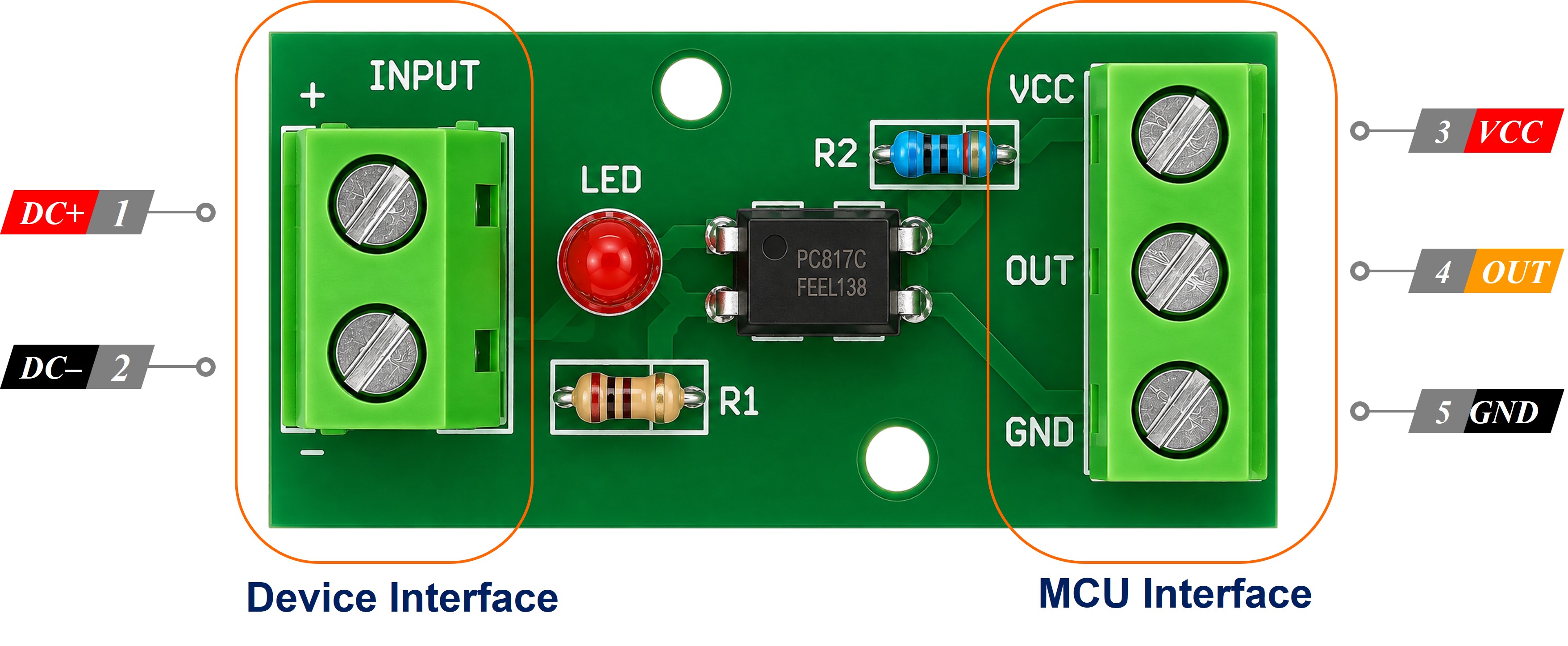
- Pin 1 — Anode (A): + of the isolated signal, arriving through the series resistor
- Pin 2 — Cathode (K): ground of the 12V/24V circuit, not the Arduino UNO Q GND
- Pin 3 — Emitter (E): Arduino UNO Q GND
- Pin 4 — Collector (C): Arduino UNO Q digital input pin
Size the resistor for roughly 10 mA of LED current:
$$R = \frac{V_{in} - 1.2}{0.01}$$
- 3.3V → 220 ohm (about 9.5 mA)
- 5V → 390 ohm (about 9.7 mA)
- 12V → 1 kohm (about 10.8 mA)
- 24V → 2.2 kohm (about 10.4 mA, use a 1/2 W part)
Move the same circuit from a 12V line to a 24V line and that resistor has to change with it — precisely the mistake the three module variants exist to take off your hands.
The Isolation Rule
The ground of the 12V/24V circuit must not be joined to the Arduino UNO Q GND. Keeping the two grounds apart is the whole point — it is that separation, not the chip itself, that protects the board. Tie them together and the PC817 still switches happily, but the isolation is gone and you are back to a direct wire between the machine and your Linux processor.
Wiring Diagram
The Arduino UNO Q's STM32 MCU is a 3.3V part, so the output side of the optocoupler is pulled up to 3.3V and never higher. Whether the isolated side is running at 12V or at 24V makes no difference to the pin — the transistor either shorts it to GND or leaves it alone.
Wiring the PC817 Optocoupler Module
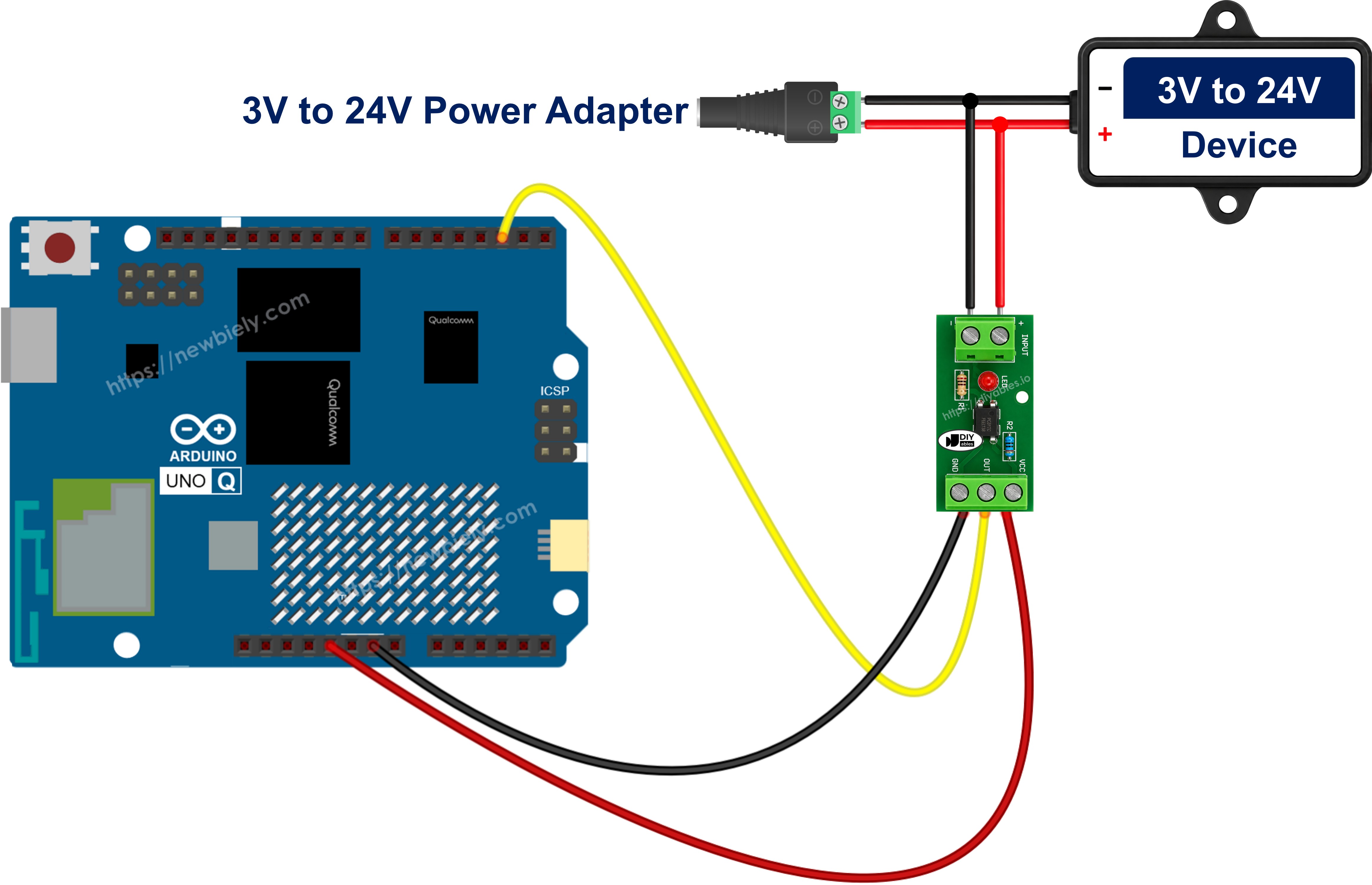
This image is created using Fritzing. Click to enlarge image
Five terminals, and the split between them is the isolation barrier itself — IN+ and IN- belong to the machine, VCC/GND/OUT belong to the Arduino UNO Q, and no wire crosses between the two groups.
| Module terminal | Connect to |
|---|---|
| IN+ (input side) | + of the 12V/24V signal |
| IN- (input side) | ground of the 12V/24V circuit (keep it separate from the board GND) |
| VCC (output side) | Arduino UNO Q 3.3V |
| GND (output side) | Arduino UNO Q GND |
| OUT / DO (output side) | Arduino UNO Q pin 2 |
※ NOTE THAT:
Feed the module's VCC from the 3.3V pin, not from 5V. The module's output pin follows whatever you put on VCC, and the STM32 input on the Arduino UNO Q expects 3.3V. And remember that the module you fit must be the variant matching that 12V or 24V signal — a mismatch is not something the code can correct.
Wiring the Bare PC817 Chip
| PC817 pin | Connect to |
|---|---|
| Pin 1 - Anode (A) | series resistor, then the + of the 12V/24V signal (1 kohm for 12V, 2.2 kohm for 24V) |
| Pin 2 - Cathode (K) | ground of the 12V/24V circuit (keep it separate from the board GND) |
| Pin 3 - Emitter (E) | Arduino UNO Q GND |
| Pin 4 - Collector (C) | Arduino UNO Q pin 2, using INPUT_PULLUP |
The internal pull-up is the easiest option and it ties the pin to the MCU's own 3.3V rail. If you would rather use an external one, fit a 10 kohm resistor from pin 2 to the 3.3V pin of the Arduino UNO Q — not to 5V, which the STM32 inputs are not made for.
Wiring the PC817 in Parallel Across the Load
Both diagrams above quietly assume the 12V/24V line is yours to wire from scratch. On a real machine it is not: the line already feeds something, and that something is precisely what you came to watch. The optocoupler therefore goes across the existing device — in parallel with it, hanging off the same two terminals the device is already sitting on.
Take the run/fault lamp line of a 24V industrial machine, the same line the Telegram section further down turns into "Conveyor 3 started". The lamp is wired between the cabinet's switched 24V and its 0V return, and a 24V module simply joins it there:
| Tap from | Goes to |
|---|---|
| Switched + terminal of the 24V lamp | module IN+ |
| 0V return terminal of the 24V lamp | module IN- |
There is no resistor to add on the tap: the 24V module already carries the right one, which is the entire reason for buying the variant that matches the line. (On the bare-chip route this is where the 2.2 kohm goes, in series with pin 1.)
Nothing in the cabinet is cut, unplugged or rerouted. The tap draws a few milliamps, which is nothing beside what a lamp, a contactor coil, a solenoid valve or a motor is already pulling, so the machine carries on behaving exactly as it did — a read-only measurement bolted alongside the circuit rather than inserted into it.
※ NOTE THAT:
Never put the optocoupler in series with the device. Wired in line, the full load current of that lamp, coil or motor is forced through the internal LED, and the PC817 is destroyed the instant the circuit switches on — the on-board resistor of a module does nothing to save it. Its input side is an LED rated in tens of milliamps and nothing more. Across the device, always.
Four details decide whether the tap works the first time:
- Polarity is not optional. IN+ and IN- are the two ends of an LED, so current passes one way only. Reverse them and the optocoupler never lights — no damage, no reading, and no hint as to why. Confirm which of the two terminals is the positive one before stripping a wire.
- Clamp an inductive load with a diode. A contactor coil, relay, solenoid valve or motor throws a large reverse spike the moment it drops out, and the PC817 input LED withstands only 6 V in reverse. Fit an ordinary diode reverse-parallel straight across the module's input terminals — diode cathode on IN+, diode anode on IN- (pins 1 and 2 on the bare chip). In normal operation it is reverse-biased and does nothing at all; on a spike it conducts and holds the reverse voltage well under a volt. A 1N4148 handles small taps, a 1N4007 the heavier ones.
- Add a bleeder resistor if the reading never clears. PLC transistor outputs, triac outputs and LED-lamp drivers commonly leak a milliamp or so while switched off. That trickle is enough to partly light the input LED, and the Arduino UNO Q then reports the machine as running while the cabinet sits dark — the giveaway is a reading that never falls back to ABSENT, and the module's status LED glowing faintly. A 4.7 kohm to 10 kohm resistor fitted across the input terminals gives the leakage an easier path than the LED, and the reading settles.
- DC lines only. With a single LED on its input the PC817 answers to one polarity, so it is the wrong part for sensing an AC line — that calls for an optocoupler whose input stage carries two back-to-back LEDs.
Monitoring Whether the Machine Is On or Off
Sitting across the device instead of ahead of it, the pin follows the machine's real electrical state rather than your intentions for it. An operator leaning on the physical start button, a PLC energising the line on a schedule, a timer elsewhere in the cabinet closing a contact — the Arduino UNO Q sees every one of them. Just as valuably, it sees the case where a start is commanded and the line stays dead. That is what lifts the circuit from a signal detector to a run-hour counter, an idle-time log, a fault-lamp watchdog and a "did it actually start?" check.
That last one is where the Linux half of the Arduino UNO Q pays for itself: the Bridge section below hands each transition to Python, and the Telegram section after it turns the transition into a message within a second — so a start command that produces no 24V becomes an alert on your phone instead of a discovery made hours later.
※ NOTE THAT:
One honest limitation: the PC817 tells you the device is energised, not that it is doing its job. A seized motor, a burnt-out heater element or a jammed conveyor still draws power from the line and still reads as PRESENT. To know that the machine is genuinely working, watch current, temperature or motion alongside this signal.
How To Program For PC817
- Choose the pin the module's OUT terminal goes to:
- Declare the polarity of your module in one place, so a wrong guess is a one-line fix rather than a hunt through the sketch:
- Enable the internal pull-up so the pin sits at 3.3V while the isolated line is dead:
- Read the raw pin level, then resolve it through the constant instead of hard-coding LOW anywhere:
- Act on the result:
- To catch the moment the line switches rather than its level, remember the previous reading and compare:
No library is needed for any of this — a PC817 is read with plain digitalRead(), exactly like a button or a limit switch, only with 24 volts kept safely on the other side of the gap.
Arduino UNO Q Code
The Arduino UNO Q has two processors working together:
- The STM32 MCU owns the isolated input pin and reads it every 500 ms
- The Qualcomm MPU runs Debian Linux with Wi-Fi — it stays idle in this first section, and a later section brings it into play through Bridge
Detailed Instructions
First time with Arduino UNO Q? Follow the Getting Started with Arduino UNO Q tutorial before proceeding.
- Pick the right module variant first: the 24V module for a 24V line, the 12V module for a 12V line, the 3-5V module for logic-level signals. This is the one choice the code cannot rescue.
- Wire the module: Follow the wiring diagram above, and double-check that the 12V/24V ground is nowhere near the Arduino UNO Q GND.
- Connect: Plug the Arduino UNO Q into your computer with the USB-C cable.
- Open Arduino App Lab: Launch Arduino App Lab and wait until it detects your Arduino UNO Q.
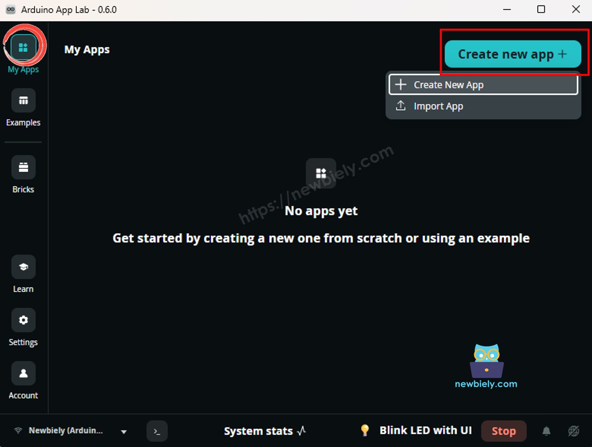
- Create a new App: Click the Create New App button.
- Give the App a name, for example: PC817IsolatedInput
- Click Create to confirm.
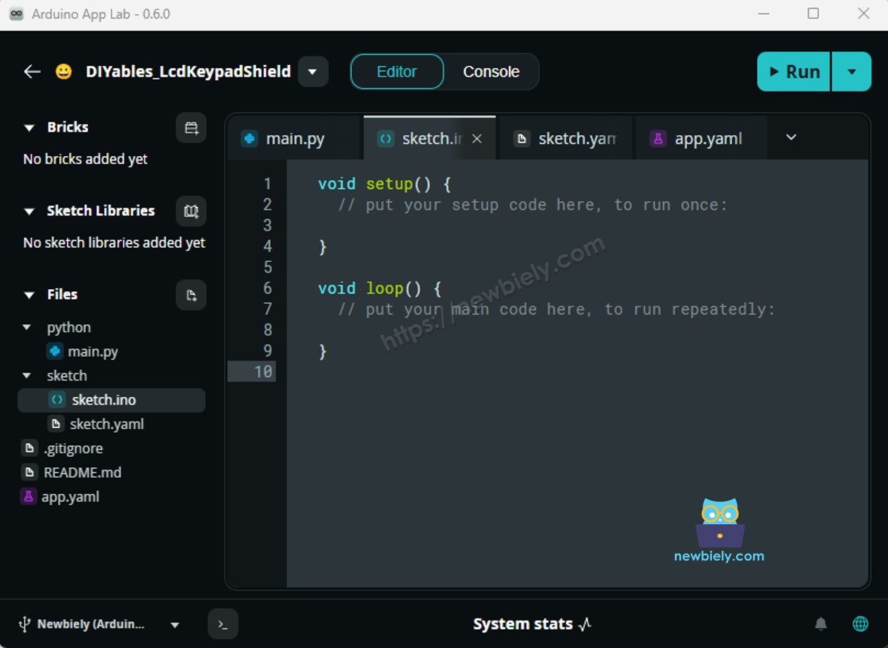
- Paste the sketch: Copy the MCU code above into sketch/sketch.ino. Keep the other files as default.
- No library required — the PC817 is read with the built-in digitalRead() function.
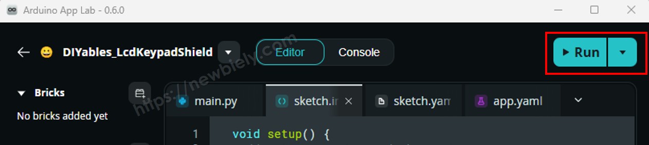
- Upload: Click the Run button in Arduino App Lab.
- Switch the isolated 12V/24V signal on and off while watching the Serial Monitor — this doubles as the polarity test described earlier.
App Lab Console Output
※ NOTE THAT:
Seeing PRESENT when the machine is off, and ABSENT when it is on? Your module inverts on-board — set MODULE_ACTIVE_LOW to false and run it again, and leave the wiring alone. If instead the pin never changes at all, the usual cause is a variant mismatch: a 24V module fed from a 12V line barely lights its LED. Check the module's status LED against the console before touching anything else.
Bridge: Linux + MCU
This section wires both processors of the Arduino UNO Q together so the Linux side can see the isolated input:
- The PC817 output is on an MCU pin — the MCU watches it in loop(), debounces it, resolves it through MODULE_ACTIVE_LOW, and remembers each change as an event
- The MPU cannot touch that pin — it asks over RPC with Bridge.call("get_line") for the state and Bridge.call("get_event") for a pending change. It receives a finished "present" / "absent", never a raw pin level, so module polarity is settled once on the MCU and never again. The MCU only ever answers; nothing on the Linux side can drive the isolated input
- The MPU has Wi-Fi — full Debian Linux, so it can log every transition to a file or fire a Telegram message within a second of the machine starting
- Arduino_RouterBridge provides the RPC link between the two processors
- ⚠️ /dev/ttyHS1 (Linux) and Serial1 (MCU) are RESERVED by the router — never open them in user code
In short: 24V line changes → MCU records the event → MPU polls it over Bridge → Linux logs it or sends it on. If you want the full picture of how the two processors talk, see Communication Between Linux and MCU.
MCU Code (Bridge)
Python Code (Bridge)
Detailed Instructions
- Connect: Keep the same wiring — the optocoupler stays on the MCU side.
- Open Arduino App Lab and create a new App named PC817Bridge.
- Paste the MCU sketch into sketch/sketch.ino.
- Paste the Python code into the App's Python file.
- If you had to set MODULE_ACTIVE_LOW to false in the first sketch, set it the same way here — it is the only line that has to agree between the two.
- Install the library: Click the Add sketch library button (the open book icon with a + sign) in the left sidebar.
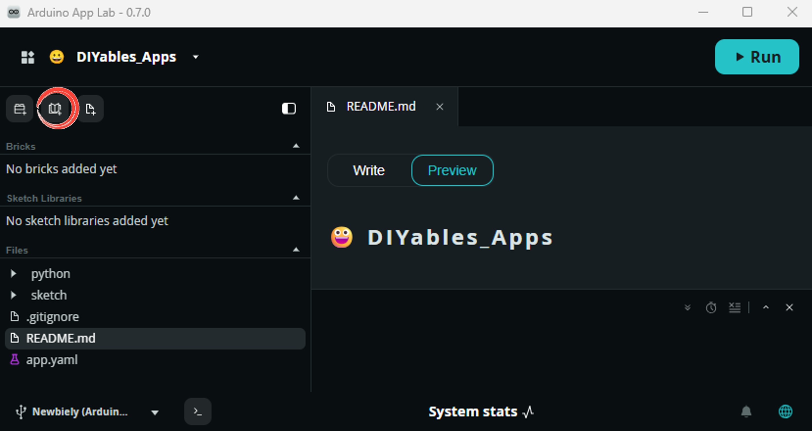
- Search for Arduino_RouterBridge created by Arduino and click the Install button.
- Upload: Click the Run button.
- Toggle the isolated 12V/24V signal and watch both consoles react.
- ⚠️ Warning: Do not open /dev/ttyHS1 on Linux or use Serial1 on the MCU — the Arduino Router owns them, and touching them breaks the Bridge.
App Lab Console Output
Telegram
A 12V or 24V line does not have a value to compare against — it is either there or it is not. So the useful alert here is a state-change alert: the bot messages you the moment the isolated line goes live and again when it goes dead, which on a machine cabinet reads as "started" and "stopped".
If you do not have a bot yet, see How to Create a Telegram Bot first.
MCU sketch: Keep the same MCU sketch from the previous Bridge section.
Python Code (Telegram)
Detailed Instructions
- Replace YOUR_TELEGRAM_BOT_TOKEN with your bot token from BotFather.
- Replace YOUR_CHAT_ID with your Telegram chat ID.
- Change MACHINE_NAME to whatever the 24V line actually belongs to.
- Paste this Python code into your App's Python file, keeping the same MCU sketch.
- Nothing in this file knows or cares about module polarity — the MCU has already resolved it, so there is no second setting to keep in step.
- Click the Run button, then switch the isolated line on and off — an alert should land in Telegram within a second.
- Send /line at any time to ask whether the 24V signal is present right now.
App Lab Console Output


ArduinoBot
OpenClaw
You can adapt the OpenClaw to this tutorial by refering the instruction on Arduino Uno Q - OpenClaw Tutorial
Project Ideas
The isolated input becomes a lot more interesting once the Linux side gets involved:
- 24V machine uptime logger: Take the 24V "running" lamp line of a machine into a 24V module — Python timestamps every start and stop into a CSV on the Linux filesystem and sends a Telegram summary each evening with total runtime and cycle count
- Run-hour counter and idle-time log: Treat the isolated input purely as an on/off monitor for one device — Python keeps a running total of how many hours the machine has been energised, how long it sat idle between jobs, and how many times it started, then answers a /hours Telegram command with the day's figures
- Fault lamp watchdog: Put a second 24V module on the fault lamp circuit and expose it as its own Bridge function — Linux alerts you the instant the fault line lights, and stays quiet as long as it is dark
- 12V pump dashboard: Monitor a 12V pump's coil supply with a 12V module and serve the live state from the Linux side as a small web page, so anyone on the network can see whether the pump is running
- Vehicle ignition tracker: Watch a 12V ignition or headlight circuit — the Linux side records how long the circuit stayed live per trip and pushes the total to Telegram when it goes dead
- PLC output mirror: Read a 24V PLC output with the optocoupler and mirror it onto a relay driven by another MCU pin, letting the UNO Q act as a safe bridge between an industrial cabinet and your own low-voltage gear
Challenge Yourself
Ready to push the PC817 further on Arduino UNO Q? Try these:
- Easy: Light the on-board LED whenever the isolated line is present, and change the printed labels from PRESENT/ABSENT to wording that fits your own machine.
- Medium: Add a get_on_count Bridge function that counts how many times the 24V line has gone live since boot, plus a get_on_seconds function returning how long it has been live this cycle — then report both with a /stats Telegram command.
- Advanced: Wire a 4-channel 24V module to four MCU pins, expose all four states in a single Bridge call, and have Python send one Telegram message naming exactly which channel changed — the beginning of a small isolated I/O monitor for a whole cabinet.