
Raspberry Pi - 10 Segment LED Bar Graph
This tutorial instructs you how to use Raspberry Pi to control the 10 Segment LED Bar Graph display. In detail, we will learn:
- How to connect Raspberry Pi to the 10 Segment LED Bar Graph
- How to program Raspberry Pi using Python to animate the LED bar display
...SUGGEST
LINK_SUGGEST_RASPBERRY_PI_LED
LINK_SUGGEST_RASPBERRY_PI_BUTTON_LED
...SUGGEST
Overview of 10 Segment LED Bar Graph
| 10 Segment LED Bar Graph | |
|---|---|
| Number of Segments | 10 |
| LED Color | Bright red |
| Forward Voltage | ~2V per segment |
| Forward Current | 20mA max per segment |
| Resistor Required | 220Ω per segment |
The LED Bar Graph Pinout
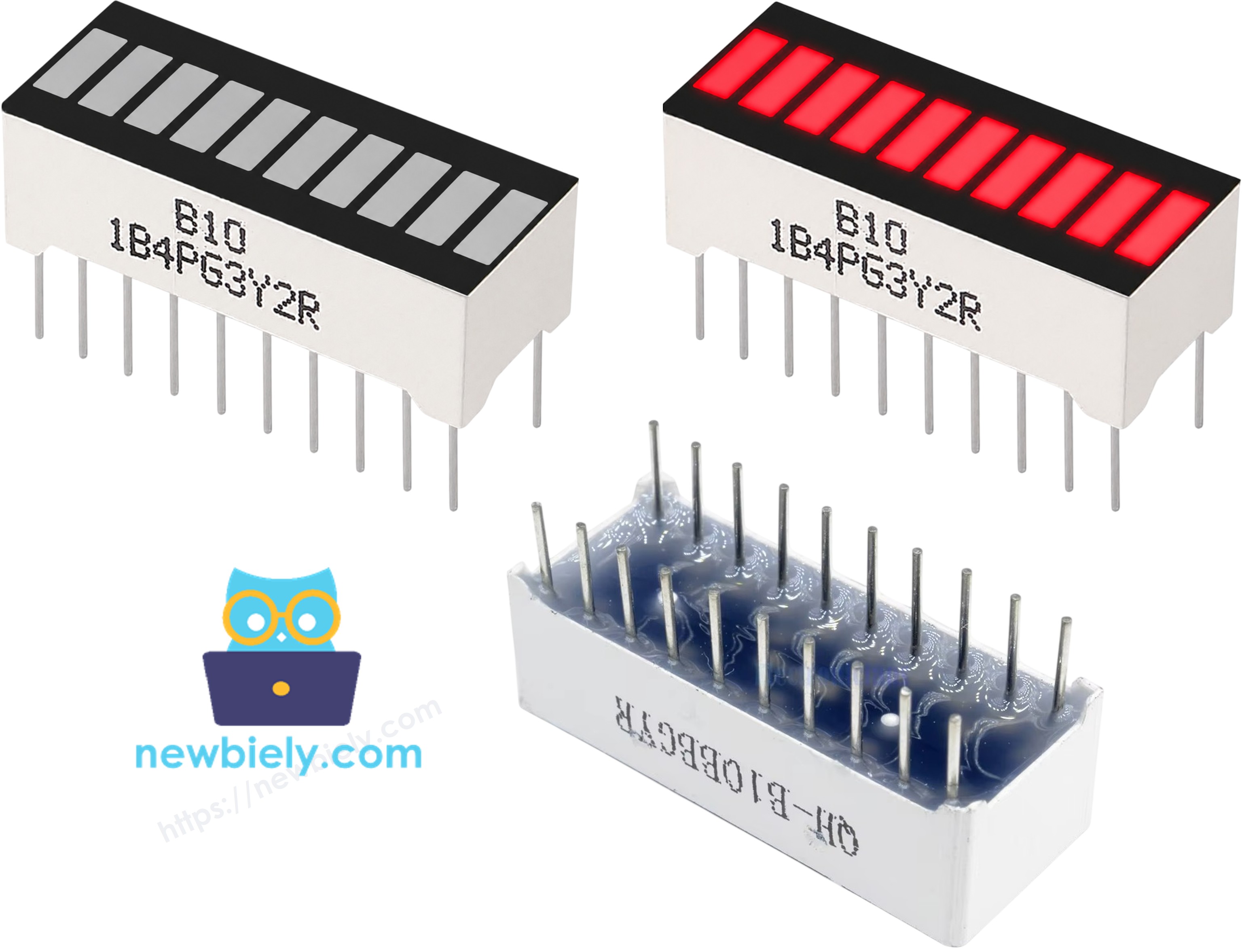
The 10 Segment LED Bar Graph has 20 pins:
- Anode pins (A1–A10): This set of pins must be connected to Raspberry Pi GPIO pins via 220Ω resistors
- Cathode pins (K1–K10): This set of pins must be connected to ground (0V)
※ NOTE THAT:
The arrangement of pins on your LED bar graph can differ between manufacturers. Always verify the anode and cathode orientation using the component datasheet before wiring. Be sure to take a close look!
Wiring Diagram
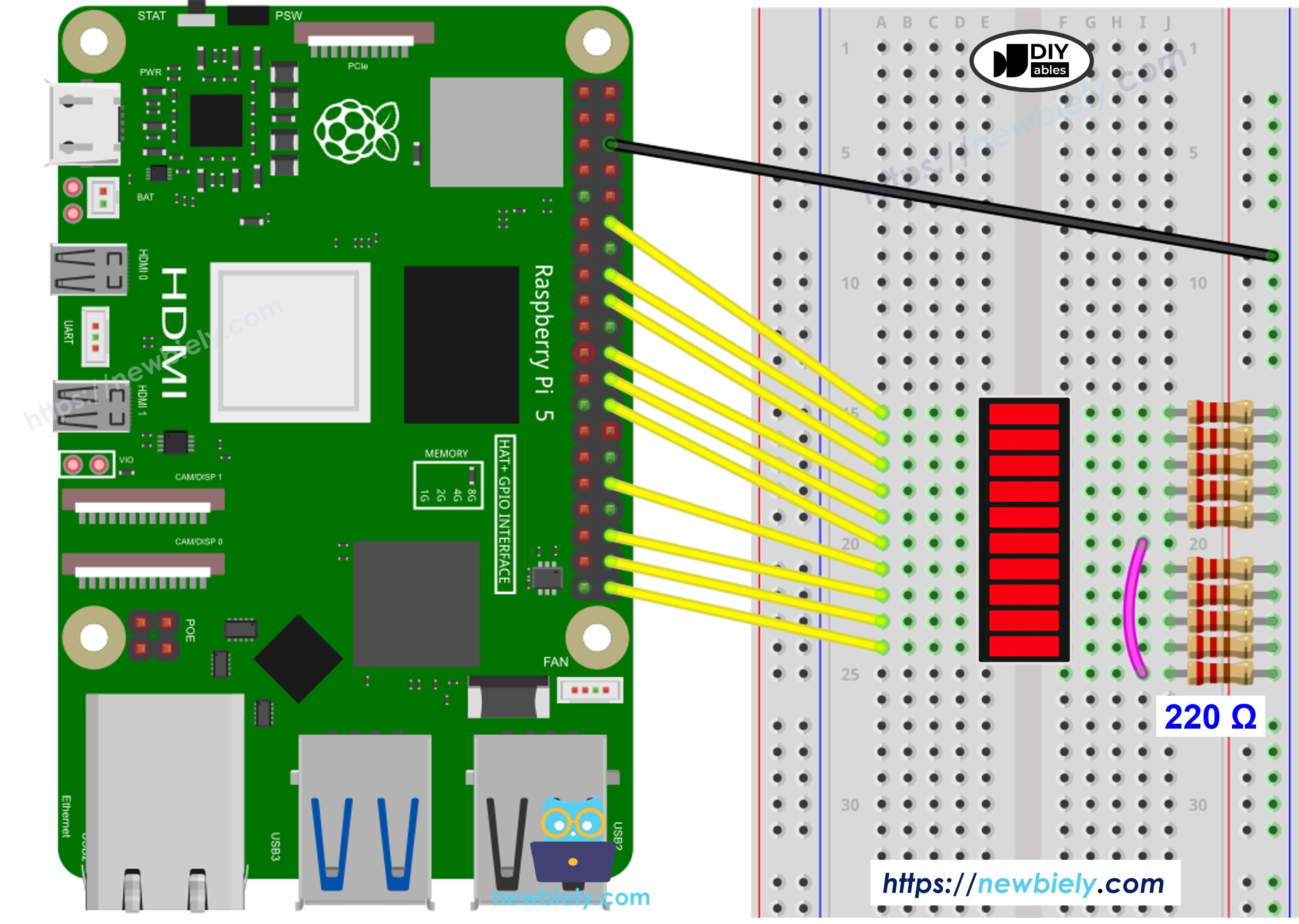
This image is created using Fritzing. Click to enlarge image
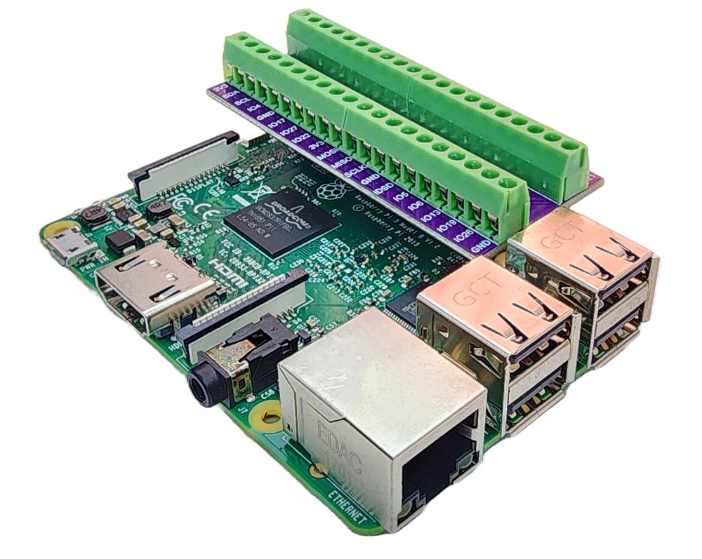
To simplify and organize your wiring setup, we recommend using a Screw Terminal Block Shield for Raspberry Pi. This shield ensures more secure and manageable connections, as shown below:
- LED Bar Graph A1 to Raspberry Pi GPIO 18 (pin 12) via 220Ω resistor
- LED Bar Graph A2 to Raspberry Pi GPIO 23 (pin 16) via 220Ω resistor
- LED Bar Graph A3 to Raspberry Pi GPIO 24 (pin 18) via 220Ω resistor
- LED Bar Graph A4 to Raspberry Pi GPIO 25 (pin 22) via 220Ω resistor
- LED Bar Graph A5 to Raspberry Pi GPIO 8 (pin 24) via 220Ω resistor
- LED Bar Graph A6 to Raspberry Pi GPIO 7 (pin 26) via 220Ω resistor
- LED Bar Graph A7 to Raspberry Pi GPIO 12 (pin 32) via 220Ω resistor
- LED Bar Graph A8 to Raspberry Pi GPIO 16 (pin 36) via 220Ω resistor
- LED Bar Graph A9 to Raspberry Pi GPIO 20 (pin 38) via 220Ω resistor
- LED Bar Graph A10 to Raspberry Pi GPIO 21 (pin 40) via 220Ω resistor
- All K1–K10 (Cathodes) to Raspberry Pi GND (any GND pin)
※ NOTE THAT:
All 10 anode pins are wired down a single row of the 40-pin header (the even-numbered pins: 12, 16, 18, 22, 24, 26, 32, 36, 38, 40), keeping the wiring straightforward. This uses GPIO8 and GPIO7, which double as the SPI CE0/CE1 chip-select lines — safe here since this project doesn't use SPI. GPIO1 (the other HAT ID EEPROM pin) and the UART pins (GPIO14/GPIO15) are avoided entirely.
Or you can buy the following kits:
| 1 | × | DIYables Sensor Kit (18 sensors/displays) |
Additionally, some of these links are for products from our own brand, DIYables .
How To Program Raspberry Pi to Control LED Bar Graph
The script below drives all 10 segments in sequence — lighting them one by one from A1 to A10, then extinguishing them in reverse, while printing the live bar state to the terminal.
Detailed Instructions
- Make sure you have Raspbian or any other Raspberry Pi compatible operating system installed on your Pi.
- Make sure your Raspberry Pi is connected to the same local network as your PC.
- Make sure your Raspberry Pi is connected to the internet if you need to install some libraries.
- See LINK_TUTORIAL_RASPBERRY_PI_GETTING_STARTED if you haven't set up your Raspberry Pi yet.
- Connect your PC to the Raspberry Pi via SSH using an SSH client such as PuTTY.
- Make sure the RPi.GPIO library is installed. If it is not already present on your system, install it by running:
- Wire the components according to the wiring diagram above.
- Create a Python script file LedBarGraph.py and add the following code:
- Run the script with the following command:
- Check the results on the terminal — you will see the bar animation printed as text.
Raspberry Pi Console Output
The script continuously animates the LED bar, printing the state every 100ms. Stop the script at any time by pressing Ctrl + C in the terminal — the KeyboardInterrupt handler will automatically clean up the GPIO state.
Additional Knowledge
Each GPIO pin on the Raspberry Pi can safely source or sink a maximum of 16mA, with a combined limit of approximately 50mA across all GPIO pins simultaneously. Always use a 220Ω resistor in series with each LED segment to keep the current within safe bounds and protect both the Pi and the LED bar graph from damage.
The 10 Segment LED Bar Graph is well suited for a range of practical applications on the Raspberry Pi: displaying battery or power levels, visualising audio signal strength, showing the progress of a long-running automation script, or acting as a simple status indicator in home-automation and IoT projects running directly on the Pi.