
Raspberry Pi - MAX6675 Thermocouple Module
A regular digital temperature sensor will not survive being dropped into a kiln, a soldering iron tip, or the exhaust of a running engine. For jobs like that, makers reach for a thermocouple instead, paired with a small converter chip called the MAX6675. This tutorial walks through wiring one up to a Raspberry Pi and reading it from Python. In detail, we will learn:
- What a thermocouple is and why it can survive extreme temperatures.
- How the MAX6675 module turns the thermocouple's tiny voltage into a temperature reading.
- How to wire the module to the Raspberry Pi's GPIO header.
- How to talk to the MAX6675 from Python, since there is no ready-made library for it here, we will bit-bang its 3-wire interface ourselves.
Hardware Preparation
Or you can buy the following kits:
| 1 | × | DIYables Sensor Kit (18 sensors/displays) |
Additionally, some of these links are for products from our own brand, DIYables .
What Is A Thermocouple?
A thermocouple is simply two wires made of different metals, joined together at one end. That joint, called the hot junction, generates a tiny voltage that rises and falls with temperature. Because it is just two bits of wire and nothing else that can melt or burn out, a thermocouple can be poked into places a normal sensor would never survive. The most common variety is the Type-K probe (Chromel and Alumel wires), rated from roughly -328°F up to +2300°F.
Overview of The MAX6675 Thermocouple Module
The tiny voltage a thermocouple produces is far too small and noisy for a microcontroller to read directly, that is the job of the MAX6675. The module pairs the MAX6675 chip with a screw terminal for the probe: a small breakout board carrying the chip, a handful of support components, and a 2-pin terminal block, plus a roughly 18-inch Type-K probe wired to it (red lead to the "+" terminal, blue lead to the "-" terminal). The probe itself is only rated for 0-80°C even though the module can digitize readings across a much wider range, so keep that limit in mind when picking where to stick it.
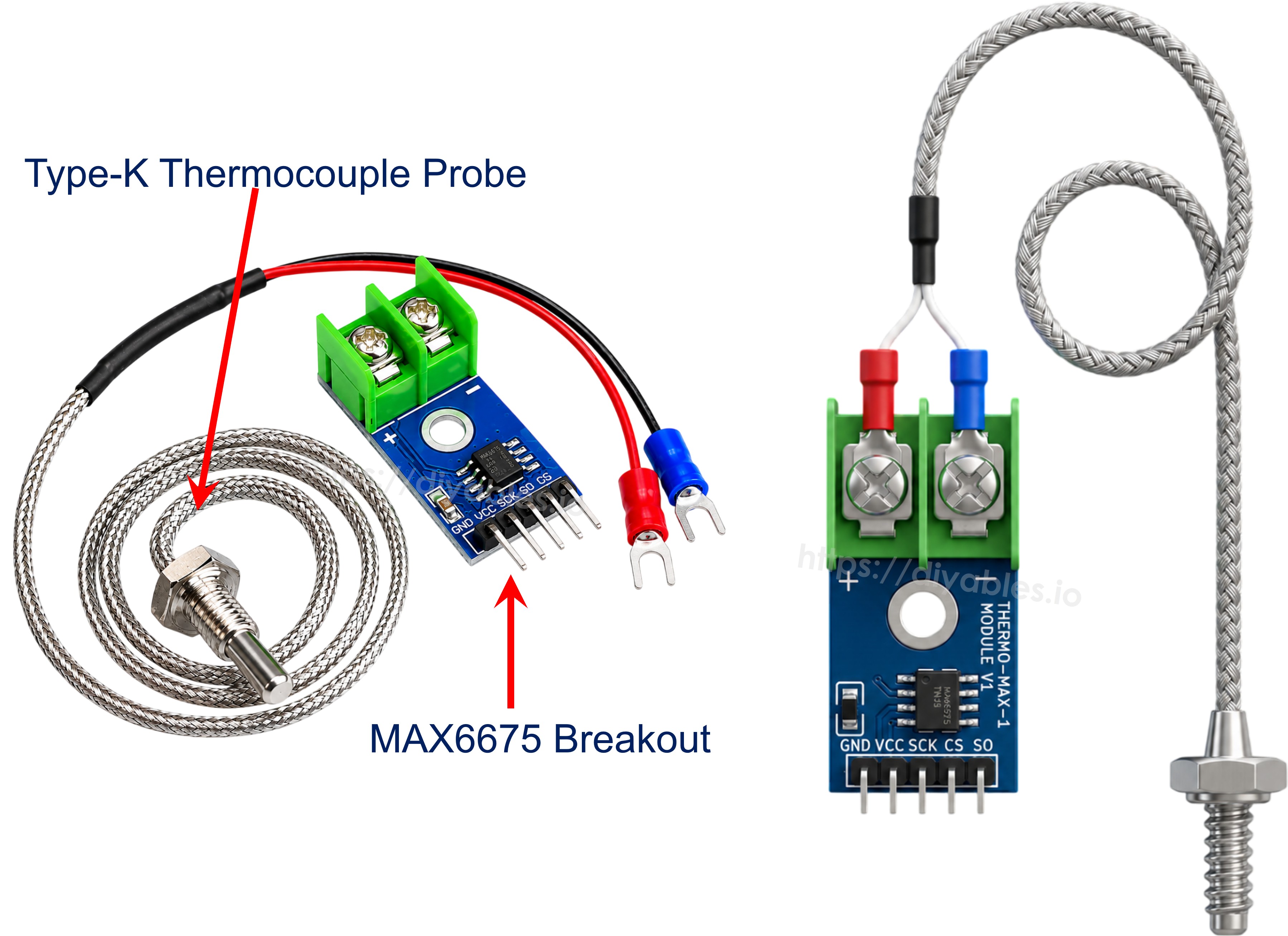
Key specs:
- Operating voltage: 3.0V to 5.5V
- Measurable range: 0°C to 1024°C (the bundled probe itself is only rated to 80°C)
- Accuracy: ±3°C
- Resolution: about 0.25°C
The module breaks out 5 pins:
- VCC pin: power input, 3.0V to 5.5V.
- GND pin: ground.
- SCK pin: serial clock, driven by the Raspberry Pi.
- CS pin: chip select, pulled LOW to tell the module to send a reading.
- SO pin: serial data out, this is the only data line on the chip, there is no data-in pin since the MAX6675 has nothing to be configured.
Wiring Diagram
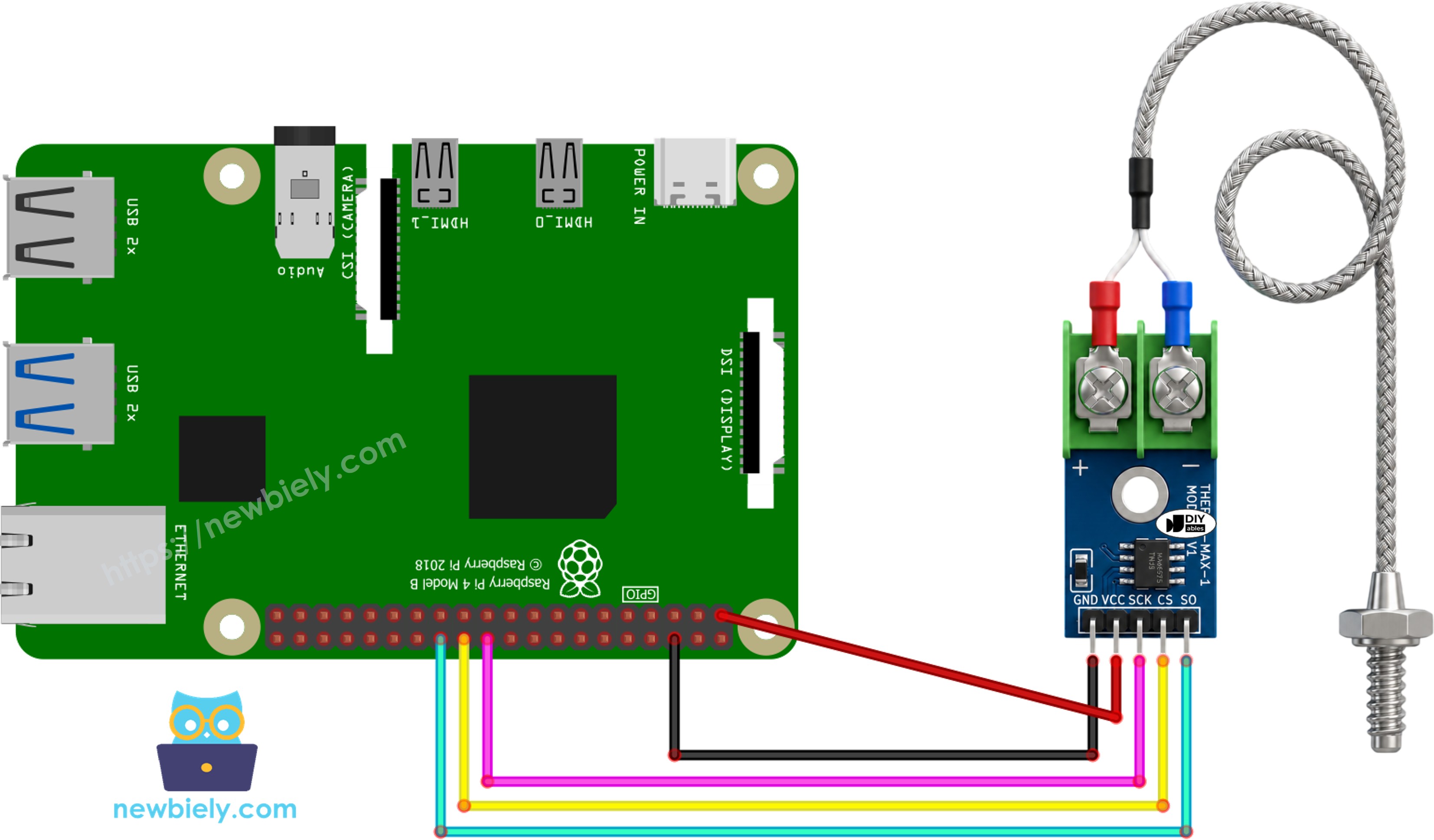
This image is created using Fritzing. Click to enlarge image
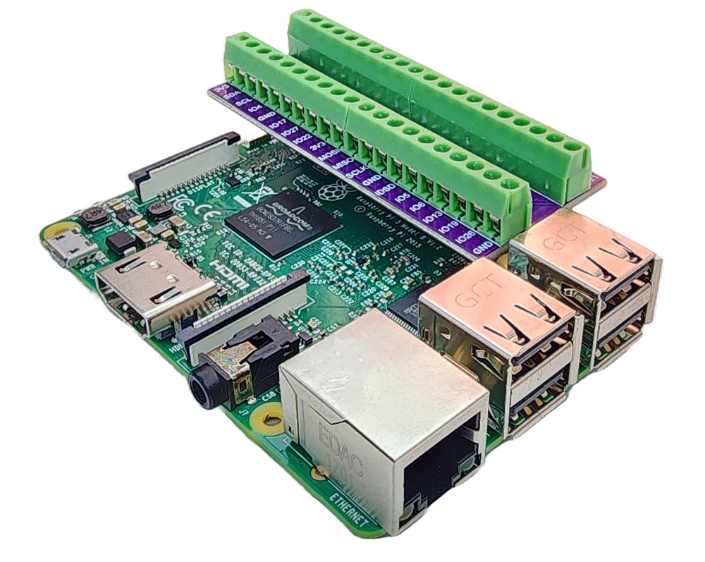
To simplify and organize your wiring setup, we recommend using a Screw Terminal Block Shield for Raspberry Pi. This shield ensures more secure and manageable connections, as shown below:
| MAX6675 Pin | Raspberry Pi Pin |
|---|---|
| VCC | 3.3V (Pin 1) |
| GND | GND (Pin 6) |
| SCK | GPIO25 (Pin 22) |
| CS | GPIO8 (Pin 24) |
| SO | GPIO7 (Pin 26) |
※ NOTE THAT:
Wire VCC to the Raspberry Pi's 3.3V pin, not the 5V pin. Raspberry Pi GPIOs cannot tolerate 5V, and the MAX6675 is happy running on 3.3V, so there is no reason to risk it.
Raspberry Pi Code
Detailed Instructions
- Make sure you have Raspbian or any other Raspberry Pi compatible operating system installed on your Pi.
- Make sure your Raspberry Pi is connected to the same local network as your PC.
- Make sure your Raspberry Pi is connected to the internet if you need to install some libraries.
- If this is the first time you use Raspberry Pi, See how to set up the Raspberry Pi
- Connect your PC to the Raspberry Pi via SSH using the built-in SSH client on Linux and macOS or PuTTY on Windows. See to how connect your PC to Raspberry Pi via SSH.
- Make sure you have the RPi.GPIO library installed. If not, install it using the following command:
There is no separate driver library to install for the MAX6675 itself, since the chip's interface is simple enough to drive straight from RPi.GPIO, no SPI overlay or third-party package required.
- Create a Python script file max6675_thermocouple.py and add the following code:
- Save the file and run the Python script by executing the following command in the terminal:
- Leave the probe tip sitting in open air for a few seconds, then dip it into a mug of hot water.
- Watch the readings climb in the terminal.
- Unplug the probe from the terminal block and run the script again, you should see the fault message instead of a reading:
The script runs in an infinite loop continuously until you press Ctrl + C in the terminal.
Code Explanation
The MAX6675 has no library to call here because its whole interface is just a clocked shift register, so the script talks to it directly through GPIO:
- SCK_PIN, CS_PIN, and SO_PIN are set up with GPIO.setup(), the first two as outputs since the Raspberry Pi drives them, and SO_PIN as an input since that is the only pin the module talks back on.
- read_celsius() pulls CS_PIN LOW to wake the module up, then toggles SCK_PIN 16 times. On each pulse it reads SO_PIN and shifts that bit into raw_value, most significant bit first, which is how the MAX6675 streams out its 16-bit word.
- Once all 16 bits are in, CS_PIN goes back HIGH to release the module.
- Bit D2 of that word (checked with raw_value & 0x4) is a fault flag, if it is set the probe is not connected and the function returns None instead of a bogus reading.
- Otherwise, bits D14 down to D3 hold the actual 12-bit count, shifting raw_value right by 3 and multiplying by 0.25 converts it to degrees Celsius, which is then also converted to Fahrenheit for display.